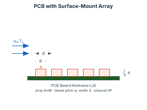
PCB Component Array — Forced Convection
Calculates the mean case temperature of surface-mounted components on a PCB cooled by a forced-air flow channel. The model accounts for:
- Convection coefficient from Will's empirical correlation.
- Local air temperature rise due to upstream component heating.
- Component exposed surface area (top and side faces).
- PCB fin efficiency distributing heat laterally and streamwise through the board copper.
- Interface resistance via the standoff air gap and leads in parallel.
Will's Correlation
h=G⋅um0.8where G = 6.2 (no card guides) or G = 7.6 (card guides at PCB leading edges). Valid for air at near-ambient conditions, u_m = 0.2 – 8 m/s.
Local Air Temperature
Heat dissipated by all components upstream of row N raises the local air temperature:
Tl=Ta+um⋅Nb⋅a⋅ρ⋅Cpq⋅M⋅(N−1)where a=Wb⋅HF−M⋅S⋅e is the free-flow area.
Thermal Resistance
The component-to-air resistance combines convection from the exposed top/side faces (A1) and a conduction path through the PCB (A2, corrected for fin efficiency) in parallel with the interface resistance:
A1=S⋅b+2e(S+b) R=hA1+Ri+hA2111PCB Fin Efficiencies
M1=2w−SC12h,E1=M1tanhM1 C1=tb(kb+kcϕ1),C2=tb(kb+kcϕ2)where ϕ1, ϕ2 are the fraction of the board cross-section that is copper (dimensionless, e.g. 0.05 = 5 % copper). The copper equivalent thickness ϕtb converts the volume fraction to the length scale required by the conductance.
Interface Resistance
The air-gap conduction and lead conduction act in parallel:
rc=kaSbδ,rl=klnleadsAlLlead Ri=1/rc+1/rl1Component Temperature
Tc=Tl+q⋅RReferences
- Thermal Analysis of Air-Cooled PCBs, Electronic Production, Parts 1–4, May–August 1983.
- Rajaram, S., Thermal Design of Electronic Equipment for Reliability & Performance, AT&T Bell Laboratories, Session 3, pp. 20–42.