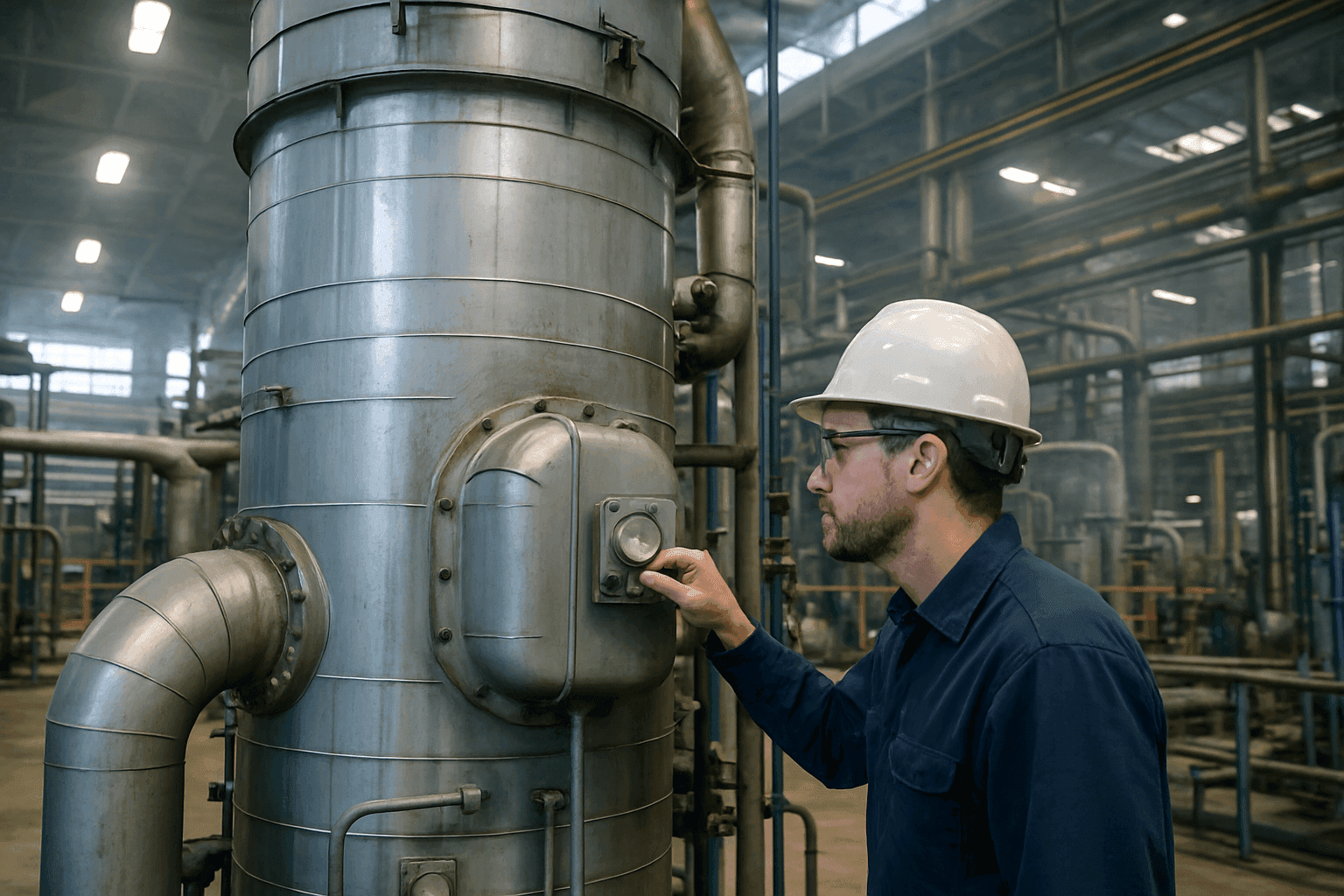
Optimizing Performance: The Industrial Thermal Oxidizer Maintenance Schedule
Industrial thermal oxidisers are critical air pollution control systems, indispensable for manufacturing facilities and industrial processes that generate Volatile Organic Compounds (VOCs), Hazardous Air Pollutants (HAPs), and odorous emissions. These systems effectively destroy airborne pollutants by subjecting them to extremely high temperatures, converting hydrocarbon molecules into less harmful compounds—primarily carbon dioxide (CO2) and water vapour (H2O). Given their pivotal role in environmental compliance, worker safety, and overall operational efficiency, implementing a rigorous preventative maintenance schedule for industrial thermal oxidisers is not merely an operational best practice; it is a strict regulatory necessity.
Consistent thermal oxidiser upkeep ensures optimal destruction removal efficiency (DRE)—typically targeted at 98% to 99.9%—prevents costly unplanned production downtime, minimises fuel consumption, extends equipment lifespan, and guarantees ongoing adherence to environmental permits (such as Title V permits in the US or Medium Combustion Plant Directive (MCPD) regulations in the UK and Europe). Neglecting thermal oxidiser maintenance can lead to decreased destruction efficiency, increased auxiliary fuel usage, catastrophic equipment failures, severe environmental fines, and complete plant shutdowns.
Types of Industrial Thermal Oxidisers and Their Maintenance Considerations
While the core principle of thermal oxidation—using heat to break chemical bonds—remains consistent, different oxidiser designs require distinct operational parameters and maintenance considerations. Understanding these structural differences is crucial for developing an effective emissions control equipment servicing plan.
Regenerative Thermal Oxidisers (RTOs)
RTOs are highly favoured for their exceptional thermal efficiency, often exceeding 95%. This is achieved using structured or random ceramic media beds (heat sinks) that absorb heat from the clean exhaust gas and transfer it to the incoming untreated process stream. This regenerative heat transfer significantly reduces the requirement for auxiliary burner fuel, making them highly economical for high-volume streams with low VOC concentrations.
- Maintenance Focus: Key RTO maintenance areas include the ceramic heat exchange media, switching valves (poppet valves), chamber insulation, and process air fans. Regular inspection of the ceramic media for particulate fouling, chemical masking (e.g., from silicones or inorganic dusts), structural cracking, or thermal shock damage is vital. System operators must closely monitor the pressure drop (ΔP) across the media beds. A rising pressure drop indicates plugging, which limits process flow and strains the main draft fan. Additionally, the poppet valves must seat perfectly and switch rapidly; any mechanical lag or seal wear will bypass untreated VOCs directly to the stack, violating emission limits.
Catalytic Oxidisers (COs)
Catalytic oxidisers route the VOC-laden stream through a precious metal catalyst bed (typically platinum, palladium, or rhodium deposited on a ceramic monolith or metallic substrate). The catalyst lowers the required activation energy of the oxidation reaction, allowing VOC destruction to occur at much lower temperatures—typically between 260°C and 480°C, compared to the 760°C to 870°C required by thermal units. This translates to substantial fuel savings.
- Maintenance Focus: The primary maintenance priority is preserving catalyst activity. Catalysts can suffer from "masking" (reversible coating by dust, soot, or heavy organic compounds) or "poisoning" (irreversible chemical bonding with sulfur, phosphorus, heavy metals, or silicone compounds). Regular catalyst activity testing (core sampling), physical cleaning (low-pressure air lancing), and occasional thermal "burn-out" cycles are essential. Additionally, monitoring the temperature rise across the catalyst bed (ΔT) is critical, as it directly reflects the volume of VOCs being oxidised.
Direct Fired Thermal Oxidisers (DFTOs) and Recuperative Thermal Oxidisers
Direct Fired Thermal Oxidisers (DFTOs)—often referred to as afterburners—direct the process air directly into a high-temperature combustion chamber with no preheating. Recuperative thermal oxidisers improve on this basic design by incorporating a primary gas-to-gas heat exchanger (shell-and-tube or plate-frame) to preheat the incoming process stream using the thermal energy of the clean exhaust air.
- Maintenance Focus: For DFTOs and recuperative units, the burner assembly, combustion chamber refractory, and heat exchanger require meticulous inspection. Heat exchangers are susceptible to thermal expansion stresses, leading to weld cracks or tube failures. A cracked heat exchanger allows untreated process gas to leak directly into the clean exhaust stream, causing instant compliance failure. The thermal recovery efficiency (ηth) of recuperative systems should be monitored using the following calculation:
Where:
- ηth is the thermal recovery efficiency of the preheater.
- Tpreheat is the temperature of the preheated process air entering the burner zone (°C).
- Tinlet is the raw process air temperature at the system inlet (°C).
- Tcombustion is the operating temperature within the combustion chamber (°C).
A drop in ηth indicates fouling or internal leakage within the heat exchanger core, requiring immediate cleaning or seal repair.
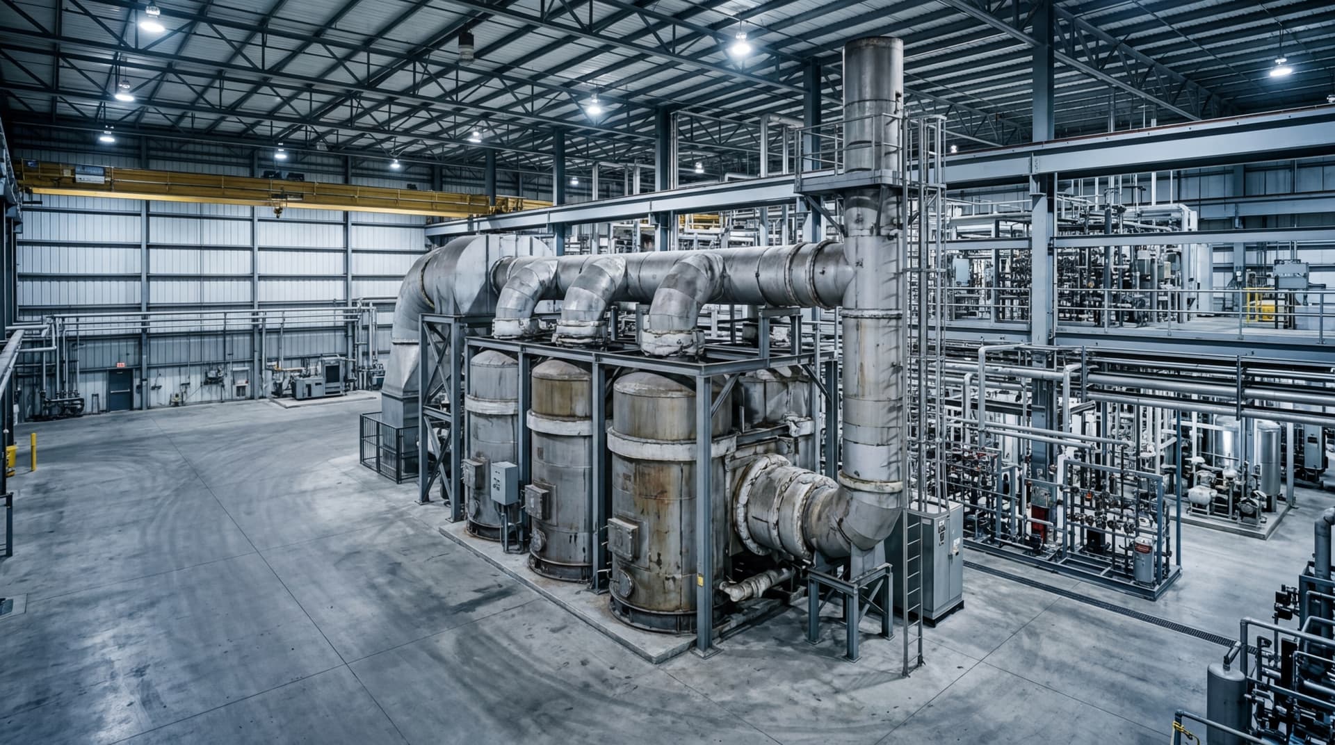
Achieve >99% VOC destruction efficiency with thermal oxidiser systems designed for chemical, pharmaceutical, food, and coatings applications.
Key Components Requiring Regular Maintenance
Regardless of system configuration, specific mechanical, thermal, and electrical components must be systematically inspected to ensure reliable, continuous operation:
- Combustion Chamber/Oxidation Chamber: The main refractory-lined chamber where destructive oxidation occurs. Refractory insulation must be checked for cracking, spalling, structural sagging, and anchoring failures.
- Burner System: Includes the fuel gas train, pilot assembly, flame scanner (UV or IR detector), spark igniter, and burner tile. Flame stability, fuel-to-air ratios, and nozzle cleanliness must be maintained to prevent soot formation and fuel waste.
- Heat Exchangers and Ceramic Media Beds: Critical for energy conservation. Inspected for physical obstruction, particulate buildup, chemical scaling, or thermal stress cracking.
- Fans and Blowers: The system's motive force. Draft fans must be monitored for impeller wear, particulate deposition (which causes rotor imbalance and severe vibration), bearing lubrication, and drive belt tension.
- Valves and Dampers: Includes flow control dampers, bypass valves, and RTO switching valves. Must be checked for pneumatic cylinder wear, solenoid valve functionality, limit switch calibration, and seat gasket degradation.
- Insulation and Refractory lining: Keeps the intense heat (up to 1,000°C) contained. Outer casing "hot spots" exceeding 65°C above ambient temperature point to localized internal refractory failure.
- Control System and Instrumentation: Programmable Logic Controllers (PLCs), continuous emission monitors (CEMS), and safety-critical sensors. Dual or triple-redundant thermocouples must be calibrated regularly to prevent inaccurate temperature readings and thermal runaway.
- Ducting and Exhaust Stack: Subject to corrosion from acidic condensation (e.g., from chlorinated or fluorinated VOCs). Must be checked for structural integrity, weld leaks, and expansion joint fatigue.
- Inlet Filters: Capture larger particulates before they enter the heat recovery beds or catalyst. Require routine pressure drop monitoring and replacement.
General Principles of Thermal Oxidiser Preventative Maintenance
A proactive preventative maintenance (PM) strategy reduces overall operational costs by identifying sub-component degradation before it results in a catastrophic failure or environmental breach.
- Rigorous Scheduled Inspections: Create a calendar-based PM schedule detailing daily, weekly, monthly, quarterly, and annual checks.
- Comprehensive Data Logging: Keep meticulous records of critical parameters: temperatures, pressure drops, valve cycle times, fan vibration levels, and fuel consumption. Modern PLCs should trend this data to facilitate predictive analysis.
- Predictive Maintenance Technologies: Utilise specialised diagnostics such as thermal imaging (thermography) of the oxidiser shell, oil analysis on fan gearboxes, and vibration signature analysis on major motors.
- Strategic Spare Parts Inventory: Minimise lead-time delays by stocking high-failure-risk and long-lead components onsite (e.g., replacement thermocouples, flame scanners, limit switches, pneumatic solenoids, valve seat gaskets, and burner spark plugs).
- Comprehensive Operator Training: Ensure plant operators understand the relationship between process changes (e.g., sudden VOC surges) and oxidiser reaction behaviours to prevent thermal shocks or safety shutdowns.
- Professional Service Partnerships: Partner with qualified thermal oxidiser specialists for comprehensive annual mechanical and structural audits, safety system validation (NFPA 86 or EN 746-2 compliance), and stack testing.
Detailed Industrial Thermal Oxidiser Maintenance Schedule
The following schedule serves as a detailed baseline checklist. Maintenance frequencies should be adjusted based on the continuousness of your operation, exhaust stream particulate load, and corrosive chemical concentration.
Daily Maintenance
- Log Operating Temperatures: Verify the combustion chamber temperature is maintained within the permitted compliance range (typically 760°C to 870°C for RTOs).
- Monitor Differential Pressure (ΔP): Log the pressure drop across the inlet filter, catalyst bed, or ceramic media beds. Compare against clean baseline values.
- Visual Inspection: Walk the perimeter to check for visible exhaust plume opacity, unusual system noise, or major mechanical vibrations.
- Safety and Interlocks: Check that the flame scanner signal is active and stable. Confirm all access doors are fully sealed. Verify that continuous recording instrumentation is online and logging data without error codes.
Weekly Maintenance
- Examine Burner Flame Profile: Inspect the burner flame through the viewport. It should be stable, well-anchored to the burner nozzle, and display a clean blue colour (for natural gas), indicating complete combustion.
- Pneumatic and Air Lines: Check compressed air pressure regulator settings. Ensure compressed air dryers are functioning to prevent moisture condensation in control lines and valve actuators.
- Exterior Casing Scan: Conduct a visual walk-around to identify any discoloured paint, warping, or heat distortion on the outer steel skin—early indicators of localized internal refractory insulation failure.
- Inlet Filters: Check filter differential pressure gauges. Clean or replace pre-filters if they are approaching the manufacturer's maximum ΔP limit.
- Hardware and Linkages: Tighten any loose structural bolts or damper linkages that may have loosened due to fan-induced vibration.
Monthly Maintenance
- Fan and Motor Lubrication: Grease process fan and combustion blower bearings according to the manufacturer’s specification. Use high-temperature, high-speed grease as recommended.
- Examine Fan Drive Belts: Inspect fan drive belts (if applicable) for correct tension, alignment, and physical wear (cracking or fraying).
- Purge System Lines: Open drain valves on air pressure switch sensing lines to purge accumulated moisture or organic condensates that could distort sensor readings.
- Bypass Damper Verification: Perform a physical stroke test of the emergency bypass damper to guarantee rapid, unhindered operation in the event of an emergency shutdown.
- RTO Switching Valve Inspection: For RTO units, check the pneumatic cylinder stroke and ensure the switching valves are transitioning cleanly without sticking or physical bottoming-out. Check for wear on shaft packings.
Quarterly Maintenance
- Control System Calibration: Calibrate temperature controllers and verify thermocouple accuracy. Even a minor thermocouple drift of 15°C can lead to massive fuel wastage or an regulatory compliance violation.
- Clean Spark Igniters and Flame Scanners: Remove the spark plug and flame scanner. Clean carbon deposits or soot from the probes and clean the optical sight lens.
- Test Safety Interlocks: Verify safety PLC trip reactions by simulating fault conditions (e.g., high-temperature limits, low airflow, fuel gas pressure high/low, and loss of flame signal).
- Inspect Damper Seals: Inspect internal damper blade seals for warping, tearing, or particulate buildup that could prevent tight shut-off.
Semi-Annual Maintenance
- Internal Oxidiser Inspection: Perform a confined-space entry (following all local health and safety regulations) to inspect the interior chamber. Check ceramic media for structural settling, verify refractory wall anchors are secure, and check for bypass pathways around media beds.
- Fan Impeller Inspection: Inspect process fan blades for corrosion, erosion, or particulate accumulation. Clean and balance the impeller if vibration levels are climbing.
- Thermographic Survey: Conduct a professional infrared thermal imaging scan of the entire external casing while operating at normal processing temperatures to map out refractory thinning or insulation voids.
Annual Maintenance
- Full Burner Tune-up: Adjust fuel gas/air ratios across the burner operating range using a combustion analyser to optimise thermal efficiency and minimise Carbon Monoxide (CO) and Nitrogen Oxide (NOx) emissions.
- Catalyst Activity Testing (COs): Take a core sample of the catalyst media and submit it to an approved laboratory for activity testing. This determines the remaining life of the catalyst and the temperature required to maintain compliant VOC destruction.
- Thermal Media Deep Clean: For systems running dirty streams, execute an organic "bake-out" cycle. This involves raising the inlet/outlet media temperature to approximately 350°C to 400°C under controlled, low-VOC conditions to safely vaporise and oxidise accumulated organic condensates. If inorganic fouling is present, arrange for a physical water wash-down or chemical clean.
- Recuperative Heat Exchanger Integrity Test: Run a dye-penetrant or pressure decay test on recuperative heat exchangers to verify there are no micro-fractures allowing cross-contamination between raw process air and treated exhaust.
- Compliance Stack Testing: Co-ordinate with environmental agencies to run formal stack emissions testing to renew your operating licence and formally document VOC destruction efficiency.
As Needed / Predictive Maintenance
- Sensor Replacement: Replace thermocouples every 1 to 2 years, or immediately upon detecting a calibration drift.
- Refractory Patching: Repair minor refractory cracks or replace missing ceramic fibre modules during scheduled down-periods to prevent structural damage to the outer steel shell.
- Catalyst Rejuvenation or Replacement: If lab analysis reports catalyst poisoning or severe masking that cannot be cleaned onsite, schedule chemical rejuvenation or complete catalyst replacement.
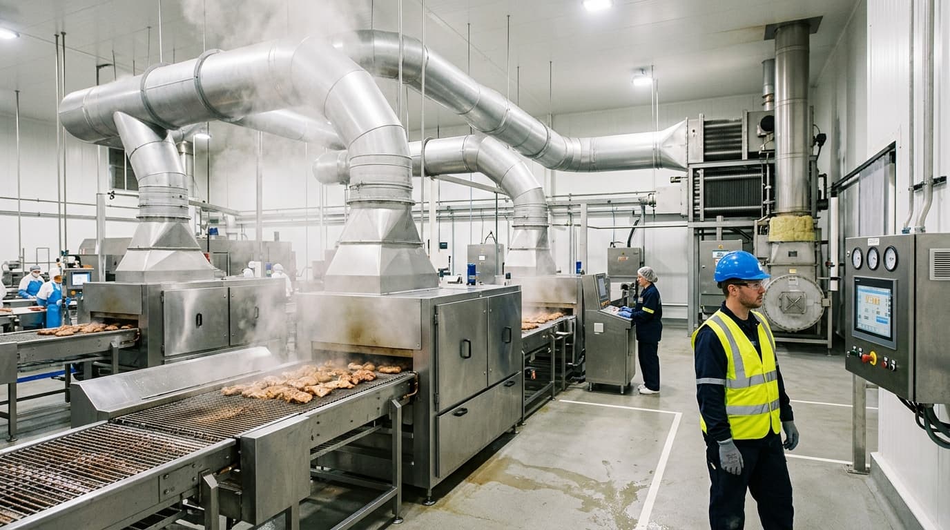
Regenerative and recuperative thermal oxidisers that convert harmful process emissions into clean exhaust while recovering up to 95% of thermal energy.
RTO Troubleshooting Logic Flow
To assist maintenance technicians in diagnosing the most common RTO performance drop, follow this structured troubleshooting logic flow:
Troubleshooting Common Thermal Oxidiser Problems
When operating parameters stray outside normal tolerances, fast, accurate diagnostics are required to prevent safety trips and production shutdowns. Use the following guide to troubleshoot common performance failures:
| Symptom | Potential Cause | Diagnostic & Corrective Action |
|---|---|---|
| Insufficient destruction efficiency (DRE) | Operating temperature too low; gas bypass through leaking valves/dampers; cracked recuperative heat exchanger core; catalyst poisoning. | Verify thermocouple calibration; inspect and replace switching valve gaskets; perform a leak check on the heat exchanger; send catalyst sample for activity analysis. |
| High pressure drop across media/catalyst | Particulate accumulation; organic condensation; ceramic media crumbling or melting due to local thermal runaway. | Run a high-temperature thermal bake-out; execute a low-pressure air lance or water wash; inspect media internally and replace damaged sections. |
| Flame instability or frequent flame failure trips | Dirty flame scanner lens; incorrect fuel-to-air ratio; fluctuating inlet process gas flow; worn spark igniter. | Clean the UV/IR scanner lens; recalibrate the gas control valve; tune the burner; replace the spark plug igniter. |
| Unusual casing hot spots (> 100°C) | Localised failure of refractory lining or ceramic fibre insulation modules. | Perform thermographic scanning; during next shutdown, enter the chamber to pack voids with ceramic fibre and apply refractory patching compound. |
| Excessive fuel consumption | Fouled heat exchanger; leaking bypass damper; low inlet VOC concentration; incorrect burner tuning. | Clean heat recovery surfaces; test bypass damper sealing; adjust air/fuel ratio; optimise process upstream to concentrate VOC loads. |
Benefits of a Robust Industrial Thermal Oxidiser Maintenance Programme
Investing in a comprehensive, preventative maintenance programme for your industrial thermal oxidiser yields substantial financial and operational returns:
- Guaranteed Regulatory Compliance: Avoids catastrophic environmental permit violations, severe fines, and forced legal shutdowns by ensuring your system consistently meets emission limits.
- Maximised Fuel and Energy Efficiency: Keeping heat exchangers clean and burners properly tuned minimises auxiliary fuel consumption, substantially reducing utility costs.
- Dramatically Reduced Unplanned Downtime: Identifying and resolving component wear during planned maintenance shutdowns prevents sudden in-production failures that stall manufacturing operations.
- Extended Capital Asset Lifespan: Well-maintained thermal oxidisers can operate reliably for 20 to 30 years. Neglected units can suffer structural, corrosive, or thermal failures requiring complete replacement in under 10 years.
- Enhanced Facility Safety: Regular inspections of fuel safety trains, burner interlocks, and flame detection systems significantly reduce the risk of industrial explosions, fires, and dangerous workplace emissions.
By strictly adhering to a structured maintenance schedule and combining in-house daily/weekly checks with annual professional engineering audits, manufacturing facilities can ensure their thermal oxidisers operate at peak efficiency, satisfy all environmental standards, and support sustainable, cost-effective plant operations.
