[Radiation]
Free tool

Aligned Parallel Plates

Net radiant heat exchange between two equal, directly-opposed gray plates.

[FREE_TOOLS]
Built by our engineers
[EXPLORE]
More tools, always free
[CALCULATOR]
Inputs
Results
View factor F₁₂
——
Net heat rate
—W
Net flux (per A₁)
—W/m²
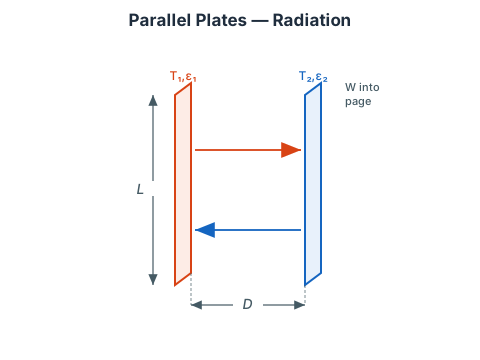
Aligned Parallel Plates — schematic
[READ_THE_NUMBERS]

Results are indicative

Figures assume typical conditions and the stated method. For measured, guaranteed numbers on your plant, our engineers run site surveys, heat loss audits, and full process models.

[NEXT_STEP]

Send us the result — we'll tell you what it means for your plant.

[ABOUT_THIS_TOOL]

Aligned Parallel Plates

Computes the net radiant heat exchange between two equal, isothermal gray rectangles (L×W) mounted face-to-face and directly opposed, separated by a gap D.

View Factor

With the dimensionless ratios

x=DL​,y=DW​

the shape factor for two aligned parallel rectangles is

F12​=πxy2​[ln1+x2+y2(1+x2)(1+y2)​​+x1+y2​tan−11+y2​x​+y1+x2​tan−11+x2​y​−xtan−1x−ytan−1y]

As the plates become large compared with the gap (x,y→∞) the view factor approaches unity; for square plates with x=y=1 it gives F12​≈0.200.

Net Radiant Exchange

For a two-surface gray, diffuse enclosure,

Q=ε1​A1​1−ε1​​+A1​F12​1​+ε2​A2​1−ε2​​σ(T14​−T24​)​

with σ=5.670374×10⁻⁸ W/m2K4, A1​=A2​=LW, and temperatures in Kelvin. When both surfaces are black this reduces to Q=σA1​F12​(T14​−T24​).

References

[UPGRADE]

Need this tool, but deeper?

We build advanced versions on request — your fluids, your geometry, your standards, validated against plant data.

[REQUEST]

Missing a calculator?

Tell us what you're sizing or estimating — we build the calculators engineers actually ask for.

[FAQ]

Frequently asked questions

Net radiant heat exchange between two equal, directly-opposed gray plates. Enter your inputs and press Calculate — the worked solution shows every step of the method with your numbers substituted in.

A gray surface has an emissivity that is constant across wavelength, so one number ε between 0 and 1 characterises how it emits and absorbs. It is the standard engineering idealisation; real oxidised metals and painted surfaces follow it closely enough for plant calculations.

Use the built-in table as a starting point: polished aluminium is around 0.05, oxidised steel around 0.8, painted or anodised surfaces around 0.9. Surface condition dominates — use the in-service condition, not the as-machined one.