All calculators
[Head-Loss]
Free tool

Wire-Screen Head Loss

Pressure drop across a wire-mesh screen in a duct (Re > 10³).

[FREE_TOOLS]
Built by our engineers
[EXPLORE]
More tools, always free
[FIELD_NOTE]

Every K = 1 component costs one velocity head — about 60 Pa at 10 m/s in air — and fan power rises with the cube of the flow you push through it.

[LIVE_TOOL]Results update as you type
[READ_THE_NUMBERS]

Results are indicative

Figures assume typical conditions and the stated method. For measured, guaranteed numbers on your plant, our engineers run site surveys, heat loss audits, and full process models.

[NEXT_STEP]

Send us the result — we'll tell you what it means for your plant.

[ABOUT_THIS_TOOL]

Wire-Screen Head Loss

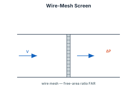
Calculates the pressure-drop loss coefficient and pressure drop across a circular metallic wire-mesh screen fitted inside a pipe or duct.

Free Area Ratio

FAR=Total AreaFree Area

The free area ratio must be entered directly. For a standard woven wire mesh, FAR is determined from the wire diameter and mesh pitch.

Loss Coefficient

For Reynolds numbers Re > 10³ (turbulent regime):

K=1.3(1FAR)+(FAR1FAR)2

The first term represents viscous drag on the wires; the second is the contraction-expansion inertial loss through the mesh openings.

Pressure Drop

Δp=K21ρV2

where ρ is the air density at the specified temperature and V is the mean flow velocity in the duct upstream of the screen.

Validity

  • Pipe (duct) Reynolds number Re > 10³.
  • Circular metallic wire mesh inside a circular or rectangular duct.
  • FAR must be in the range (0, 1).

References

  • Idel'chik, I.E. and Fried, E., Flow Resistance, a Design Guide for Engineers, Taylor & Francis, Washington D.C., 1989, p. 265.
[UPGRADE]

Need this tool, but deeper?

We build advanced versions on request — your fluids, your geometry, your standards, validated against plant data.

[REQUEST]

Missing a calculator?

Tell us what you're sizing or estimating — we build the calculators engineers actually ask for.

[FAQ]

Frequently asked questions

Pressure drop across a wire-mesh screen in a duct (Re > 10³). Enter your inputs and press Calculate — the worked solution shows every step of the method with your numbers substituted in.

K expresses a component's pressure drop in velocity heads: Δp = K·½ρV². A K of 1 means the component destroys exactly the kinetic energy of the approaching flow. It is dimensionless, so the same K applies at any flow rate — the pressure drop then scales with velocity squared.

Compute each component's Δp at its local velocity and add them, together with straight-duct friction. Where the duct area is constant you can equivalently sum the K values first. The result is the static pressure the fan must develop at that flow rate.