Improving Manifold Airflow Evenness by 65% for Industrial Incinerators
A waste incineration equipment manufacturer faced rising production costs associated with the air distribution manifold on its industrial incineration unit. The original tubular design, while technically effective, had become economically unsustainable, leading the client to explore a simplified box-section design. Initial assessments indicated that the proposed geometric changes would disrupt the uniform airflow required for efficient combustion on the incineration grate, potentially compromising ash formation management. A thermal engineering consultancy was commissioned to analyse the proposed manifold and optimise the flow distribution to ensure performance parity with the original equipment.
The Engineering Challenge
The primary technical constraint was the mass flow consistency across the incineration grate. Consistent airflow is critical for maintaining stable combustion conditions and preventing localised hotspots or cold zones. The proposed box-section design introduced significant challenges in air distribution, as the beam geometry altered the pressure drop and flow paths compared to the established tubular model.
The team needed to ensure the mass flow for each nozzle was as uniform as possible. The goal was to minimise the variability across the nozzle bank, ensuring that the incineration process remained predictable and efficient. This required a rigorous approach to process modelling to evaluate how the new structural components influenced fluid dynamics.
The Modelling Approach
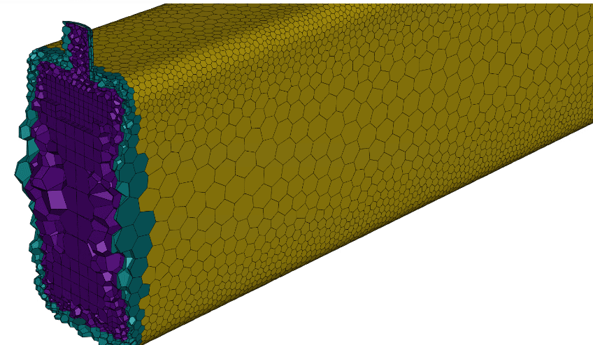
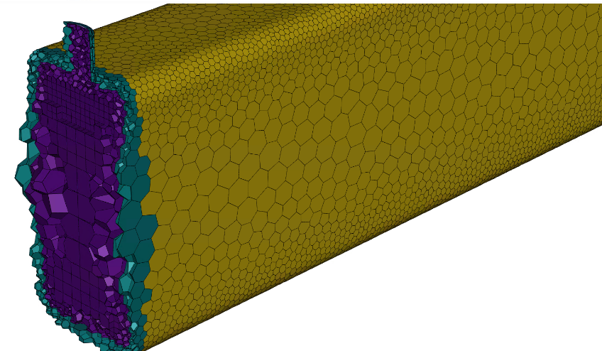
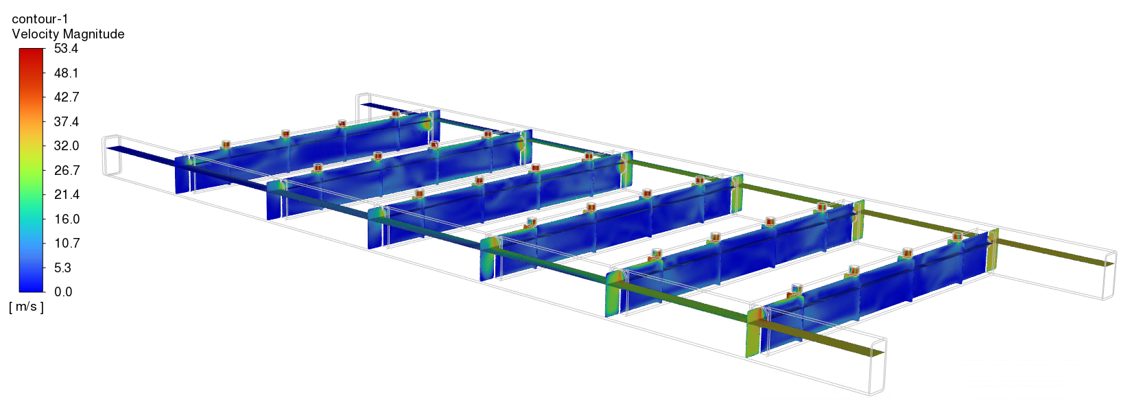
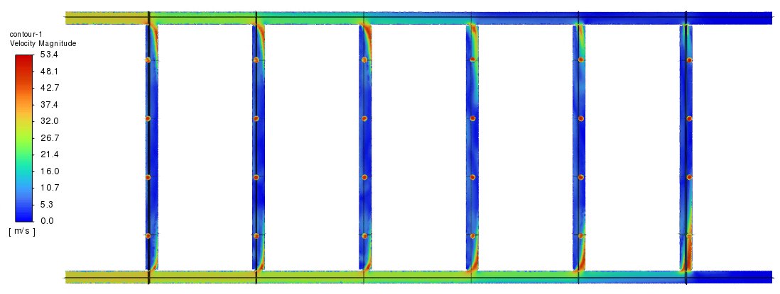
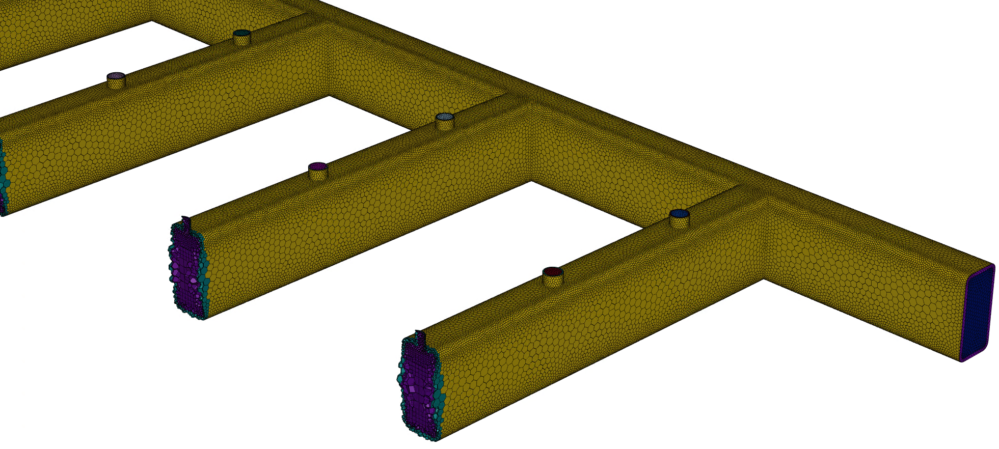
The team utilised CFD to replicate the operational environment of the industrial incineration unit. The simulation utilised a baseline mass flow of 1,750 m³/h at 20°C. The modelling software created a precise digital twin of the proposed manifold geometry, including all nozzles and cross members, to evaluate pressure and velocity profiles.
The Coefficient of Variation (COV) was selected as the key metric to quantify flow uniformity, providing a benchmark against which all design iterations could be measured.
By capturing the intricacies of each nozzle, the simulation ensured that the pressure and flow dynamics would converge to provide accurate data. This enabled the lead project engineer to identify exactly where flow resistance was occurring and where distribution was uneven.
Iterative Optimisation
The optimisation process relied on an iterative methodology. By systematically adjusting the diameters of the inlet infeed holes and modifying the internal beam geometry, the project lead ran a series of trials to balance pressure and mass flow. Throughout the project, 14 distinct design iterations were modelled, analysed, and refined.
Each iteration was subjected to the same rigorous flow criteria to determine if it achieved the required combustion uniformity. The method involved a combination of trial-and-error adjustment and fundamental principles of fluid dynamics.
Analysis of Findings
While velocity distribution was monitored, the team prioritised mass flow uniformity as the primary performance indicator for combustion efficiency. The data indicated that the differential pressure increased slightly from 1,597 Pa in the original design to 1,697 Pa in the final iteration. This was a critical insight for the client, as it provided the necessary data to specify the correct fan and blower capacity to maintain the required flow rates during operation.
| Metric | Original Design | Optimised Design (DC14) |
|---|---|---|
| Mass Flow Improvement | Baseline | 65% increase in evenness |
| Differential Pressure | 1,597 Pa | 1,697 Pa |
| Expected Nozzle Velocity | - | 53 m/s |
The Optimised Solution
Among the various trials, the final iteration - designated as DC14 - demonstrated the lowest COV and root mean square error (RMSE), confirming it as the optimal solution for manufacturing. This design achieved a 65% improvement in flow evenness compared to the initial box-section model. With an expected nozzle velocity of 53 m/s at full flow, this solution enables uniform combustion across the grate, ensuring that ash formation can be managed effectively.
By validating the new manifold design through detailed process optimisation, the manufacturer successfully transitioned to a more cost-effective fabrication method. This project demonstrates that structural redesign for cost reduction does not necessitate a trade-off in operational performance, provided that detailed engineering simulation is employed to guide the design process.

Managing Director — EnerTherm Engineering
Dr. François Pierrel is Managing Director of EnerTherm Engineering with over two decades of expertise in thermal design, heat transfer, and industrial energy optimisation. He holds a PhD in Heat Transfer from Cranfield University and a Post-Doctorate from Heriot-Watt University.
