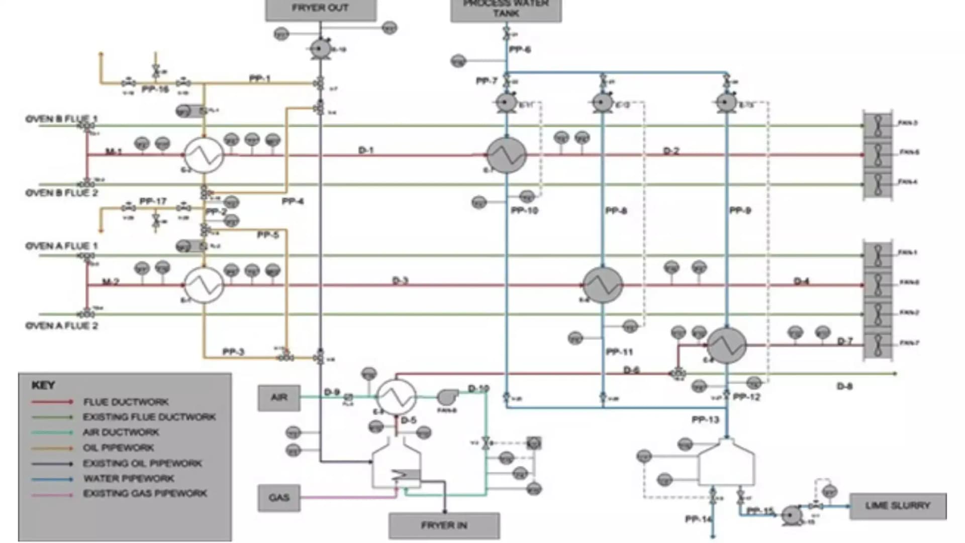
Process Integration And Pinch Analysis
Process integration is a highly effective, systems-oriented approach to designing and operating industrial facilities. By looking at a production site holistically rather than as isolated unit operations, it identifies opportunities to minimise energy consumption, water usage, and raw material waste.
At its heart lies Pinch Analysis. This guide explores how industrial facilities can systematically map thermal energy flows, design optimal heat exchanger networks, and achieve substantial utility savings.
What is Process Integration?
Historically, industrial process plants were designed by sizing individual unit operations—such as reactors, distillation columns, and evaporators—independently. Utilities like steam, hot oil, cooling water, and refrigeration were then supplied to each unit as needed. Though simple, this approach overlooks the massive potential for thermal energy exchange between different parts of the process.
Process integration shifts the focus to the entire system. It recognises that one part of a plant often rejects heat (requiring cooling utilities) while another simultaneously requires heating. Coupling these thermodynamic sources and sinks directly can drastically reduce external energy requirements.
Fundamentals of Pinch Analysis
Pinch analysis is a systematic method for optimising and maximising heat recovery systems across industrial processes, thereby minimising energy consumption. Originally developed in the late 1970s by Bodo Linnhoff and his colleagues, it provides a rigorous thermodynamic framework to determine the exact minimum energy targets for any process before designing the heat exchanger network.
Stream Identification: Hot vs. Cold
The first step in any pinch study is to categorise every thermal process stream:
- Hot Streams: Fluids requiring cooling (e.g. reactor product streams, distillation column overheads, or flue gases) which act as heat sources.
- Cold Streams: Fluids requiring heating (e.g. feed streams, boiler feed water, or distillation column bottoms) which act as heat sinks.
For each stream, the total heat flow rate (Q) is determined by the following thermodynamic relationship:
Q=m˙Cp(Tin−Tout)Where:
- Q is the thermal energy flow rate (kW)
- m˙ is the mass flow rate (kg/s)
- Cp is the specific heat capacity (kJ/kg·K)
- Tin is the inlet (supply) temperature (°C)
- Tout is the outlet (target) temperature (°C)
If Tin>Tout, the stream is hot (Q is positive, representing available heat). If Tin<Tout, it is cold (Q is negative, representing required heat).
Key Concepts of Pinch Analysis
Engineers rely on several core concepts to identify the absolute limits of energy recovery.
1. Minimum Temperature Approach (ΔTmin)
Heat transfer requires a driving force. The minimum temperature approach, ΔTmin, is the smallest temperature difference allowed between a hot and cold stream inside any heat exchanger.
- A smaller ΔTmin increases heat recovery but requires larger heat exchanger surface areas, raising capital expenditure.
- A larger ΔTmin reduces heat exchanger sizes but increases utility consumption, raising operating costs.
- Typically, ΔTmin ranges between 5 °C and 20 °C for chemical plants, and 10 °C to 30 °C for food processes.
2. Composite Curves
Combining the temperature-enthalpy (T-H) profiles of all hot streams into a single Hot Composite Curve, and all cold streams into a single Cold Composite Curve, allows engineers to plot them together on a single graph.
The region where these curves overlap represents the potential for process-to-process heat recovery, whilst the remaining gaps at either end dictate the minimum external heating and cooling utilities required.
3. The Pinch Point
The point where the curves come closest together is the Pinch Point (or simply 'the pinch'). This temperature divides the process into two separate thermodynamic regions:
- Above the Pinch: Net-deficient in heat, requiring only hot utilities.
- Below the Pinch: Heat surplus, requiring only cold utilities.
The Golden Rules of Pinch
To achieve maximum possible heat recovery, designers must strictly adhere to three thermodynamic rules:
- Do not transfer heat across the pinch (doing so increases both hot and cold utility requirements by exactly that amount of heat).
- Do not use cold utilities above the pinch.
- Do not use hot utilities below the pinch.
Case Study: Food Manufacturing Site Process Integration
Consider how these principles apply to a representative food processing site operating at a continuous production capacity of 12 tonnes per hour. The facility's utility infrastructure comprises a 1.2 MW steam boiler operating at 8 barg and a centralised ammonia refrigeration system with a cooling capacity of 850 kW. The objective of the pinch analysis is to systematically evaluate the thermal energy distribution across all processing lines and identify opportunities to recover waste heat.
The Challenge
Food manufacturing facilities are highly energy-intensive, requiring high temperatures for cooking, pasteurisation, and clean-in-place (CIP) systems, whilst simultaneously demanding low temperatures for refrigeration and product cooling. This makes them ideal candidates for comprehensive process integration.
The Engineering Methodology
The engineering team followed a structured, data-driven methodology:
- Data Gathering: Stream data was queried from site databases, supplemented by physical measurements where gaps existed.
- Stream Mapping: Process streams were fully mapped, establishing thermodynamic targets and allowing the modelling of various network designs.
- Network Synthesis: Designers systematically paired hot pasteuriser discharge lines and oven exhausts with incoming cold water feeds and CIP make-up loops.
| Stream Name | Stream Type | Supply Temp (Tin / °C) | Target Temp (Tout / °C) | Mass Flow Rate (m˙ / kg/s) | Specific Heat Capacity (Cp / kJ/kg·K) |
|---|---|---|---|---|---|
| CIP Water Feed | Cold | 15 | 85 | 2.5 | 4.18 |
| Pasteuriser Out | Hot | 90 | 30 | 3.0 | 4.18 |
| Boiler Feed Water | Cold | 12 | 80 | 1.8 | 4.18 |
| Oven Exhaust | Hot | 140 | 60 | 5.0 | 1.02 |
The Results
By identifying the optimal pinch point and designing an integrated heat exchanger network, the facility unlocked substantial operational savings. The highest-performing configuration achieved a payback period of 2.7 years, delivering gas and steam savings of 790 kW—equating to circa £125,000 per annum.
Key Benefits of Process Integration & Pinch Analysis
Implementing these methodologies offers several clear advantages for manufacturing operations:
- Substantial Energy Savings: Directly reduces fossil fuel consumption (gas or steam generation) and refrigeration/cooling loads.
- Carbon Footprint Reduction: Decreased energy use translates directly to lower greenhouse gas emissions, supporting corporate net-zero targets.
- Optimised Capital Expenditure: Before investing in larger boilers or cooling towers, pinch analysis can reveal if thermal integration can lower utility demands enough to defer or eliminate the procurement.
- Debottlenecking: Relieving thermal constraints on existing heat exchangers allows process lines to operate at higher throughputs without overloading utility infrastructure.
