Optimising Fan Power Consumption: Scaling Ductwork for CO2 Processing
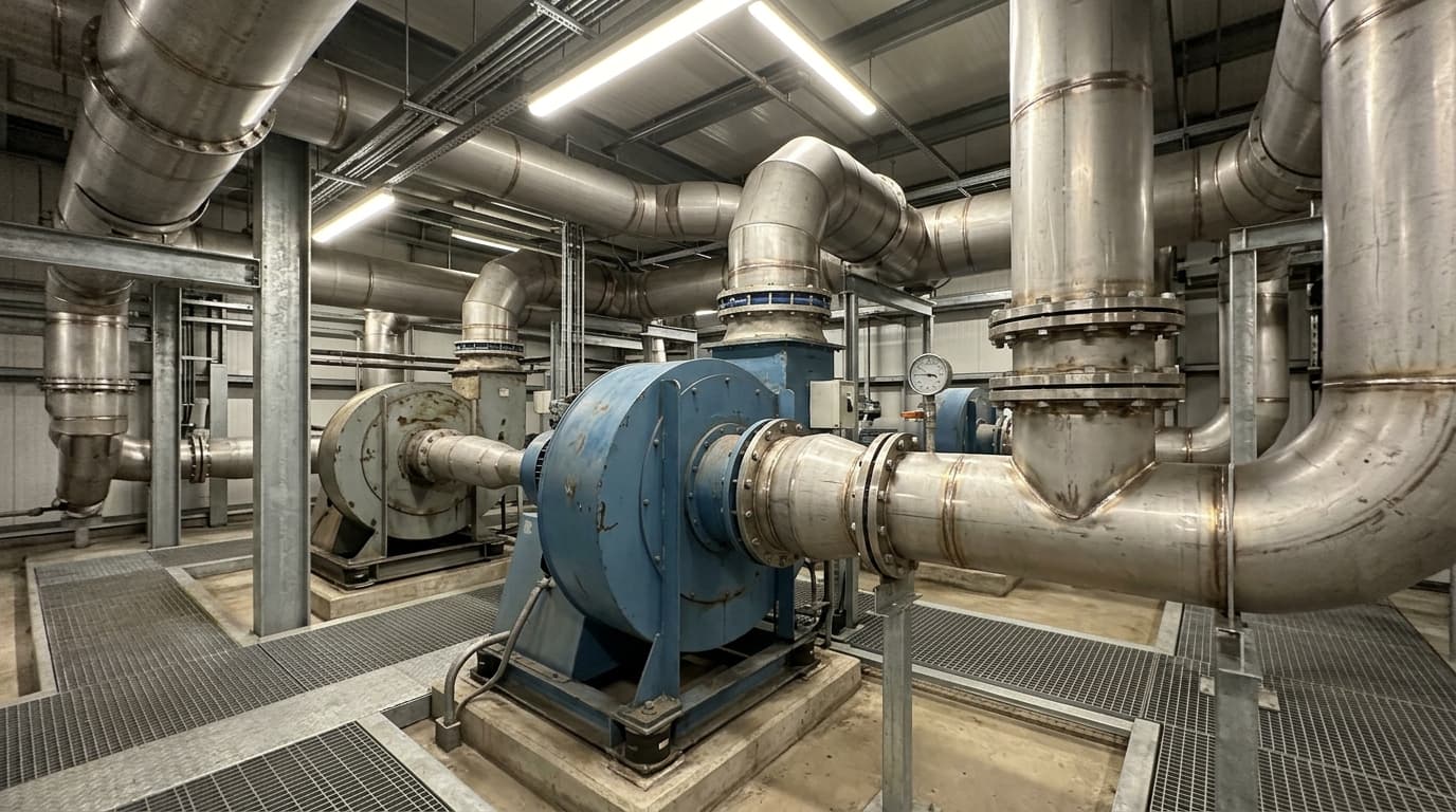
A sustainable industrial technology company required a critical performance assessment of a flue gas transport system to determine the fan specifications for a new processing installation. The facility needed to move 2,000 m³/hr of process gas through a series of thin-walled, uninsulated stainless steel pipes. The project necessitated a detailed calculation of system pressure drop to ensure the selected fan provided sufficient capacity to overcome resistance while operating within energy-efficient parameters.
The Engineering Challenge
The core objective was to determine the required fan power for varying pipe diameters to effectively transport the flue gas mixture. A significant variable in this assessment was the mixer—specifically, the CO₂ container—which presented an unknown resistance factor within the piping network.
The team was provided with historical flue gas data but lacked specific pressure drop information for the mixer unit itself. Furthermore, the project required an evaluation of three different ductwork sizes to identify the most efficient configuration. The client specified that the fan must be located post-mixer, near the CO₂ container, and must include a 15% spare capacity buffer to account for unforeseen system resistance.
Engineering Methodology
To provide accurate fan sizing, the reporting engineer conducted a series of simulations using the technical ductwork calculation report as the primary reference. This process involved assessing different ambient conditions—specifically 8°C and 28°C—to determine the impact of temperature fluctuations on air density, velocity, and the resulting system DP (differential pressure).
The study utilised data from the previous technical simulation report, which employed CFD to estimate the pressure drop through the CO₂ container. By integrating this estimated pressure drop with the calculated resistance of the pipework and bends, the team was able to model the system performance across three nominal pipe sizes:
- 212 mm (ID)
- 315 mm (ID)
- 397 mm (ID)
Each simulation assumed a fixed flow rate of 2,000 m³/hr, with the mixer outlet temperature maintained at 70°C. The configuration allowed the engineering team to isolate the impact of pipe diameter on the final fan motor requirements.
Analysis of Findings
The simulations revealed that the pipe diameter was the most significant factor influencing fan size after the primary flow requirement. While the pressure drop at the mixer remained relatively consistent regardless of flow variations, the choice of pipework had a compounding effect on the overall system pressure drop. This, in turn, dictated the necessary power input for the fan motor.
The table below summarises the results for the various pipe configurations tested, maintaining the required 15% spare capacity for safe operation.
| Pipe ID (mm) | System DP (mbar) | Spare Capacity (%) | Final Fan Size (kW) |
|---|---|---|---|
| 212 | 35 | 15 | 2.2 |
| 315 | 15 | 15 | 0.9 |
| 397 | 12 | 15 | 0.8 |
The analysis confirmed that increasing the pipe diameter significantly reduced the required fan power. Specifically, moving from a 212 mm pipe to a 397 mm pipe reduced the final fan power requirement from 2.2 kW to 0.8 kW, illustrating the direct correlation between duct sizing and operational energy consumption.
Outcomes and Recommendations
The engineering consultancy firm successfully provided the client with the precise fan sizing data required for the installation. The final design recommendation was based on the 2,000 m³/hr flow requirement, resulting in a recommended fan size of 2.2 kW for the 212 mm pipe configuration. This configuration ensures the system meets the operational flow demands while accounting for the necessary safety margins.
The reporting engineer also noted that if the client intended to scale the process flow, the power requirements increase non-linearly. For instance, at 6,000 m³/hr using a 212 mm pipe, the power requirement would escalate to 29 kW with a 188 mbar system DP. This report has enabled the project recipient to make informed decisions regarding capital expenditure for fans versus operational expenditure for ongoing energy usage, balancing pipe diameter choices against future system expansion goals.

Managing Director — EnerTherm Engineering
Dr. François Pierrel is Managing Director of EnerTherm Engineering with over two decades of expertise in thermal design, heat transfer, and industrial energy optimisation. He holds a PhD in Heat Transfer from Cranfield University and a Post-Doctorate from Heriot-Watt University.
