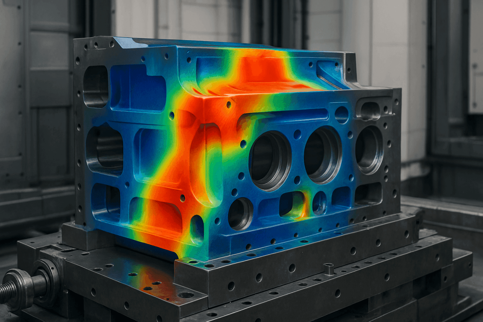
Predicting Thermal Distortion in Large-Scale Manufacturing Equipment
Thermal distortion is a significant challenge in large-scale manufacturing because a small temperature difference can produce displacement comparable with a machine’s positioning tolerance. For example, a 1 m steel member with a coefficient of thermal expansion of approximately 12 µm/m·°C changes length by about 120 µm for a 10 °C uniform change; a gradient through the member can also cause bending. Uneven temperature distributions cause different parts of a structure to expand or contract by different amounts, producing deformation and internal stress.
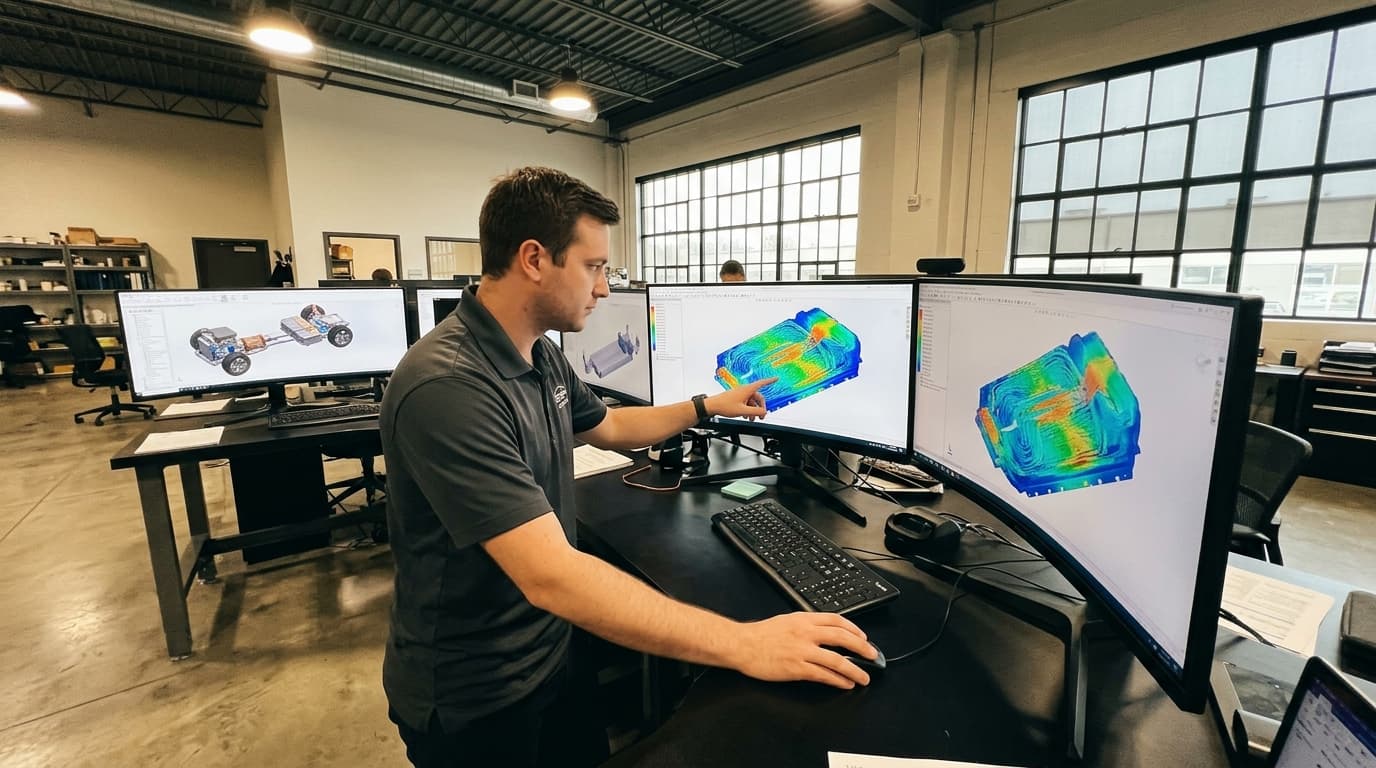
Detailed thermal analysis using CFD and FEA to predict temperature distributions, heat transfer rates, and thermal stresses before you build or modify equipment.
Understanding Thermal Distortion
Thermal distortion is deformation caused by a temperature change or, more commonly in industrial equipment, a temperature gradient. A uniformly heated, unconstrained component may expand without significant distortion; distortion occurs when temperatures are non-uniform, materials respond differently or supports prevent free movement.
For a simple, unconstrained member, thermal strain is commonly estimated as:
εth=αΔTWhere εth is thermal strain, α is the coefficient of thermal expansion, and ΔT is the change in temperature. In real equipment, joints, variable section thicknesses, non-uniform heating and restraints mean this expansion is rarely uniform.
A 1 m Invar 36 member, with a typical 20–100 °C expansion coefficient of about 1.2 µm/m·°C, changes length by roughly 12 µm over 10 °C; ordinary steels are commonly about 11–15 µm/m·°C over that range. NIST’s thermal-expansion reference documents the markedly lower expansion of 36 % nickel Invar alloys. The relevant design quantity is often relative movement between functional datums, rather than the absolute expansion of an isolated part.
In manufacturing equipment, thermal distortion can stem from several sources:
- Heat Sources: Operating machinery, friction, motors, cutting processes, welding arcs, furnaces, electronics and environmental factors can generate heat, creating temperature gradients within equipment. A 1 kW spindle motor or a 5 kW welding arc need not transfer all its heat into the structure for measurable error to occur: a small asymmetric fraction can establish a persistent gradient.
- Material Properties: Different materials expand and contract at varying rates when subjected to temperature changes. A 1 m aluminium member at approximately 23 µm/m·°C expands about 230 µm for a 10 °C change, roughly twice the movement of a typical steel member of the same length.
- Design Constraints: Complex geometries, bolted interfaces, welded joints, guideways and structural constraints can exacerbate thermal distortion by restricting free expansion and contraction. For a fully restrained elastic member, a first screening estimate of thermal stress is σ≈EαΔT; using steel values of E=200 GPa, α=12×10−6/°C and ΔT=10 °C gives approximately 24 MPa before allowing for joint compliance or yielding.
- Transient Operating Conditions: Start-up, shutdown, rapid heating, intermittent duty cycles and cooling-system changes can create short-term gradients more severe than steady-state conditions. A machine may meet a steady-state positional specification yet drift during the first 30–60 minutes of operation.
- Environmental Variation: Changes in ambient temperature, sunlight, draughts and local HVAC performance can affect large frames, measuring systems and precision tooling. NIST laser-tracker testing uses 0.2 °C temperature control and applies 0.01 °C temperature measurements when establishing traceable ranging performance, illustrating the scale at which environmental variation matters to precision measurements. NIST
Thermal distortion can manifest in several ways:
- Dimensional Inaccuracies: Changes in dimensions can lead to misalignment and reduced precision in manufacturing processes.
- Geometric Error: A machine bed may bow, a spindle axis may drift, or a fixture may move relative to a datum even when individual component dimensions remain within tolerance.
- Stress Concentrations: Uneven expansion and contraction can create localised stress concentrations, potentially leading to premature failure, cracking or fatigue.
- Performance Degradation: Thermal distortion can affect bearings, gears and optical elements, reducing efficiency and accuracy.
- Assembly and Seal Problems: Distorted flanges, housings and joints can compromise sealing, bearing preload, gear mesh or component clearances.
Methods for Predicting Thermal Distortion
Accurately predicting thermal distortion is essential when designing robust manufacturing equipment. The best approach usually combines rapid calculations for early decisions, simulation for detailed design and measurement for validation.
Finite Element Analysis (FEA)
FEA is a numerical technique for simulating structures under thermal loads. FEA software divides a structure into elements and solves for the temperature distribution, stress and deformation. It is useful where the temperature field, material behaviour or restraint conditions are too complex for a hand calculation.
FEA is particularly useful for:
- Complex Geometries: FEA can handle intricate shapes and assemblies that are difficult to analyse using analytical methods.
- Non-Linear Material Behaviour: FEA can account for properties that vary with temperature, including thermal expansion coefficient, thermal conductivity, elastic modulus and yield strength.
- Thermo-Mechanical Coupling: FEA can calculate the structural response to a mapped temperature field, including thermal stress and movement at functional interfaces.
- Contact and Assembly Effects: Models can represent bolted joints, sliding interfaces, preload and contact conductance, which influence heat flow and expansion through an assembly.
- Transient Thermal Behaviour: Time-dependent analysis can identify distortion during warm-up, production cycles and cooling, rather than only at steady state.
FEA simulations typically involve the following steps:
- Model Creation: A detailed 3D model of the equipment is created, including relevant components, interfaces and materials.
- Definition of Inputs: Heat sources, operating cycles, convection, radiation, coolant flow, ambient conditions and support conditions are defined using measured data where possible. Heat input should be expressed in watts or watts per unit area, and coolant conditions should include supply temperature, flow rate and heat capacity.
- Thermal Analysis: A thermal analysis determines the temperature distribution, considering heat sources, boundary conditions and temperature-dependent material properties.
- Structural Analysis: The temperature distribution from the thermal analysis is applied as a load in a structural analysis, which calculates stress, rotation and deformation.
- Result Interpretation: Results are assessed against functional limits, such as spindle-nose displacement in µm, angular error in µrad or mrad, bearing-clearance change in µm, and misalignment at an assembly interface.
- Correlation and Refinement: Predicted temperatures and displacements are compared with test measurements, then the model is refined before design decisions are finalised.
Model quality depends principally on boundary conditions and material data. A highly detailed mesh cannot compensate for an unrealistic heat load, convection coefficient or mounting stiffness. Engineers should refine heat paths, joints, critical interfaces and features that establish functional alignment.
Analytical Methods
Analytical methods use mathematical equations to predict thermal distortion. They are faster than FEA but are limited to relatively simple geometries and loading conditions. They are useful for establishing the scale of likely movement before committing to a detailed model.
Analytical methods can be useful for:
- Preliminary Design: Providing quick estimates of thermal distortion during the initial design phase.
- Tolerance Allocation: Estimating expansion of rails, shafts, frames or tooling so that clearances and compensation ranges can be specified realistically. For example, a 2 m steel rail subject to a 3 °C average rise expands by approximately 72 µm if unconstrained.
- Validation: Verifying FEA results for simple cases, such as a prismatic member with a measured uniform temperature change.
- Parametric Studies: Evaluating the effect of material choice, component length and operating temperature on thermal distortion.
These methods should distinguish between free and restrained expansion. A free member may move without developing high stress, whereas a restrained member can generate substantial thermal stress even where visible displacement is limited.
Experimental Methods
Experimental methods involve measuring thermal distortion directly using instruments such as strain gauges, thermocouples and laser displacement sensors. Measurement is needed because operating equipment includes heat losses, contact conductance, assembly variation and operator behaviour that may not be fully represented in a simulation.
Experimental methods are valuable for:
- Validating Simulation Results: Providing measured temperature and displacement data against which FEA and analytical predictions can be checked.
- Identifying Unexpected Behaviour: Detecting effects such as asymmetric coolant flow or heat transfer through cables and supports.
- Material Characterisation: Determining thermal and mechanical properties under operating conditions.
- Machine Acceptance Testing: Establishing warm-up time, repeatability and positional drift under representative production loads.
Useful test plans measure both cause and effect: temperatures at heat sources, interfaces and ambient locations, together with displacement or alignment at functional datums. The measurement system must resolve substantially less than the permitted movement. As a reference, NIST reports an expanded uncertainty of $(5 + 0.3L)$ µm, with L in metres, for calibrated laser-tracker ranging measurements. NIST Laser trackers, capacitance probes, dial indicators, optical measurement systems and calibrated artefacts can all be appropriate depending on the required resolution and operating environment.
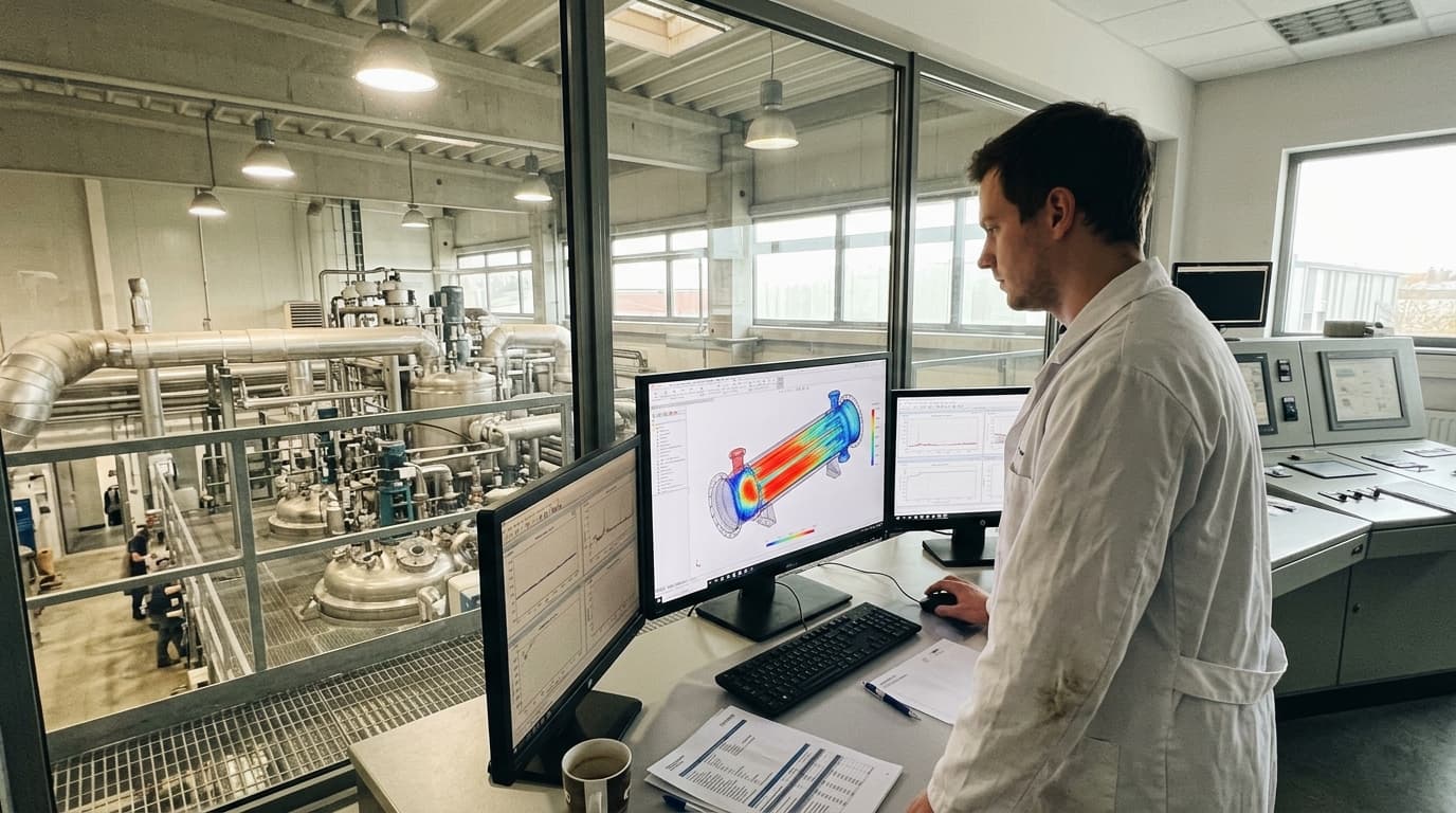
Detailed thermal analysis using CFD and FEA to predict temperature distributions, heat transfer rates, and thermal stresses before you build or modify equipment.
Strategies for Minimising Thermal Distortion
Once thermal distortion has been predicted, several strategies can minimise its impact. The most effective solutions address the temperature gradient and the structure’s sensitivity to it, rather than relying on post-process correction alone.
Thermal Management
Effective thermal management reduces temperature gradients and resulting distortion. Strategies include:
- Heat Sinks: Using heat sinks to dissipate heat from critical components.
- Forced Convection: Employing fans or blowers to increase heat transfer, while avoiding a one-sided air stream across a precision frame.
- Liquid Cooling: Utilising liquid coolants to remove heat from high-temperature areas; the design calculation should include heat load, coolant flow rate, supply temperature and allowable return-temperature rise.
- Thermal Insulation: Insulating components to reduce unwanted heat transfer and maintain uniform temperatures.
- Optimising HVAC Systems: Designing heating, ventilation and air conditioning (HVAC) systems to regulate temperature within manufacturing environments.
- Balanced Cooling Circuits: Routing coolant symmetrically and controlling flow rate, supply temperature and return temperature so one side of a frame or housing is not cooled more aggressively than the other.
- Thermal Barriers: Isolating heat-generating motors, gearboxes and electronics from precision structures while retaining a predictable path for heat rejection.
Cooling capacity alone is insufficient. An uneven cooling arrangement can introduce as much thermal distortion as the original heat source. Temperature stability and symmetry should be assessed at the machine’s critical reference points.
Material Selection
Choosing materials with low coefficients of thermal expansion can reduce thermal distortion. Consider using:
- Invar: A 36 % nickel–iron alloy whose typical coefficient is about 1.2 µm/m·°C between 20 °C and 100 °C, compared with approximately 11–15 µm/m·°C for ordinary steels. NIST
- Ceramics: Materials with high stiffness and, for many engineering grades, lower expansion than aluminium or conventional steel; suitability depends on fracture toughness, joining method and operating temperature.
- Composites: Fibre-reinforced composites can be tailored for low expansion in the fibre direction, but their directional conductivity and expansion must be included in the model.
- Compatible Material Pairs: Selecting materials with similar expansion behaviour for bonded, bolted or welded assemblies can reduce differential movement and joint stress.
Material selection must balance expansion against stiffness, thermal conductivity, machinability, corrosion resistance, cost and operating temperature. A low-expansion material is not automatically the best solution if it creates a sharp local temperature gradient or an impractical joint with neighbouring components.
Design Optimisation
Optimising manufacturing equipment can minimise thermal distortion by:
- Symmetrical Design: Designing structures with symmetrical shapes and heat paths to promote uniform temperature distribution.
- Stress Relief Features: Incorporating expansion joints and flexible couplings to accommodate thermal expansion and contraction.
- Minimising Constraints: Reducing constraints on thermal expansion to allow components to expand and contract freely.
- Balancing Cross Sections: Designing parts with balanced cross sections to reduce differential heating and cooling.
- Defining a Thermal Datum: Locating precision features and measurement references so predictable expansion occurs away from the most critical alignment relationship.
- Separating Structural and Heat-Generating Functions: Mounting heat-generating components to limit direct heat transfer into guideways, metrology frames or precision tooling.
Support conditions deserve particular attention. Over-constraining a long member can convert normal thermal expansion into bending or high stress. Kinematic mounting principles can allow controlled movement while retaining repeatable location.
Process Control
Controlling manufacturing processes to minimise heat generation and maintain stable temperatures can also reduce thermal distortion:
- Optimising Machining Parameters: Adjusting cutting speed, feed rate and depth of cut to manage cutting heat; the selected parameters should be validated against measured tool, workpiece and coolant temperatures.
- Controlling Welding Processes: Specifying heat input, travel speed, sequence, fixturing and interpass temperature to control transient gradients and residual stress.
- Implementing Lean Heat Treatment: Using low-pressure carburising (LPC) and high-pressure gas quenching (HPGQ) only where trials demonstrate that the selected alloy, case depth, load arrangement and quench conditions meet the required distortion limit.
- Part Orientation: Orienting parts consistently within the furnace and controlling load spacing so heating and quenching are repeatable.
- Clamp & Temper Method: Clamping and tempering components after heat treatment where process qualification shows that this reduces the relevant permanent distortion without unacceptable residual stress.
- Controlled Warm-Up: Establishing a repeatable warm-up sequence before precision production or calibration, allowing equipment to reach a specified thermal condition.
- Monitoring Process Drift: Recording temperatures, coolant conditions and dimensional results to detect thermal drift before it produces out-of-tolerance parts.
For heat treatment and welding, residual stress and phase transformation can contribute to permanent distortion as well as reversible thermal movement. Process models and trials should therefore evaluate the complete heating and cooling cycle.
Simulation and Modelling
Simulation and modelling can quantify the response to measured heat loads and boundary conditions.
- Thermo-Mechanical Analysis: Conduct thermo-mechanical FEA using temperature-dependent material data and validated support conditions.
- Computational Fluid Dynamics (CFD): Use CFD where coolant or air-flow distribution controls the temperature field; report local coolant temperature, flow distribution and heat-transfer coefficients rather than only total cooling capacity.
- Sensitivity Studies: Vary heat input, ambient conditions, coolant temperature, material properties and contact resistance to identify assumptions that most affect displacement at the functional datum.
- Compensation Models: Use measured or simulated thermal drift to inform machine-control compensation where design changes cannot eliminate residual error.
Simulation results should be reported in functional terms: displacement at a spindle nose, angular change at a guideway, variation in bearing clearance or misalignment at an assembly interface. This links thermal distortion directly to manufacturing capability and tolerance requirements.
Case Studies and Examples
Several published studies demonstrate these methods in practice:
- Solar Dynamic Concentrators: NASA modelled the Space Station Freedom solar dynamic concentrator by mapping thermal loads into structural FEA and evaluating the resulting facet displacement, slope error and receiver flux. For a typical orbit, the analysis predicted facet rotations below 0.2 mrad, thermal-flattening radius change below 5 %, and power loss below 0.3 %. NASA Technical Memorandum 102504
- Vehicle Body Painting: Nippon Steel modelled thermal distortion of vehicle outer panels during electrodeposition-paint drying by representing both the body’s oven deformation and the curing behaviour of structural filler between the outer panel and reinforcement. The work identifies filler thermosetting behaviour as a mechanism that changes panel distortion during the hot-air drying cycle, rather than treating the panel as a freely heated sheet. Nippon Steel Technical Report No. 122
- Case-Hardened Gears: A simulation-and-experimental study of 8620H steel drive gears reduced runout by 70.0–76.9 % from the original heat-treatment process. The result demonstrates that distortion control depends on the full carburising and quenching process, including transformation strain and cooling conditions, not simply furnace temperature uniformity. Chinese Journal of Mechanical Engineering
- Laser Powder Bed Fusion: NIST’s additive-manufacturing metrology programme produces benchmark datasets containing in-situ temperature and cooling-rate measurements together with post-process distortion, residual stress and microstructure. These datasets allow thermal models to be checked against measured cause-and-effect data instead of relying only on nominal laser power and scan-path inputs. NIST
- Machine-Tool Thermal Drift Measurement: NIST has conducted machine-tool thermal-drift monitoring using periodic image analysis to determine three-dimensional thermal error at target locations inside a machine. The mechanism under investigation is relative motion of the machine’s functional geometry during changing thermal conditions, which control compensation and structural redesign must address. NIST dataset description
These examples show that thermal distortion affects large welded frames, precision machine tools, heat-treated gears and additive builds. The same discipline applies: identify heat sources and heat paths, predict the temperature field, evaluate structural response and verify the solution under representative operating conditions.
Conclusion
A quantified thermal budget—heat loads, allowable temperature gradients, predicted displacement and measurement uncertainty—allows manufacturers to set practical tolerances and select appropriate cooling, materials, mounting arrangements and compensation.
Enertherm Engineering’s thermal design simulation services can identify potential issues and optimise designs for performance and reliability. Contact us today to learn more: https://enertherm-engineering.com/thermal-design-simulation.
