Beyond the Stack: Harnessing Flue Gas Heat for Sustainable Industrial Futures
For centuries, the iconic plumes rising from industrial smokestacks have been symbols of progress, yet they are also silent witnesses to a colossal waste: vast amounts of thermal energy vanishing into the atmosphere. This dissipated heat, often reaching hundreds of degrees Celsius, represents not merely a lost resource but a tangible burden—an increased carbon footprint and higher operational costs. While seemingly an inevitable byproduct of combustion, this narrative of waste is rapidly changing. Across the industrial manufacturing and power generation sectors, the sophisticated application of flue gas heat recovery (FGHR) is transforming this environmental liability into an invaluable asset, driving unprecedented gains in energy efficiency and significantly advancing corporate sustainability goals.
What is Flue Gas Heat Recovery?
To understand the mechanics of industrial efficiency, one must first address a fundamental question: what is flue gas heat recovery?
In industrial thermodynamics, flue gas heat recovery is the process of capturing thermal energy from the exhaust gas streams of combustion processes before they are discharged into the atmosphere. This captured energy is then redirected back into the plant's thermal cycle, preheating fluids, generating steam, or powering auxiliary systems. By intercepting these high-temperature streams, facilities can dramatically reduce their reliance on primary fuel sources.
The heat content of industrial flue gases is broadly categorised into two distinct thermodynamic forms:
- Sensible Heat: The thermal energy associated with the temperature difference of the gas stream. This is recovered by cooling the hot flue gas without causing a phase change in its constituents.
- Latent Heat: The thermal energy bound up within the water vapour produced during combustion (particularly when burning hydrogen-rich fuels like natural gas). This heat is unlocked and recovered only when the flue gas is cooled below its dew point, causing the water vapour to condense into liquid phase.
The typical sequence of a multi-stage flue gas heat recovery system is illustrated in the process flow below:
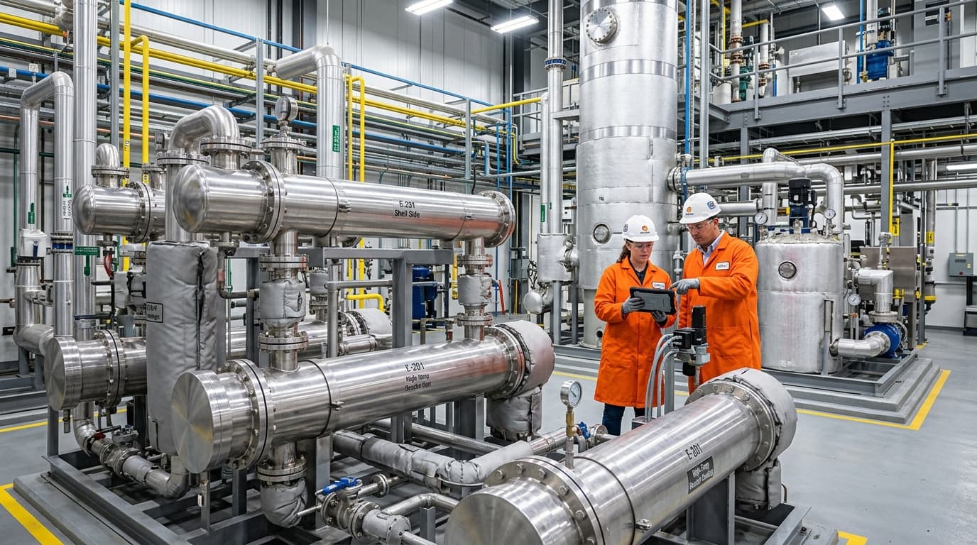
Recover waste heat and cut fuel costs with shell & tube or air-to-air exchangers engineered for continuous industrial duty.
The Untapped Potential of Industrial Exhaust
At its core, waste heat recovery from flue gases is a discipline rooted in chemical engineering, mechanical engineering, and heat transfer principles. It involves capturing the thermal energy contained within the hot exhaust gases generated by industrial processes and repurposing it for beneficial use. Whether from furnaces, boilers, kilns, or turbines, these high-temperature gases represent a substantial portion of an operation's total energy input that is traditionally discarded.
Consider a typical industrial boiler. Even the most efficient modern condensing boilers, while incorporating some internal heat recovery, still vent a significant amount of heat with their flue gases. Older systems are even less efficient, with some estimates suggesting up to 20% of combustion energy is lost through flue gas. This overlooked opportunity is immense; studies indicate that systematic waste heat recovery projects can yield annual energy cost savings of 10% to 20%. Some sources even suggest that up to 20-50% of energy in metal and non-metallic minerals manufacturing is lost as waste heat, highlighting the scale of the potential.
Quantifying Heat Recovery Potential
To evaluate the feasibility of flue gas heat recovery, engineers calculate the total available thermal energy (Q) within the gas stream. The sensible heat recovery rate is determined using the following thermodynamic formula:
Q=m˙⋅Cp⋅(Tin−Tout)Where:
- Q is the sensible heat recovery rate in kilowatts (kW)
- m˙ is the mass flow rate of the flue gas in kilograms per second (kg/s)
- Cp is the mean specific heat capacity of the flue gas in kilojoules per kilogram-Kelvin (kJ/kg·K)
- Tin is the inlet temperature of the flue gas before the heat exchanger (K or °C)
- Tout is the target outlet temperature of the flue gas after recovery (K or °C)
For systems that lower the flue gas temperature below the dew point, the latent heat component (Qlatent) must also be calculated to determine the total energy yield:
Qlatent=m˙w⋅hfgWhere:
- m˙w is the rate of water vapour condensation in kilograms per second (kg/s)
- hfg is the latent heat of vaporisation of water, approximately 2260 kJ/kg at standard atmospheric pressure
By executing these calculations, industrial operations can precisely model the return on investment (ROI) of retrofitting flue gas heat recovery systems.
The Triple Bottom Line: Economic, Environmental, and Operational Benefits
The implementation of flue gas heat recovery systems delivers a compelling ‘triple bottom line’ impact: significant economic savings, profound environmental benefits, and tangible operational improvements.
Economic Advantages: Fueling Profitability
The financial incentives for adopting FGHR are substantial and often provide rapid returns on investment. By capturing and reusing waste heat, industries dramatically reduce their reliance on primary energy sources, leading to a direct decrease in fuel consumption and associated costs. This translates into considerable savings on electricity or fuel bills, enhancing overall profitability and fostering competitive advantages.
Payback periods for these projects often range from a remarkable 6 to 18 months. For instance, a heat recovery system installed by a branded foods manufacturer reduced greenhouse gas emissions by 1,750 tonnes annually, showcasing direct savings alongside environmental gains. A refinery heating furnace, by reducing flue gas temperature from 180°C to 20-40°C, achieved energy savings of 12.5-16.9% and carbon emission reductions of 13.7-18.3%.
Environmental Stewardship: Cutting Emissions and Footprints
Beyond immediate financial gains, waste heat recovery from flue gases contributes significantly to environmental sustainability. By reducing the demand for primary energy, these systems lead to a proportional decrease in greenhouse gas emissions, including carbon dioxide (CO₂), and other pollutants associated with energy generation. This aligns directly with global efforts to mitigate climate change, promote energy efficiency, and reduce the overall carbon footprint of industrial operations.
Power plants employing combined heat and power (CHP) systems, often utilising flue gas heat recovery, can achieve thermal efficiencies of up to 80%, substantially reducing emissions compared to traditional methods. One analysis on a 900 MWe steam power unit demonstrated that flue gas heat recovery could reduce CO₂ emissions by 22,810 tonnes per year and fuel demand by 26,727 tonnes per year, leading to annual savings of €500,000 to €1,000,000.
Operational Enhancements: Boosting Efficiency and Reliability
Implementing waste heat recovery also offers tangible operational improvements. Preheating combustion air, process water, or other process streams with recovered heat can lead to improved overall process performance and productivity.
For every 22°C reduction in flue gas temperature through an air pre-heater, there can be a 1% saving of fuel in the boiler. Similarly, increasing combustion air temperature by 20°C can increase heating system efficiency by 1%. This enhanced efficiency also leads to a reduction in the volume of flue gas, allowing for smaller sizes of associated equipment like fans, stacks, and ducts, which in turn reduces auxiliary energy consumption.
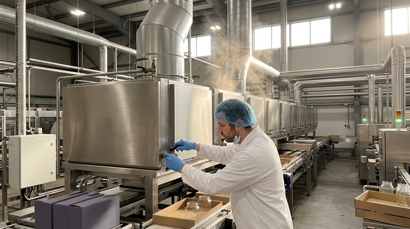
Our ThermStack and EcoStream heat exchanger ranges deliver measurable energy savings across chemical, food, pharma, and power generation processes.
Key Technologies and Applications in Flue Gas Heat Recovery
The methods for recovering waste heat from high-temperature flue gases are diverse, each tailored to specific industrial needs and temperature ranges.
Heat Exchangers: The Core of Recovery
Heat exchangers are the most common and fundamental devices for flue gas heat recovery. They work by transferring thermal energy from the hot flue gas to a cooler working medium, such as water, thermal oil, or air.
- Recuperators: These are non-contact heat exchangers where heat is transferred between two fluids without direct mixing, often used for preheating combustion air. They are typically made of metallic alloys for medium temperatures or ceramic materials for high-temperature applications exceeding 1000°C.
- Waste Heat Boilers: A specialised type of heat exchanger designed to convert waste heat from high-temperature flue gases directly into steam for industrial processes or power generation. These are particularly suitable for large-scale energy recovery in refineries and chemical complexes.
- Economisers: Gas-to-liquid heat exchangers that recover heat from flue gases (optimally above 150°C) to preheat liquids like boiler feedwater or process water, directly reducing fuel requirements.
- Condensers: Operating at lower temperatures (from 80°C), condensing heat exchangers cool flue gases below their acid and water dew points, causing water vapour to condense and release latent heat. This recovered heat can be used for low-temperature applications like process water or boiler feedwater preheating, and can significantly improve boiler efficiency, sometimes up to 95% in combined heat and power applications. They also help reduce moisture and particulate emissions.
Advanced Heat Recovery Systems
Beyond conventional heat exchangers, several advanced technologies enhance FGHR capabilities:
- Organic Rankine Cycle (ORC) Systems: These systems convert waste heat, even from lower temperature flue gases, into electricity by using an organic working fluid with a lower boiling point than water. The fluid evaporates and expands through a turbine to generate clean electrical power.
- Absorption Refrigeration Systems: Flue gas waste heat can power absorption chillers (using lithium bromide-water or ammonia-water cycles) for industrial cooling or air conditioning, offering a low-emission alternative to conventional electrical compressors.
- Heat Pipes: These highly efficient, closed-loop thermal conduction devices transfer heat via the evaporation and condensation of an internal working fluid. They offer high heat transfer rates with minimal temperature drops and are highly flexible for specialised configurations.
Broad Industrial Applications
Flue gas heat recovery technology has demonstrated remarkable effects in energy conservation and emission reduction across numerous energy-intensive industries:
- Power Generation: Especially in thermal power plants, recovering waste heat from saturated flue gases can reduce the need for turbine extraction steam and generate additional electricity.
- Heavy Industries (Cement, Steel, Glass): These sectors, major energy consumers, generate substantial high-temperature flue gas. Recovering this heat can lead to significant energy cost savings, often by preheating raw materials or generating power.
- Chemical Industry: Production processes frequently release large amounts of heat in flue gases, making them prime candidates for recovery to power downstream operations or improve process control.
- Food Processing: Recovered heat can be reused for sterilising equipment, pasteurisation, drying products, or even supporting refrigeration cycles.
- Oil and Gas Sector: Waste heat from gas flaring processes, gas turbines, and process heaters can be captured and repurposed to minimise environmental impact and meet strict emission standards.
Challenges and Considerations in Implementation
While the benefits are clear, implementing flue gas heat recovery systems involves specific challenges that require meticulous engineering and design:
- Corrosion Issues: The risk of flue gas temperatures dropping below the acid dew point (especially sulfuric acid in sulfur-bearing fuels, or hydrochloric acid in waste-to-energy plants) can cause aggressive, highly destructive acidic condensation. Engineers must mitigate this through precise thermal controls and by selecting corrosion-resistant materials such as high-grade stainless steel (e.g., 316L), Hastelloy, fluoropolymer coatings (PTFE), or borosilicate glass.
- Fouling and Dust Content: Flue gases often contain high levels of dust, fly ash, soot, and particulate matter. These materials accumulate on heat exchanger surfaces, creating an insulating layer that degrades heat transfer efficiency. Addressing this requires continuous online cleaning systems, such as soot blowers, acoustic horns, or mechanical scraping systems.
- Draft Loss and Pressure Drop: Integrating a heat exchanger into the exhaust path introduces flow resistance (pressure drop). If the existing stack draft is insufficient, this can restrict boiler combustion. To overcome draft loss, facilities often must upgrade or install induced draft (ID) fans.
- Space Constraints: Integrating new heat recovery equipment into existing facilities can be challenging due to limited space, necessitating careful structural planning and compact, modular heat exchanger designs.
- Variability of Waste Heat: Industrial processes can be batch-based or have fluctuating load conditions, leading to inconsistent waste heat availability. Modular systems and thermal energy storage solutions are being developed to address this.
The Future of Industrial Sustainability
Flue gas heat recovery is not just an auxiliary technology; it is a strategic imperative for industries striving for greater sustainability and economic resilience. As global energy costs fluctuate and environmental regulations tighten, the ability to harness otherwise wasted thermal energy becomes a critical competitive advantage.
The continued innovation in heat exchanger design, material science, and integration with advanced energy systems like Organic Rankine Cycles (ORC) will only broaden the applicability and efficiency of FGHR. For industrial leaders, investing in comprehensive energy audits and adopting these sophisticated heat recovery solutions is a clear path towards a more efficient, profitable, and environmentally responsible future.
