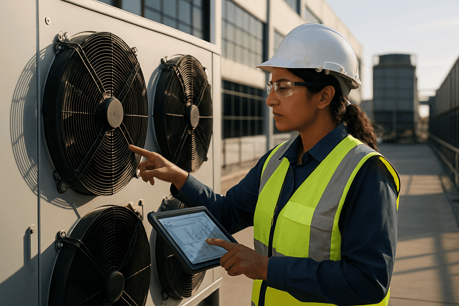
Key Design Considerations for Condensers in Data Center Cooling Applications
Data centres house vast arrays of servers and networking equipment that operate continuously. This intensive operation generates substantial thermal energy, making effective cooling solutions essential to prevent equipment failure and ensure optimal performance. Within these critical cooling infrastructures, the condenser plays a pivotal role, serving as the primary component for rejecting absorbed heat from the data centre environment to the ambient atmosphere. Optimising condenser design requires a deep understanding of thermodynamics, fluid dynamics, energy efficiency, and environmental constraints.
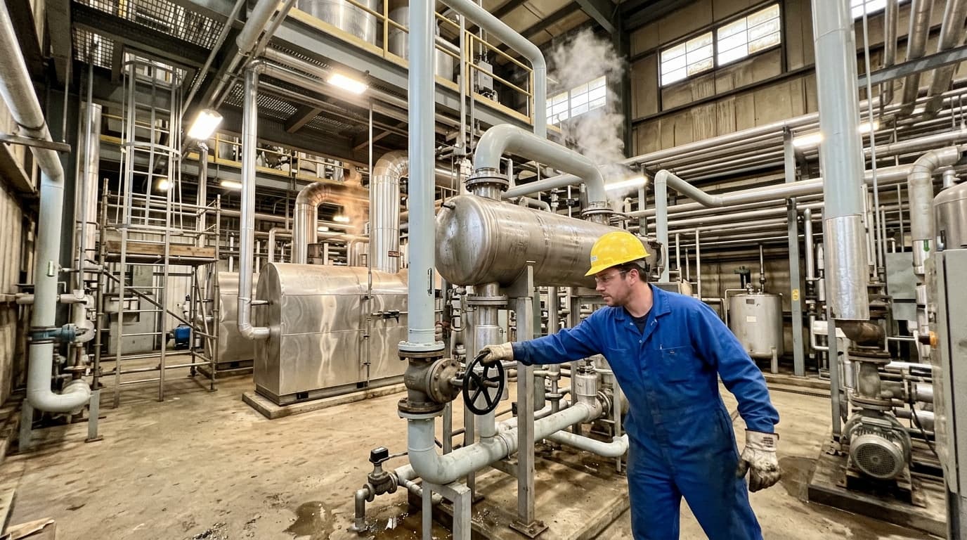
Capture latent heat from exhaust steam and process vapours — reducing water consumption and recovering energy that would otherwise be lost to atmosphere.
The Crucial Role of Condensers in Data Centre Cooling
At its core, a condenser is a phase-change heat exchanger within a refrigeration or air conditioning system. It takes superheated, high-pressure refrigerant vapour from the compressor and cools it, causing it to condense back into a liquid state while expelling the latent heat of vaporisation to an external sink (either air, water, or a combination of both).
In data centre cooling, this process is fundamental to maintaining stable temperatures for sensitive IT equipment. To design an efficient condenser, engineers must understand the phase change journey of the refrigerant inside the condenser tubes, which typically spans three distinct thermal regions:
- Desuperheating: Reducing the temperature of the superheated vapour entering from the compressor to its saturation temperature.
- Condensing: The phase change region where latent heat is rejected at a constant saturation temperature, converting vapour into liquid.
- Subcooling: Further cooling the liquid refrigerant below its condensing temperature. Adequate subcooling is a crucial parameter in condenser design, as it prevents flash gas formation prior to the expansion valve, improving net refrigerating effect and system COP.
If a condenser operates inefficiently, condensing pressures rise. This forces the compressor to work against a higher pressure ratio, consuming more electrical energy and significantly increasing operational costs.
Key Design Considerations for Data Centre Condensers
The design of condensers for data centre applications is a complex engineering task, balancing performance, efficiency, footprint, reliability, and environmental impact.
Heat Rejection Capacity and Load Matching
The foremost consideration for any data centre condenser is its physical capacity to reject the immense heat generated by IT equipment. Data centres can have thermal densities significantly higher than typical commercial offices, with modern high-density facilities reaching 200 to 300 watts per square foot, and liquid-cooled AI clusters demanding even higher heat dissipation.
To compute the required heat transfer surface area during condenser design, engineers employ the fundamental heat transfer rate equation:
Q=U⋅A⋅ΔTlmWhere:
- Q is the heat rejection capacity (W)
- U is the overall heat transfer coefficient (W/(m2⋅K))
- A is the total heat transfer surface area (m2)
- ΔTlm is the Logarithmic Mean Temperature Difference (K or °C)
The Logarithmic Mean Temperature Difference (ΔTlm) is calculated using the following formula:
ΔTlm=ln(ΔT1/ΔT2)ΔT1−ΔT2Where:
- ΔT1 is the temperature difference between the hot refrigerant stream and the cooling medium at the inlet of the heat exchanger.
- ΔT2 is the temperature difference between the hot refrigerant stream and the cooling medium at the outlet of the heat exchanger.
In addition, thermal resistance calculations must account for the accumulation of dirt and minerals on the heat transfer surfaces. The overall heat transfer coefficient (U) is defined by the sum of individual conductive, convective, and fouling thermal resistances:
U1=hi1+Rf,i+kwtw+Rf,o+ho1Where:
- hi is the tube-side (internal refrigerant) convective heat transfer coefficient (W/(m2⋅K))
- ho is the shell-side or air-side (external fluid) convective heat transfer coefficient (W/(m2⋅K))
- Rf,i is the internal fouling factor (m2⋅K/W)
- Rf,o is the external fouling factor (m2⋅K/W)
- tw is the tube wall thickness (m)
- kw is the thermal conductivity of the tube material (W/(m⋅K))
Effective condenser design requires precise calculation of these variables under peak ambient dry-bulb and wet-bulb temperatures to prevent thermal runaway in the data centre during seasonal heatwaves.
Energy Efficiency and PUE Optimisation
Energy efficiency is paramount in data centre operations, measured globally by Power Usage Effectiveness (PUE):
PUE=PITPTotalWhere:
- PTotal is the total facility power consumption (W)
- PIT is the power consumed solely by IT equipment (W)
Cooling infrastructures represent the largest fraction of non-IT power consumption, often accounting for up to 50% of non-IT energy use. Optimising condenser design directly reduces PUE by keeping condensing temperatures—and therefore compressor lift—as low as thermodynamic limits allow.
Key strategies for energy-efficient condenser design include:
- Floating Head Pressure Control: Allowing the saturated condensing temperature to track ambient dry-bulb (for air-cooled) or wet-bulb (for wet-cooled) temperatures downward. Lowering head pressures during cooler ambient periods significantly reduces compressor power consumption.
- Optimised Fan and Pump Speeds: Incorporating Variable Speed Drives (VSDs) and Electronically Commutated (EC) fans. These components allow the system to modulate airflow and fluid flow-rates to match the instantaneous heat load, capitalising on fan affinity laws where fan power draws scale cubically with speed.
- Free Cooling Integration: Integrating water-side economisers (WSE) or air-side economisers. This allows mechanical compressor operation to be partially or completely bypassed when ambient conditions are cold enough to absorb the IT heat load directly.
Types of Condensers and Their Suitability
The selection of condenser topology is a critical branch of overall data centre planning, heavily governed by climate, local water accessibility, and space restrictions.
1. Air-Cooled Condensers
These systems reject heat directly to ambient air using fans pushing air over finned tube bundles. They are increasingly favoured due to their water-free operation, lowering environmental risk and regulatory overhead. Air-cooled condensers are often integrated directly with Direct Expansion (DX) cooling units. While mechanically simple and highly reliable, their performance depends heavily on the ambient dry-bulb temperature, making them physically larger and slightly less energy-efficient in tropical climates compared to evaporatively cooled alternatives.
2. Water-Cooled Condensers
Commonly paired with centrifugal or screw chillers, these shell-and-tube heat exchangers use water to absorb heat from the refrigerant. The warmed water is subsequently pumped to an open or closed-circuit cooling tower where heat is rejected to the atmosphere via evaporation. These configurations offer exceptionally high energy efficiency, achieving Coefficients of Performance (COP) greater than 7, and provide excellent part-load efficiency. However, they require strict chemical water treatment, blowdown management, and a reliable, continuous water source.
3. Evaporative and Adiabatic Condensers
These hybrid designs pre-cool the incoming ambient air by passing it through wet media or spraying a fine mist of water directly into the air-stream before it passes over the condenser coils. This lowers the entering air temperature toward the wet-bulb limit. Adiabatic condensers can operate as high-efficiency dry coolers during colder months, only utilising water evaporation during peak summer ambient temperatures. This provides a balanced design compromise, offering high efficiency with significantly lower water consumption than traditional cooling towers.
4. Direct Expansion (DX) Systems
DX systems utilise a closed refrigerant loop where the evaporator is in direct thermal contact with the indoor air stream, and the condenser is situated externally. These setups are common in small-to-medium data centres due to low capital costs, simplicity of installation, and modular scalability.
5. Integration with Liquid Cooling
With the rise of high-density computing (such as AI workloads and high-performance computing clusters), liquid cooling—including direct-to-chip (cold plates) and single-phase or two-phase immersion cooling—is rapidly gaining market share. In these architectures, condensers still play an important role, often configured as liquid-to-liquid heat exchangers or dry coolers designed to transfer heat from the dielectric fluid or facility water loop directly to the ambient environment.
The table below provides a comparative analysis of the primary condenser types used in data centres:
| Condenser Type | Primary Heat Sink | Relative Water Usage | Relative Footprint | Typical Application Scale |
|---|---|---|---|---|
| Air-Cooled (Finned Tube) | Dry-bulb ambient air | None | Large | Small to Medium / Water-scarce regions |
| Water-Cooled (Shell & Tube) | Wet-bulb (via Cooling Tower) | High | Compact (indoor space) | Large Enterprise / Hyperscale |
| Adiabatic / Evaporative | Approaching wet-bulb air | Low to Moderate | Medium | Medium to Hyperscale |
| Liquid-to-Liquid (Direct Liquid Coolers) | Secondary Facility Water Loop | None (Direct loop) | Very Compact | High-Density / AI GPU Racks |
Mechanical and Thermophysical Design Parameters
When executing a detailed condenser design, engineers must make precise decisions regarding geometry, materials, and fluid paths:
- Tube and Fin Geometries: For air-cooled and adiabatic condensers, designers choose between traditional Round-Tube Plate-Fin (RTPF) and Microchannel Heat Exchangers (MCHX). Microchannels utilise flat, multi-port aluminium tubes which reduce refrigerant charge by up to 40%, lower air-side pressure drop, and dramatically increase heat transfer density. However, RTPF remains popular in highly corrosive environments due to its resilience to physical damage and ease of manual cleaning.
- Material Selection: Selection of materials is a trade-off between thermal conductivity, cost, weight, and galvanic corrosion risk. Copper tubes with aluminium fins are standard. For highly corrosive industrial or coastal environments, epoxy-coated or hydrophobic-coated fins are specified. In marine environments, titanium tubes are occasionally utilised.
- Refrigerant Circuiting: The interior paths of the condenser tubes must be engineered to maintain a refrigerant velocity high enough to promote convective heat transfer and continuously carry compressor lubricating oil back to the compressor, while keeping internal pressure drops within limits. Excessive pressure drop inside the condenser tubes lowers the effective saturation temperature, reducing the thermal driving force (ΔTlm) and degrading overall system COP.
Environmental Impact and Refrigerant Choice
Modern data centres are under intense regulatory scrutiny regarding their environmental footprint, specifically water consumption and the Global Warming Potential (GWP) of working refrigerants.
- Refrigerant GWP and Phase-downs: Synthetic hydrofluorocarbons (HFCs) like R410A and R134a are being phased down globally under the Kigali Amendment. Condenser designers must adapt to low-GWP alternatives, such as hydrofluoroolefins (HFOs like R1234ze or R1234yf) and A2L mildly flammable refrigerants (like R32). These newer mixtures often feature temperature glide—where refrigerant phase change occurs across a range of temperatures rather than a single point—requiring meticulous counter-flow condenser circuiting designs to avoid capacity penalties.
- Natural Refrigerants: Carbon dioxide (CO2, R744), propane (R290), and ammonia (R717) are increasingly integrated into data centre cooling plants. CO2 systems run at trans-critical pressures, necessitating gas coolers instead of traditional condensers, requiring thick-walled steel or copper-alloy tubing to handle operating pressures exceeding 100 bar.
- Water Conservation: Due to local water stress, many hyperscale operators (such as Microsoft and Google) have committed to "Water Negative" operations. This push has led to the deployment of large-scale adiabatic dry coolers that run dry for more than 90% of the year, reserving water usage only for extreme ambient peaks.
Reliability, Redundancy, and Maintainability
Data centres demand exceptional uptime, often designed to meet "four nines" (99.99%) or "five nines" (99.999%) availability. Cooling system failures directly threaten this uptime.
- Redundancy Configurations: Condensers must be configured in N+1 or 2N arrangements. If a condenser fan, pump, or entire unit fails, adjacent operating systems must automatically ramp up to capture the displaced thermal load without interrupting data hall operations.
- Fouling and Maintenance Access: Airborne dust, pollen, organic debris, and scale accumulation act as thermal insulators. A fouling layer of just 0.1 mm on condenser tubes can reduce heat transfer efficiency by up to 30%, driving up condensing pressures. Condenser design must incorporate removable panels, wide fin spacing (e.g., 10 to 14 fins per inch rather than high-density spacing which clogs easily), and accessible tube bundles to permit routine high-pressure washing and chemical descaling.
Space and Location Constraints
The physical footprint of external condenser yards is often constrained by urban land costs and structural loading limits of data centre roofs. High-density urban data centres may be forced to utilise compact dry coolers with high-airflow configurations, sacrificing some fan-power efficiency to minimise structural footprint. Additionally, the physical orientation of condenser banks must prevent "thermal recirculation"—where hot exhaust air from one condenser unit is drawn back into the intake of an adjacent unit, artificially raising the local ambient air temperature and degrading overall performance.
Climate and Ambient Conditions
Condenser design cannot rely on annual temperature averages. Designers must consult ASHRAE climate design data, evaluating the 0.4% or 1% dry-bulb and wet-bulb design exceedance temperatures. For instance, a condenser engineered for London will have a vastly different circuiting and fan layout compared to one designed for Dubai, where high ambient dry-bulb temperatures demand hybrid adiabatic cooling or larger heat-rejection surfaces to maintain manageable compressor pressures.
Noise Pollution
Because data centres are often located close to populated urban areas or business parks, noise emissions from large condenser fan arrays can be a significant regulatory barrier. To comply with local acoustic regulations, condenser designs must incorporate:
- Low-noise, aerodynamically swept fan blades.
- EC motors that run at lower, optimised speeds during night-time hours when noise thresholds are stricter.
- Acoustic silencers, barriers, or discharge plenums that direct sound away from sensitive residential zones.
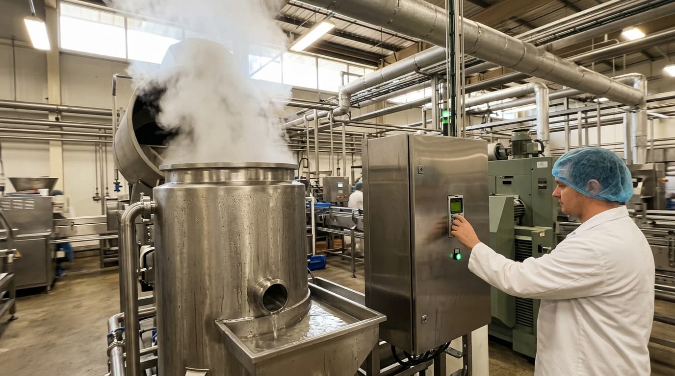
Purpose-built condensing systems for food processing, chemical plants, pharmaceutical facilities, and water treatment operations.
Advancements and Future Trends
As the industry moves toward higher computing power, several innovations are transforming how condensers are designed and applied:
- Waste Heat Recovery (District Heating): Instead of rejecting server heat to the atmosphere, modern data centre condensers are designed to run at elevated condensing temperatures (e.g., 55°C to 65°C), allowing the rejected thermal energy to be piped directly into local district heating networks for homes, offices, or agricultural greenhouses.
- Three-Phase Hybrid Cooling Loops: Integrating liquid-to-air dry coolers with direct-to-chip water loops and evaporative cooling. This combination allows operators to match cooling performance with shifting seasonal temperatures and server workloads, optimising thermodynamic efficiency dynamically.
- Smart Condensers with Predictive Maintenance: Integrating IoT vibration sensors, pressure transducers, and optical fouling sensors. These tools stream real-time operational data to machine-learning models, allowing maintenance teams to schedule cleaning sessions before performance degradation impacts PUE.
Conclusion
The design of condensers for data centre cooling applications is a multi-layered engineering challenge where thermodynamics, fluid dynamics, and environmental stewardship intersect. As server heat loads continue to rise, and global regulations on water usage and low-GWP refrigerants tighten, successful condenser design hinges on selecting the right balance of heat transfer area (A), managing internal fluid pressure drops, and applying smart control strategies. Optimising these elements ensures that digital infrastructure remains both highly reliable and environmentally sustainable for years to come.
