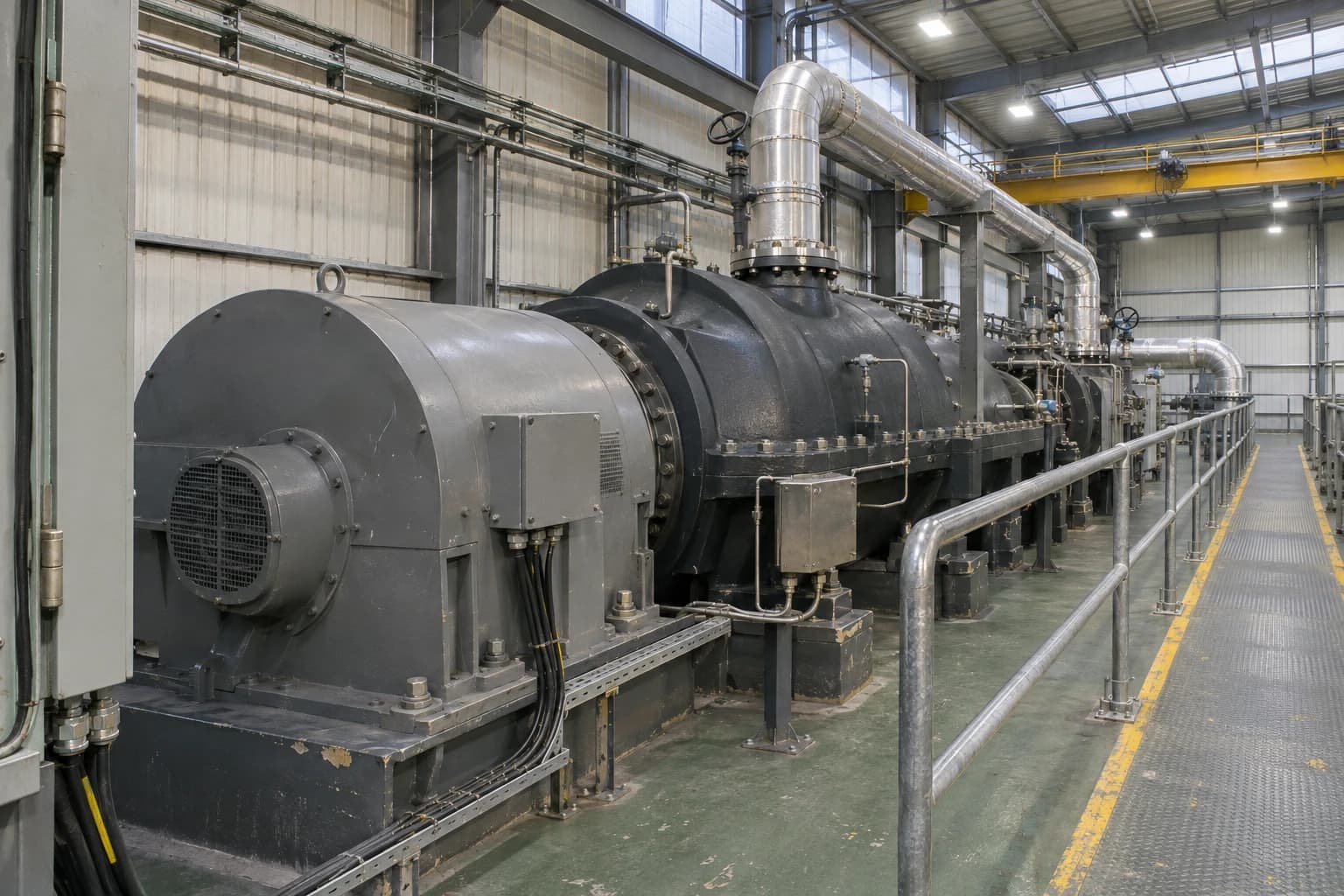
How Steam Cycle Pinch Analysis Sets Optimum Steam Headers
Grand composite curves can reveal HP steam potential and MP-to-LP substitution.
Steam cycle pinch analysis is a process-integration method that identifies the steam generation, steam demand and header pressure levels that allow an industrial site to recover the most process heat with the least fuel use.
A refinery may operate high-pressure, medium-pressure and low-pressure steam headers established through decades of expansion. A paper mill may supply dryer sections, evaporators and turbines from several pressure levels. A food factory may generate steam in a central boiler house while cooking, concentration and refrigeration processes release heat elsewhere on site.
These headers can be reliable and familiar while still being thermodynamically misaligned with current production. New consumers may have been connected to the nearest main. A heat-recovery project may generate steam at a convenient existing pressure rather than the pressure that gives the best recovery target. Steam may be throttled through pressure-reducing valves while low-pressure steam is vented or a boiler continues to cover an avoidable load.
Steam cycle pinch analysis tests the whole arrangement. It sets thermodynamic targets before a site commits to a new boiler, heat-recovery steam generator, turbine, pressure-reducing station or exchanger network.
Why steam-header pressure affects site fuel use
Steam is both a heating utility and an energy carrier
A steam header supplies heat at a pressure that corresponds to a saturation temperature. Higher-pressure steam can serve higher-temperature duties, provided the exchanger retains sufficient temperature driving force. Producing that steam also requires a higher-temperature heat source.
The pressure choice therefore affects the quantity and quality of recoverable heat. A hot process stream may contain substantial energy but lack the temperature needed to raise feedwater and evaporate it at the proposed high-pressure level. Assigning that heat to medium-pressure or low-pressure steam generation may recover more of it.
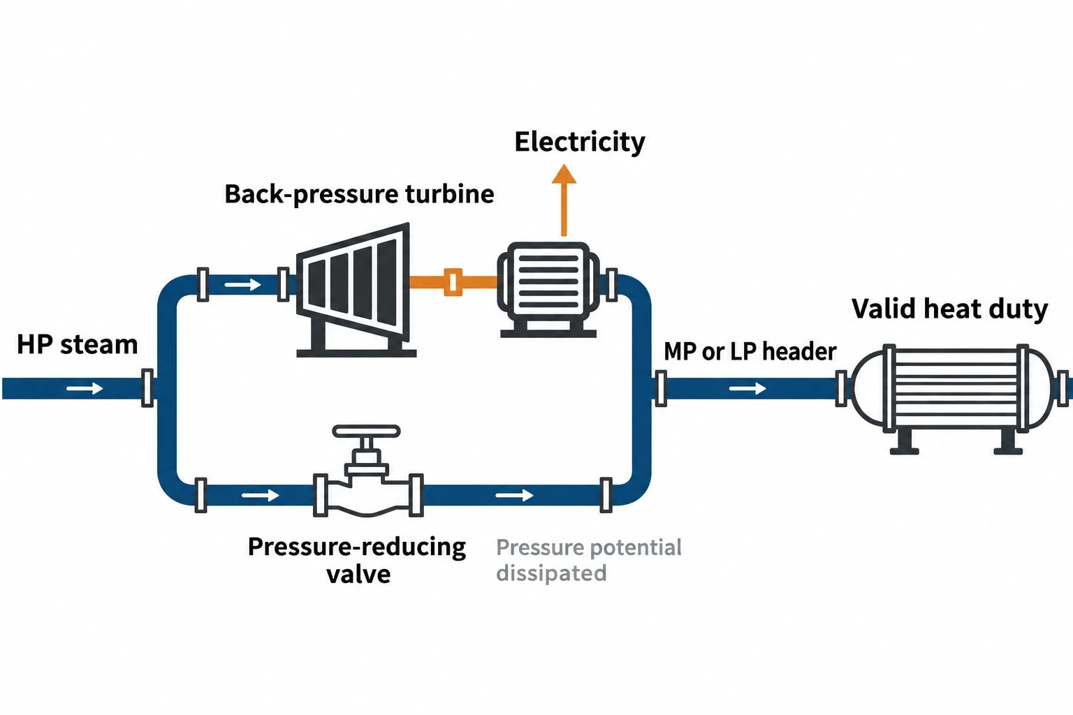
Header pressure also determines the available expansion opportunity. High-pressure steam can expand through a back-pressure turbine to provide useful medium-pressure or low-pressure steam while generating electricity. A pressure-reducing valve delivers downstream steam but dissipates the pressure potential.
Three linked questions follow:
- How much process heat can generate steam at each pressure level?
- Which consumers require high, medium or low-pressure steam?
- Where can a turbine, rather than a valve, reduce pressure while serving a valid steam demand?
A sound answer needs a site-wide heat balance. Boiler testing, steam-trap surveys and turbine performance reviews remain valuable, but they cannot independently establish the best relationship between process heat recovery and steam-header levels.
Historic header names can obscure the real requirement
Terms such as HP, MP and LP describe relative pressure levels within one site. They do not demonstrate that each pressure is necessary for every user connected to it.
A reboiler, dryer, steriliser or evaporator needs enough steam temperature to achieve its process target, plus a realistic exchanger approach temperature. The selected header must also maintain pressure during normal changes in load. These physical requirements should determine the steam level supplied to the user.
Supplying a lower-temperature duty from a higher-pressure header can create avoidable boiler firing and additional throttling. Conversely, reducing a header pressure without checking every connected duty can erode exchanger driving force, impair control or prevent a process from reaching its specified temperature.
Steam cycle pinch analysis provides the framework for separating genuine process constraints from inherited piping arrangements.

Pinch analysis identifies the thermodynamic minimum energy requirement of your process — then designs the heat exchanger network to achieve it.
How the grand composite curve guides steam cycle pinch analysis
The GCC shows heat surplus and deficit by temperature
Conventional pinch analysis starts with a stream table. Hot streams require cooling and cold streams require heating. Engineers select a minimum approach temperature that reflects exchanger type, fouling, controllability and economics, then construct composite curves and calculate minimum heating and cooling targets.
The grand composite curve, usually called the GCC, displays the site’s net heat surplus or deficit across the shifted temperature range. Instead of reviewing dozens or hundreds of individual streams, engineers can see where the process has heat available and where it needs external utility.
For steam-header work, that view is especially useful because every pressure level has a temperature requirement. The GCC indicates whether a process heat surplus can support the sensible heating, evaporation and, where applicable, superheating required for a particular steam condition.
A GCC does not prescribe equipment. It establishes what is thermodynamically feasible and where the biggest mismatches occur.
Compare the GCC with the existing steam balance
The key step is to overlay the process heat-source and heat-sink profiles with the existing steam-generation and steam-consumption profiles. The comparison reveals whether the current utility system fits the process temperature requirements.
Typical observations include:
| GCC observation | Interpretation for the steam system | Engineering question |
|---|---|---|
| A heat surplus remains above the proposed HP steam-generation level | Process heat may support further HP steam generation | Can the added HP steam displace boiler firing or expand through a turbine? |
| Surplus heat appears only at lower temperatures | HP steam generation would have a poor thermal match | Would MP or LP generation recover more useful heat? |
| MP steam consumption sits within a temperature range served by LP steam | Part of the MP demand may be over-specified | Can the user operate with LP steam and adequate exchanger driving force? |
| Large flows pass through pressure-reducing valves | Pressure potential is being dissipated | Can a turbine, revised extraction condition or different header pressure create more value? |
| LP steam is surplus while cooling remains necessary | Low-grade heat has limited process demand | Can the site identify a valid LP consumer or revise the generation target? |
The comparison can expose an important distinction. A site may have a large total heat-recovery opportunity but limited capacity to convert that heat into valuable high-pressure steam. Thermal quantity alone does not set the header pressure. Temperature quality and the destination for the resulting steam matter equally.
Setting optimum steam-header pressures from process duties
Start with the process temperature requirement
Header pressure should follow the duty at the process exchanger. Engineers need the required process-side temperature, the expected operating range and the practical minimum approach temperature. Saturated steam then provides a starting point for selecting a supply pressure.
This assessment should include the full operating envelope. A duty that appears suitable for LP steam during normal production may require MP steam during a batch heat-up, at a seasonal peak rate or after fouling has reduced exchanger performance. A header rationalisation project must distinguish between short operating peaks that need an alternative arrangement and continuous demand that sets the main header requirement.
Process users often need separate review because nominally similar equipment can have different constraints:
- Reboilers may require sufficient driving force to maintain separation performance.
- Dryers can require stable pressure and condensate removal as well as heat-transfer area.
- Sterilisers and retorts may have defined temperature and pressure cycles.
- Evaporators can be sensitive to boiling-point elevation and vapour-side pressure.
- Tank heating coils may have substantial warm-up loads but lower steady-state demand.
The optimum header arrangement emerges from the combined site requirement, rather than from the maximum pressure demanded by one consumer.
Represent the whole water-steam path
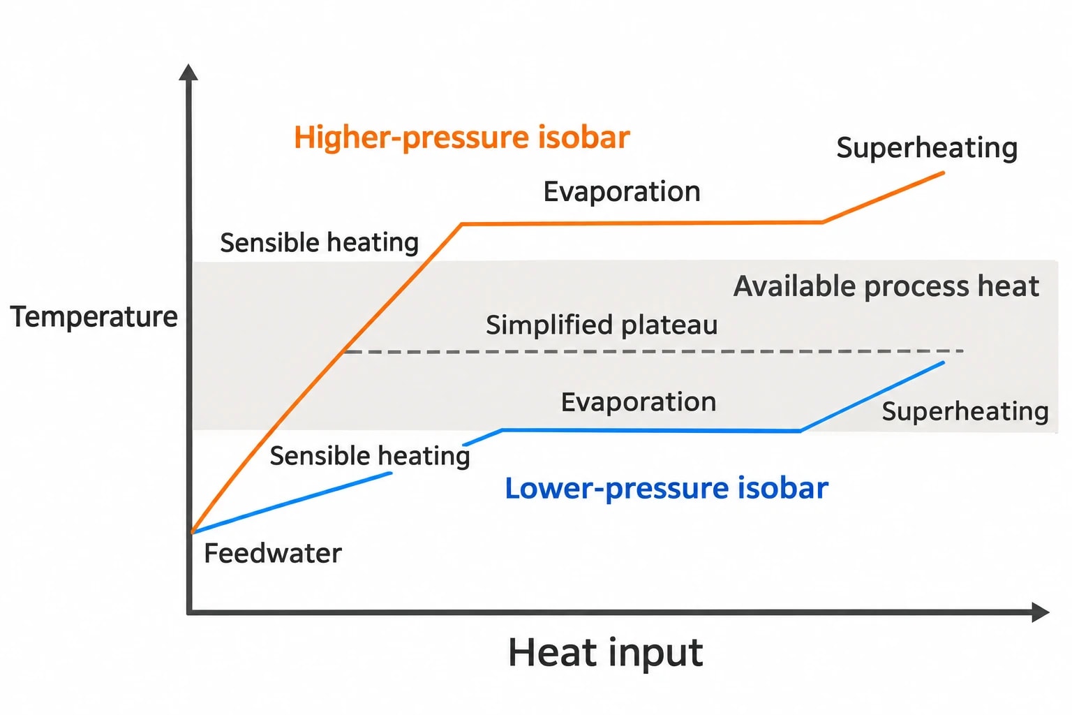
A steam level should not be represented solely as latent heat at the saturation temperature. Feedwater must be heated, water must evaporate, and many systems include superheating or reheating. These segments consume heat over a temperature range.
This point becomes more important as steam pressure rises. The sensible heat required to raise feedwater to saturation can form a larger part of the total heat input. A model based only on a horizontal evaporation plateau can overstate the potential for high-pressure steam generation from process heat.
Steam cycle pinch analysis therefore benefits from representing complete water-steam isobars in the composite curves. This gives a more realistic thermal match between available process heat and the steam cycle.
A high-pressure option may offer valuable turbine work but reject more recoverable heat because the process heat source cannot meet the feedwater-heating and evaporation temperature profile. A lower-pressure option may capture more heat but create steam with limited demand. The GCC makes this compromise visible before detailed equipment design.
Test pressure levels as a set
Each header affects the others. Increasing the HP header pressure may create a better turbine inlet condition but reduce process heat-recovery potential. Lowering an MP header may permit more heat recovery and greater HP-to-MP turbine expansion, while reducing the temperature available to connected users.
The study should test alternative pressure sets with likely flows, rather than adjusting one header in isolation. At each case, engineers can assess:
- Process heat recovered into steam generation.
- Fired boiler duty displaced.
- Steam supplied directly to process consumers.
- Flow through turbines and pressure-reducing stations.
- Surplus steam, venting and cooling duties.
- Exchanger area and practical temperature approaches.
- Header stability under credible operating cases.
The selected target balances heat recovery, electricity value where relevant, capital cost, operating flexibility and production risk.

Pinch analysis identifies the thermodynamic minimum energy requirement of your process — then designs the heat exchanger network to achieve it.
Finding HP generation and MP-to-LP substitution opportunities
Targeting additional HP steam from recovered process heat
A gap between the process heat-source profile and the existing steam-generation profile may indicate potential for additional HP steam generation. This result is a thermodynamic target. It does not establish that a heat-recovery steam generator should be installed.
The next stage assesses the quality and availability of the heat source. Engineers should investigate fouling, corrosion, contamination risk, process variability, maintenance access, feedwater quality, steam separation, control response and available plot space. Batch processes require time-dependent analysis because an attractive annual energy balance may not provide sufficiently reliable heat at a given moment.
The use of additional HP steam determines project value. It may reduce boiler fuel, increase turbine generation, release constrained boiler capacity or improve resilience during high process demand. A site that already bypasses turbines, vents LP steam or holds high boiler minimum loads needs the wider utility imbalance addressed before further steam generation can deliver its predicted benefit.
Replacing unnecessary MP demand with LP steam
The process heat-sink profile can expose the opposite opportunity. Some duties currently supplied from an MP header may operate at temperatures compatible with LP steam. Moving these users to LP steam reduces MP demand and can release high-pressure steam for turbine expansion or lower boiler output.
This substitution requires detailed process review. Product quality, hygienic requirements, control-valve authority, start-up demand, heat-transfer area, condensate pressure and normal fouling allowance all require confirmation. A move to lower-pressure steam can be attractive in pinch targets but impractical if the lower saturation temperature removes too much exchanger driving force.
Condensate arrangements deserve equal attention. A lower steam pressure changes the differential pressure available across traps and condensate-return equipment. Flash steam may also redistribute between headers. The revised system must maintain stable condensate removal at low load and during pressure disturbances.
Treat let-down stations as evidence, not an automatic defect
Pressure-reducing valves serve legitimate control and safety functions. Some provide rapid response during turbine trips, start-up or maintenance. Their presence signals a location for analysis rather than a guaranteed turbine project.
A sustained, predictable let-down flow can justify examination of a back-pressure turbine or a revised extraction arrangement. Intermittent let-down may have insufficient annual energy value to support capital investment. The GCC and the measured operating profile together determine whether pressure recovery has a credible role in the selected utility target.
A practical workflow for steam cycle pinch analysis
Build a data set that reflects real operation
A credible study boundary includes production areas, boiler plant, turbines, pressure-reducing stations, condensate returns, flash vessels and material heat-recovery equipment. Omitting a major return, vent or intermittent process load can distort the apparent header balance.
The data set should capture:
- Hot and cold process streams, including supply and target temperatures, heat-capacity flowrates, phase changes and operating hours.
- Header pressures, temperatures, flowrates and control arrangements.
- Boiler fuel consumption, feedwater condition, blowdown and turndown constraints.
- Turbine inlet, extraction and exhaust conditions across the actual operating range.
- Steam-user flow, pressure, condensate conditions and minimum process temperature requirements.
- Flash-steam generation, condensate return routes, venting and known losses.
- Production rates, batch schedules, grade changes and planned plant modifications.
Metered data needs reconciliation against process balances and field observations. A flowmeter at the boiler house shows steam leaving the source. It does not show whether the steam delivers useful heat, expands through a turbine, throttles across a valve or reaches a poorly performing condensate system.
Separate thermodynamic targets from project selection
Pinch targets define the theoretical direction of travel within the chosen constraints. Project concepts convert those targets into equipment and operating changes. Keeping these stages separate prevents a preferred technology from determining the analysis outcome.
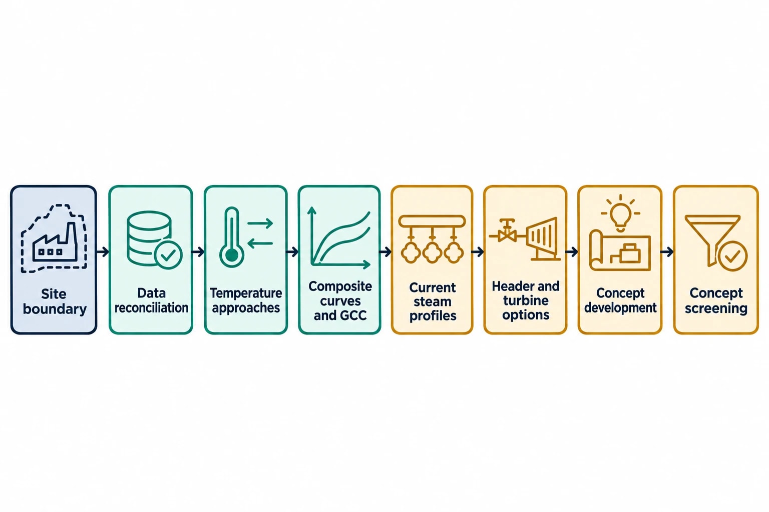
A disciplined sequence is:
- Define the site boundary and relevant operating cases.
- Reconcile steam, fuel, condensate and process data.
- Select realistic minimum temperature approaches.
- Develop composite curves and the GCC.
- Overlay the current steam-generation and consumption profiles.
- Test alternative header pressures, steam-generation targets and turbine conditions.
- Develop exchanger, steam-cycle and control concepts that approach the selected target.
- Screen concepts for economics, outages, maintainability, safety and production impact.
The strongest proposals often combine measures. A revised MP header pressure may enable extra turbine expansion, while a process exchanger generates LP steam and a targeted condensate improvement resolves a constraint in the receiving system.
Making pinch targets operable in a live steam system
Design for disturbances, start-up and turndown
Annual energy targets do not guarantee stable header operation. Steam systems experience production changes, batch transitions, trips, boiler constraints and maintenance outages. New heat recovery can reduce fired-boiler turndown margin or alter turbine extraction flows that previously stabilised a header.
Detailed design should establish header pressure-control philosophy, bypass duties, turbine-trip response, boiler minimum-load limits, condensate handling and start-up sequences. Engineers should assess normal, low-load, high-load and abnormal operating cases.
In the UK, changes to steam pipework, protective devices or operating limits also require attention under the Pressure Systems Safety Regulations 2000. Steam is a relevant fluid at any pressure under those regulations. The dutyholder must ensure that the modified system remains suitable for its intended operating conditions, with appropriate protective devices and examination arrangements.
Measure the result against an adjusted baseline
Steam cycle pinch analysis creates a defensible basis for energy monitoring after implementation. The baseline should account for production rate, product mix, ambient conditions where material, boiler operating mode and changes to site boundaries.
Useful indicators may include fuel per tonne of product, steam generation by header, turbine electricity generated per tonne of HP steam, condensate-return rate, steam venting and flow through pressure-reducing stations. Each indicator should have a defined purpose and clear measurement boundary.
ISO 50001:2018 provides an energy-management framework based on energy performance indicators and energy baselines. For a steam-header project, that discipline helps distinguish a lasting performance improvement from a temporary shift in production or weather conditions.
This article reflects the independent analysis and editorial opinion of EnerTherm Engineering. Product names, trademarks, and brands mentioned belong to their respective owners. EnerTherm Engineering is not affiliated with, endorsed by, or a licensee of any third-party software or product mentioned unless explicitly stated.

Simulation Engineer — EnerTherm Engineering
Rajesh Sekar is a Simulation Engineer at EnerTherm Engineering, specialising in computational fluid dynamics (CFD), finite element analysis (FEA), and thermal process simulation. He holds a degree from Cranfield University and brings extensive experience in simulation-based product development from the automotive, aerospace, and energy sectors.
