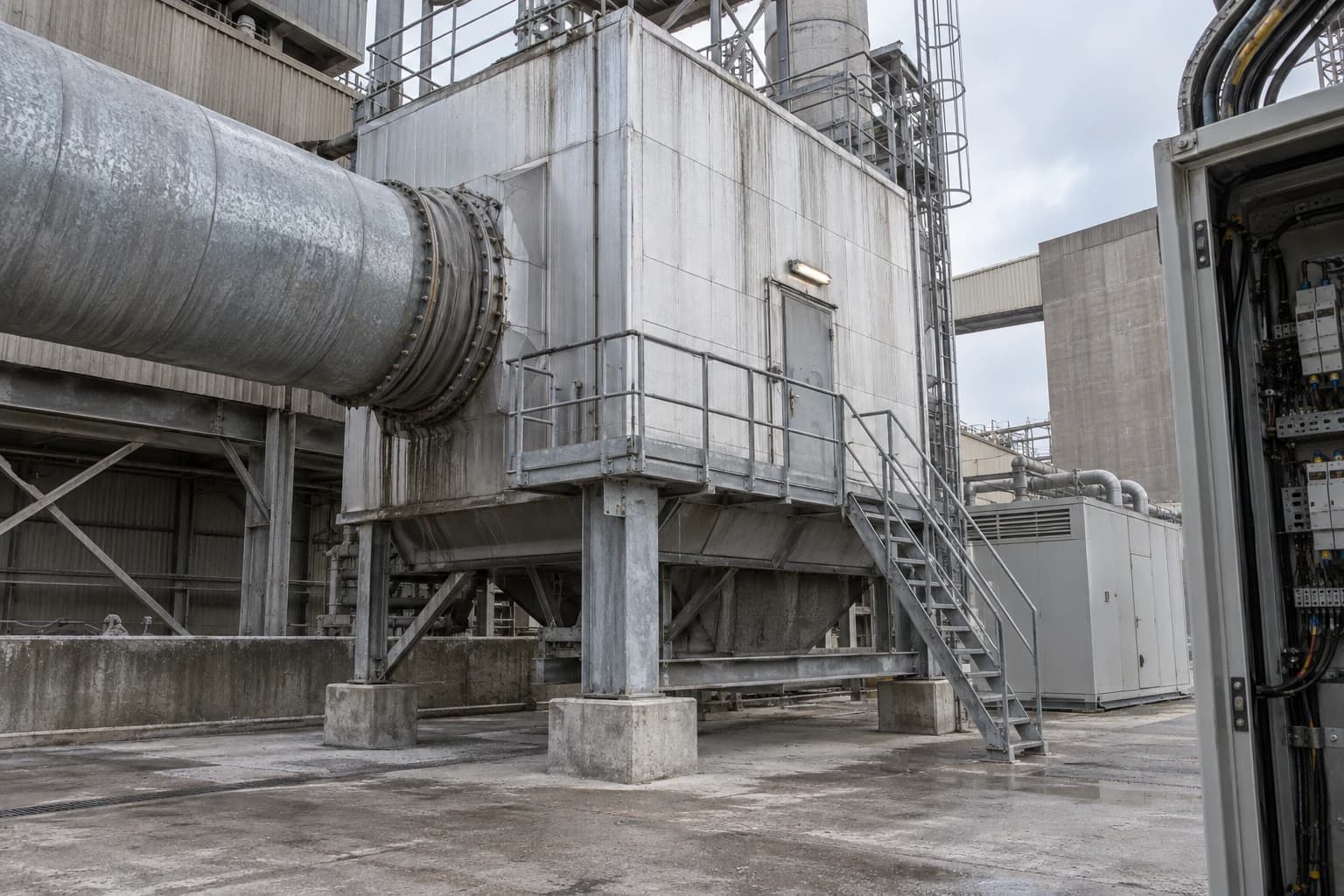
Why UK Cement Plants Can Turn Waste Heat into 4-6 MW
Cement kiln ORC systems can generate 4-6 MW on-site, offsetting up to 33% of grid power.
An industrial waste heat recovery power plant converts unused process heat into onsite electricity through heat exchangers and a power cycle, without burning additional fuel. A 5,000-tonnes-per-day clinker line can have enough recoverable heat from the preheater and clinker cooler to support around 4–6 MW of continuous electrical generation, subject to raw-material moisture, kiln configuration and operating profile.
At 5 MW, a kiln line operating continuously would produce about 120 MWh of electricity each day. Its value lies in displaced grid imports, improved supply resilience and lower electricity-related emissions.
Government research identified 48 TWh of annual industrial waste heat across eight heat-intensive sectors, equivalent to roughly one-sixth of industrial energy use. It identified 11 TWh per year of technical recovery potential across heat reuse, heat-to-power and supply to nearby industrial users. The Royal Society’s January 2026 report also placed industrial waste heat within the UK’s decarbonisation agenda, identifying cement, steel, chemicals and glass as major high-temperature sources.
For cement operators, the key question is which heat can be removed without disturbing kiln stability, raw milling, product quality or permit compliance.
Why cement kilns suit industrial waste heat recovery power plants
Cement production combines a continuous high-temperature process with large gas streams and a substantial onsite electrical load. That gives waste heat-to-power schemes a stronger technical basis than many batch-manufacturing applications.
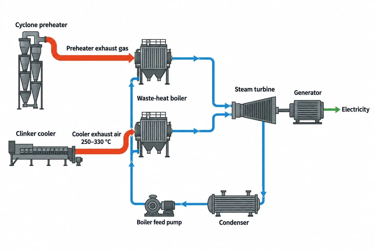
Two principal heat sources
A modern dry-process clinker line commonly has two recovery points:
- Preheater exhaust gas, after it has transferred heat to raw meal through the cyclone stages.
- Clinker cooler exhaust air, after hot clinker has discharged from the rotary kiln and passed across the cooler grate.
The clinker cooler cools clinker rapidly enough for handling, downstream grinding and product quality. Its exhaust air can remain at 250–330°C, depending on cooler configuration and heat recuperation. Preheater exhaust also carries useful energy, although its temperature, flow and availability vary with raw-mill operation and feed moisture.
The Cement, Lime and Magnesium Oxide Best Available Techniques Conclusions identify recovery from clinker cooler air and kiln flue gases as a technique operators should consider where adequate excess heat, suitable process parameters and economic viability exist.
Why the output range is credible
International Finance Corporation analysis for a typical 5,000-tonnes-per-day clinker line estimates 25–45 kWh per tonne of clinker of potential waste-heat generation. At the lower end, 25 kWh per tonne across a 5,000-tonnes-per-day line equates to about 125 MWh per day, or approximately 5.2 MW during continuous production.
The same analysis estimates a broader technical potential of 6–9 MW where both preheater and cooler heat are fully available. A UK project forecast of 4–6 MW is therefore a sensible design range when engineers allow for:
- Heat retained for raw-material drying.
- Gas-temperature variability.
- Heat-exchanger fouling margins.
- Auxiliary loads from fans, pumps and cooling equipment.
- Kiln stops, reduced-rate production and raw-mill operating modes.
- Conservative outlet-temperature limits that protect dust collection and process control.
A credible feasibility study reports net export at the generator connection, not gross turbine output.

Pinch analysis identifies the thermodynamic minimum energy requirement of your process — then designs the heat exchanger network to achieve it.
How Organic Rankine Cycle power generation works
Organic Rankine Cycle, or ORC, equipment generates electricity by vaporising an organic working fluid with recovered heat, expanding that vapour through an expander connected to a generator, then condensing and pumping the fluid around a sealed circuit.
The Energy Technology List defines ORC heat-recovery equipment as a closed thermodynamic power cycle that converts waste heat to power without internal combustion.
The role of the secondary heat-transfer loop
In a cement application, process gas should rarely pass directly into the ORC evaporator. The gas is dusty, can be corrosive and has variable flow rates. A secondary heat-transfer loop separates the process-side heat exchanger from the power module.
This arrangement normally comprises:
- A gas-to-oil or gas-to-water heat exchanger.
- A circulating heat-transfer loop.
- An ORC evaporator, expander, generator and condenser.
- A heat-rejection system, typically air-cooled or water-cooled.
- Electrical switchgear, protection and export controls.
The secondary loop protects the power module from abrasive clinker dust and allows the heat-recovery exchanger and ORC package to sit where maintenance access, noise control and cooling conditions are more favourable.
ORC versus a steam cycle
A conventional steam cycle can suit larger, hotter and relatively stable waste-heat sources. It may involve waste-heat boilers, steam drums, water treatment and a steam turbine.
ORC systems are often considered where heat is available at moderate temperatures, modularity is needed, or a packaged power island can reduce site complexity. The working fluid enables evaporation at temperatures below those required by an equivalent steam arrangement.
Neither option should be selected from gas temperature alone. Engineers must examine heat quantity, source variability, fouling risk, cooling conditions, maintenance capability, plot space and the temperature required by other process users.
Pinch analysis determines whether power is the best use of heat
Pinch analysis prevents a site from assigning high-value heat to electricity generation before testing whether it could displace more fuel or electricity elsewhere in the process.
A power plant extracts exergy from heat. Direct thermal reuse usually captures a larger share of the available energy. Cement plants can, however, have limited steady low-temperature heat demand, particularly when the kiln already supplies raw-mill drying and combustion-air duties. That can make heat-to-power more attractive than at sites with large year-round process-heating requirements.
Build the heat balance from operating data
Design teams need operating data that represents more than a nominal production day. A useful survey covers kiln operation with the raw mill running, the raw mill stopped, fuel changes, lower-output operation and planned shutdowns.
| Measurement area | Data required | Design decision affected |
|---|---|---|
| Preheater exhaust | Temperature, flow, oxygen, moisture, dust loading and pressure | Available heat and exchanger duty |
| Clinker cooler | Exhaust-air temperature, flow and cooler operating state | Recovery capacity and cooler integration |
| Raw mill | Heat demand, moisture removal and operating hours | Heat retained for drying |
| Kiln operation | Production rate, excess air, false air and stability | Seasonal and off-design performance |
| Electrical system | Import profile, demand peaks and protection arrangement | Onsite consumption and grid connection |
| Cooling system | Ambient conditions, water availability and heat rejection limits | Net ORC output in summer |
The International Finance Corporation reports that preheater and clinker-cooler gases can carry high dust loads, sometimes above 50 g/Nm³. This is a central engineering constraint. Fouling can reduce heat transfer, raise pressure drop and erode electrical output.
Protect the process pinch
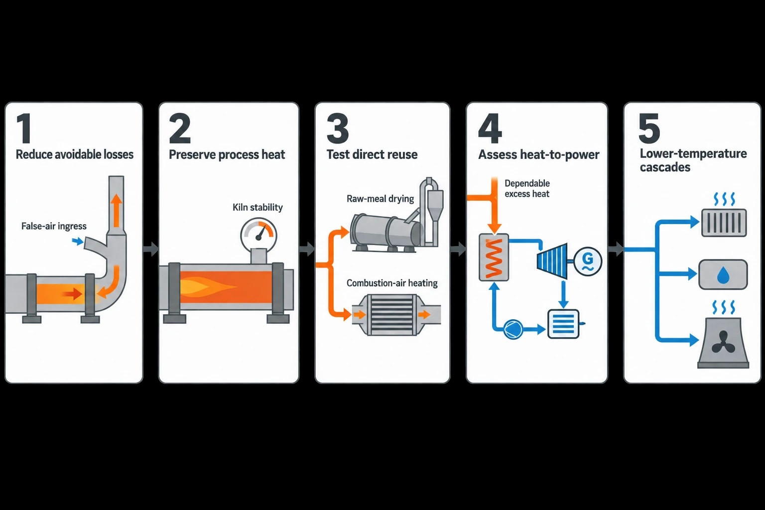
A pinch study identifies the temperature levels at which recovered heat can meet real site demand. It should assess heat recovery in this order:
- Reduce avoidable losses, including false-air ingress and uncontrolled bypassing.
- Preserve heat required for raw-meal drying, combustion-air heating and kiln stability.
- Test direct reuse opportunities within the cement process.
- Assess heat-to-power from remaining dependable excess heat.
- Consider lower-temperature heat cascades after the power cycle where suitable local demand exists.
This sequence avoids sizing a waste heat recovery power plant against gas conditions that exist only when the raw mill is off. That heat may be operationally valuable, but it does not support the annual generation profile of a continuously available source.

Pinch analysis identifies the thermodynamic minimum energy requirement of your process — then designs the heat exchanger network to achieve it.
The engineering conditions behind a dependable 4–6 MW scheme
A 4–6 MW project is a kiln-integration project with a power plant attached. The kiln and clinker cooler remain the priority equipment.
Keep the kiln stable
Heat recovery must not compromise draft control, gas conditioning, dust collection or downstream temperature limits. Additional heat exchangers introduce pressure drop, so the induced-draught fan and ductwork must be assessed with their energy use.
The design also needs operating logic for changes in kiln feed, fuel mix and raw-mill status. It may require bypass, recirculation or controlled turndown to avoid excessive process-gas cooling. These provisions preserve operating flexibility but reduce output in particular conditions.
Treat cooling as a power-generation constraint
The condenser is the cold side of the ORC cycle. High summer ambient temperatures can reduce net output from air-cooled equipment. Water-cooled systems may offer different performance characteristics but introduce water-use, treatment and permitting considerations.
The Energy Technology List distinguishes between remote secondary-cooling, integral-cooling and split-circuit ORC equipment. It sets adjusted net-efficiency thresholds by maximum waste-heat temperature and cooling arrangement. For heat sources above 350°C, the listed threshold is 22% for remote secondary-cooling units and 20% for integral or split-circuit units.
The current Energy Technology List category contains technical criteria for ORC equipment, although it reports no listed products. The criteria remain useful for comparing stated net efficiency, auxiliary consumption, test evidence and site-acceptance data.
Design for maintainability
Cement dust dictates the maintenance plan. The process-side heat exchanger needs suitable gas velocity, inspection and cleaning access, materials compatible with the flue-gas environment, and credible fouling allowances over a campaign.
Key contractual figures should include:
- Net electrical output at defined source and ambient conditions.
- Electrical consumption of all project auxiliaries.
- Minimum heat-source flow and temperature.
- Permitted process-side pressure drop.
- Availability assumptions and planned maintenance intervals.
- Guaranteed gas outlet temperatures.
- Generation during raw-mill-on and raw-mill-off operation.
These details separate a gross-output estimate from a financeable onsite-generation forecast.
UK permitting, BAT and energy management requirements
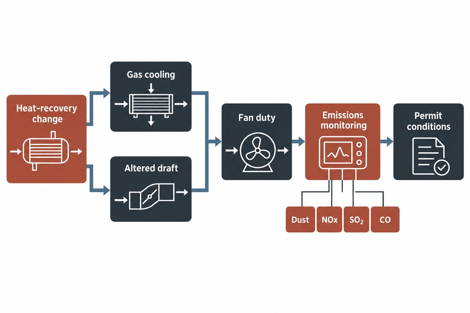
In England and Wales, cement clinker production in rotary kilns above 500 tonnes per day is a Part A(1) activity under the Environmental Permitting (England and Wales) Regulations 2016. Heat-recovery changes can affect gas paths, fan duty, emissions monitoring, cooling arrangements and operating conditions. Operators should establish early whether a permit variation or regulator engagement is required.
BAT applies to the integrated installation
The 2013 Cement, Lime and Magnesium Oxide Best Available Techniques Conclusions continue to matter for relevant UK permitting arrangements. Northern Ireland remains subject to separate applicable requirements under the Windsor Framework arrangements.
The regulator evaluates the whole installation. A power project that lowers grid imports must still maintain permit conditions for dust, nitrogen oxides, sulphur dioxide, carbon monoxide and other applicable parameters. The engineered solution must show that gas cooling, altered draft and new equipment do not weaken emissions control.
Measure performance after commissioning
ISO 50001:2018 provides an established framework for energy management. For a waste heat-to-power project, useful energy-performance indicators include net generated electricity per tonne of clinker, imported electricity per tonne of cement, heat-recovery availability and auxiliary electricity consumption.
A transparent baseline needs adjustment for clinker output, raw-material moisture, raw-mill hours and cooling conditions. Without those variables, a change in quarry moisture or production mix can be mistaken for a power-plant performance problem.
How directors should evaluate an industrial waste heat recovery power plant
The strongest projects begin with process evidence and end with a whole-life operating case.
The decision framework
Engineering directors, energy managers and sustainability leaders should require five linked assessments:
- A time-resolved heat and mass balance covering representative kiln states.
- Pinch analysis to establish the highest-value use of each heat source.
- A process-integration study covering pressure drop, gas temperatures, dust, bypass duty and raw-mill interaction.
- A net-power model that includes cooling performance and all auxiliary loads.
- A commercial case based on avoided imported electricity, maintenance costs, production availability and verified annual generation.
The commercial case should treat waste heat as variable process energy, not a uniform fuel source, and protect clinker output and environmental performance.
This article reflects the independent analysis and editorial opinion of EnerTherm Engineering. Product names, trademarks, and brands mentioned belong to their respective owners. EnerTherm Engineering is not affiliated with, endorsed by, or a licensee of any third-party software or product mentioned unless explicitly stated.

Managing Director — EnerTherm Engineering
Dr. François Pierrel is Managing Director of EnerTherm Engineering with over two decades of expertise in thermal design, heat transfer, and industrial energy optimisation. He holds a PhD in Heat Transfer from Cranfield University and a Post-Doctorate from Heriot-Watt University.
