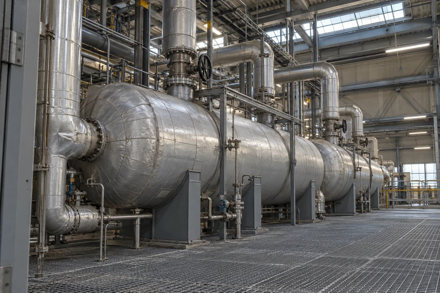
Why Feedwater Preheater Pinch Analysis Finds Heat Limits
ASME PTC 12.1 measurements pair with composite curves to test recovery limits.
Feedwater preheater pinch analysis is a process-integration method that identifies the minimum temperature driving force and external heat required to raise boiler feedwater through a heating train.
A feedwater train can contain several closed heaters, a deaerator, drains cascaded between pressure levels, an economiser and recovered process heat. Each item may appear satisfactory in isolation. The train can still consume more boiler fuel than thermodynamics requires, or direct a useful heat source to the wrong temperature level.
Pinch analysis evaluates the full set of hot streams releasing heat and cold streams demanding heat. It provides a heat-recovery target before a new exchanger, extraction line or heat-recovery scheme is specified. For a power station, refinery or steam-intensive manufacturer, it shows where a proposed feedwater preheater is constrained by temperature, flow or the existing heat-exchanger arrangement.
It also prevents a familiar error: pursuing extra recovered duty without checking whether the source has sufficient temperature quality. A large low-temperature heat source may reduce condenser or cooling duty, yet remain unable to replace high-temperature extraction steam in the final feedwater heating stages.
Why feedwater temperature affects boiler fuel use
Regenerative feedwater heating reduces boiler duty
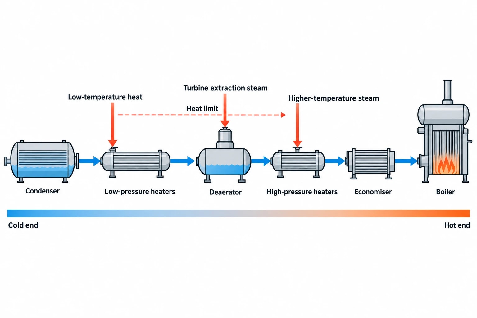
Feedwater leaves the condenser at a comparatively low temperature and must reach a temperature suitable for the economiser and boiler. Heating it with turbine extraction steam, condensate drains or recovered process heat reduces the sensible heat the boiler must supply.
This is regenerative feedwater heating. It improves the temperature match between heat addition and the water-steam cycle. Extraction steam gives up energy that could otherwise expand through later turbine stages, so the arrangement requires a balanced cycle design. The objective is not to maximise feedwater temperature at any cost. It is to identify the combination of heat recovery, extraction flows and temperature approaches that reduces total fuel use while maintaining practical turbine output, operability and equipment life.
The scale can be substantial on modern steam cycles. Some ultra-supercritical plants use ten feedwater-heating stages and achieve final feedwater temperatures of up to 300 °C. Existing industrial sites are usually constrained by turbine extraction points, installed heaters, pipework routes, fouling history and control philosophy. Pinch analysis establishes what those constraints mean in energy terms.
Feedwater heating has a temperature hierarchy
A feedwater train has several temperature levels. Low-pressure heaters recover heat from low-pressure extraction steam and drains soon after the condenser. The deaerator commonly provides an intermediate direct-contact heating stage while removing dissolved gases. High-pressure heaters then raise feedwater temperature before the economiser.
Each level needs heat at an appropriate temperature. Heat from a low-temperature source can serve the cold end of the train. It cannot lift feedwater at the hot end unless a suitable temperature difference remains across the exchanger.
That distinction creates the heat limit. A site may identify surplus heat in turbine exhaust, condensate, compressor cooling water, flue gas or process cooling circuits. Pinch analysis tests whether the heat source overlaps with feedwater demand at a feasible approach temperature. If it does not, the apparent recoverable duty is not available to that part of the train.

Pinch analysis identifies the thermodynamic minimum energy requirement of your process — then designs the heat exchanger network to achieve it.
How feedwater preheater pinch analysis works
Start with reliable stream data
The analysis begins with a defined operating case. For a power unit, this is often stable baseload operation, but part-load and seasonal cases should also be examined where they materially alter extraction pressures, condenser conditions or process heat demand.
The stream list should include:
- Feedwater and condensate sections requiring heating, with inlet temperature, target temperature, mass flow and specific heat data.
- Extraction-steam, drain and process streams that can release heat, with pressure, saturation condition, flow and available temperature range.
- Economiser inlet and outlet conditions where the study includes flue-gas heat recovery.
- Existing bypasses, recirculation flows, attemperator flows and minimum-flow arrangements that change actual duty.
- Heat losses, pressure drops and design limits that affect viable exchanger matches.
A heat balance based on one unreliable flow measurement can create a false opportunity. Meter validation, reconciled operating data and comparison against turbine heat-balance information should precede curve construction. The feedwater train should also be checked at representative load points because extraction-steam pressure and available duty change with turbine load.
Build hot and cold composite curves
Pinch analysis combines individual hot streams into a hot composite curve and cold streams into a cold composite curve. The curves plot temperature against cumulative enthalpy. Their overlap shows the potential for internal heat recovery; their separation identifies the external heat and cooling required after feasible recovery.
For a feedwater train, the cold composite curve represents the heat needed to lift condensate and feedwater through the required temperature range. The hot composite curve represents extraction steam, drains and recovered heat that can cool or condense while transferring heat.
The closest permitted approach between the curves is the pinch. It is the limiting temperature location in the overall heat-recovery problem. The pinch may sit in a low-pressure heater, around deaerator conditions, in a high-pressure heater or at the economiser boundary. It can also move when unit load changes.
A chosen minimum approach temperature has a direct commercial consequence. A smaller approach may increase theoretical heat recovery, but requires more surface area and can increase sensitivity to fouling, control instability and measurement error. A larger approach reduces capital intensity and operating risk while leaving more heat for utilities or cooling systems.
Use shifted temperatures consistently
Engineers apply the selected minimum approach temperature by shifting hot and cold stream temperatures before constructing the composite curves. This applies the required temperature driving force consistently across the feedwater train.
The temperature shift is a targeting device, not a physical change to process temperatures. It reveals whether recovered heat can meet feedwater demand while retaining the selected exchanger approach. The resulting targets show:
- Minimum external heating required for the defined case.
- Minimum cooling or heat rejection required.
- Maximum feasible heat recovery.
- The temperature region where a new match is thermodynamically possible.
- The pinch location that limits further recovery.
These targets establish the gap between current operation and the best achievable case under the assumptions used. They do not prove that every theoretical kilowatt can be installed economically or controlled safely.
What the pinch reveals in a feedwater heating train
It separates temperature limits from equipment faults
A closed feedwater heater with a poor outlet temperature may have a mechanical or operational problem. Common causes include tube fouling, tube leakage, inadequate extraction-steam flow, high level, drain-valve behaviour, gas binding, incorrect isolation status or excessive feedwater flow.
Pinch analysis answers a different question. It determines whether the proposed temperature rise is feasible once the full train and available heat sources are considered. The result distinguishes two situations that can look similar in operating data:
- A closed feedwater heater has lost performance and should achieve more duty after repair, cleaning or correction.
- The feedwater train has reached a thermodynamic heat limit because available heat is too cool, too small in quantity or required elsewhere at a higher temperature.
This distinction protects capital budgets. Enlarging a heat exchanger does not overcome an insufficient source temperature. Adding surface may reduce a local approach, but the full network may still be limited by the pinch.
It identifies cross-pinch heat transfer
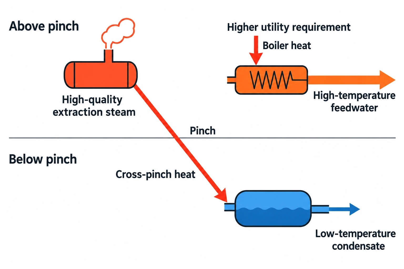
Pinch design rules discourage heat transfer across the pinch. In practical feedwater systems, a cross-pinch arrangement can occur when high-quality extraction steam heats low-temperature condensate while a higher-temperature feedwater section still needs boiler heat or a hotter extraction source.
The network may operate, yet its utility requirement rises because useful high-temperature heat is consumed below the pinch. Pinch analysis identifies this mismatch and tests alternatives such as reassigning an extraction source, recovering drain heat at a lower level, changing heater sequencing or directing a process heat source to the appropriate feedwater section.
The objective is to identify an actionable energy opportunity while preserving deaerator duty, turbine extraction conditions, condensate chemistry controls and required operating margins.
It exposes a source-temperature shortfall
Consider a refinery utility system with low-grade heat available from a cooling duty. The total available heat may appear larger than the remaining feedwater duty. A composite curve can show that the source cools below the temperature needed for the final high-pressure heater. That heat may still suit condensate preheating or boiler make-up water, but it cannot directly displace high-pressure extraction steam.
Feedwater preheater pinch analysis converts a broad statement such as “surplus heat is available” into a temperature-specific conclusion: which feedwater section can use it, how much duty can transfer, and where the heat limit remains.

Pinch analysis identifies the thermodynamic minimum energy requirement of your process — then designs the heat exchanger network to achieve it.
Pair pinch targets with closed feedwater heater diagnostics
Terminal temperature difference indicates the hot-end approach
ASME PTC 12.1 defines terminal temperature difference, or TTD, as the difference between the saturation temperature corresponding to the steam inlet pressure and the feedwater outlet temperature. It is the key operational measure of a closed feedwater heater’s hot-end temperature approach.
A rising TTD relative to the corrected design condition can indicate reduced heat-transfer performance or changed operating conditions. The cause requires investigation. A high TTD can result from fouling, air accumulation, incorrect steam pressure, flow imbalance, inadequate surface area for the current condition, or errors in temperature and pressure measurements.
For pinch analysis, TTD provides a practical equipment constraint. A composite-curve target based on an approach smaller than the heater can reliably sustain will overstate recoverable heat. Conversely, a corrected performance test may show that a heater is operating well above its achievable approach, revealing recoverable duty without changing the network arrangement.
Drain-cooler approach tests cold-end recovery
ASME PTC 12.1 defines drain-cooler approach, or DCA, as the drain outlet temperature minus the feedwater inlet temperature. It describes the cold-end relationship between cascade drains and entering feedwater.
DCA matters because drain cooling can supply low-temperature duty that reduces extraction-steam demand or condenser loading. A larger-than-expected DCA may identify unclaimed recoverable heat. The conclusion must be checked against drain level, subcooling requirements, flashing risk in downstream drain systems, corrosion considerations and the heater design.
TTD and DCA should be compared against corrected design expectations, not treated as fixed universal values. Feedwater flow, extraction pressure, heater level, condenser pressure and load all alter the measured result.
| Measurement | What it indicates | Pinch-analysis use |
|---|---|---|
| TTD | Hot-end temperature approach in a closed feedwater heater | Sets a realistic upper-temperature approach constraint |
| DCA | Cold-end relationship between drain outlet and feedwater inlet | Tests available low-temperature drain heat recovery |
| Feedwater pressure drop | Tube-side hydraulic cost of added duty or altered routing | Checks whether a proposed match creates unacceptable pumping demand |
| Extraction-steam pressure and flow | Temperature and quantity of heating steam | Defines the hot-stream duty available at each temperature level |
| Heater level and drain-valve position | Drainage and control condition | Helps separate performance loss from unstable operation |
Where practical feedwater heat-recovery constraints arise
Turbine and steam-cycle constraints
Extraction steam is part of the turbine-cycle design. A new or increased extraction demand can affect turbine power output, internal pressures, gland sealing conditions and operating limits. Available extraction conditions can vary significantly with load, particularly on units operating flexibly to support variable generation.
A pinch target should therefore be assessed with the steam-cycle heat balance. The final scheme may require several cases: full load, normal dispatch, minimum stable load, summer cooling-water conditions and expected process-steam demand. A match that performs well at baseload may have limited value during the hours when fuel cost or carbon exposure is greatest.
Existing plant configuration
Commission Implementing Decision (EU) 2017/1442 identifies feedwater preheating using recovered heat as a best available technique for large combustion plants. BAT 12(h) describes preheating water leaving the steam condenser with recovered heat before reuse in the boiler. Its applicability is limited to steam circuits, and existing units can face constraints from plant configuration and the amount of recoverable heat.
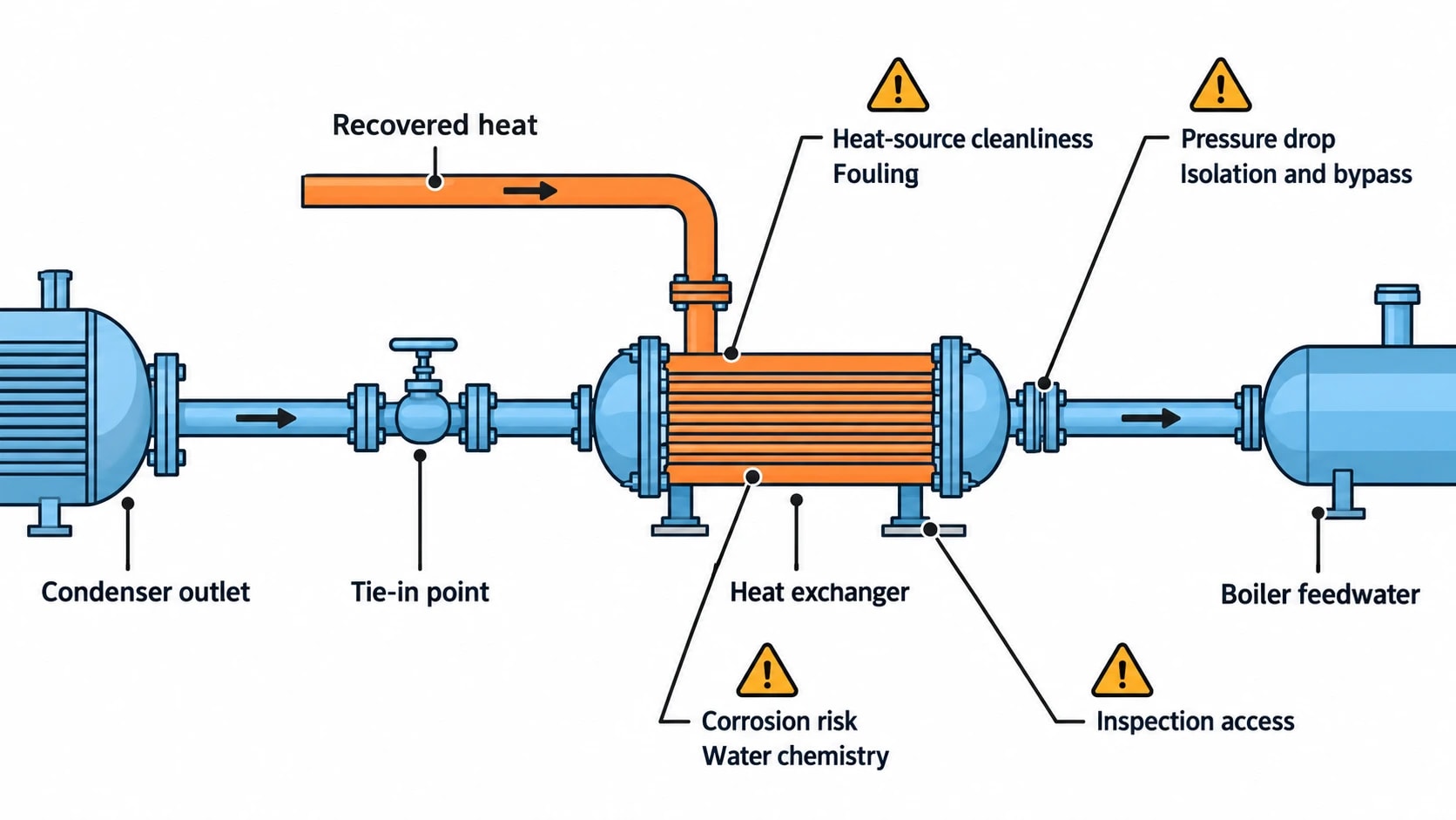
Those limits are physical, not administrative. Pipework may lack an accessible tie-in point. A heat source may be intermittent. A new exchanger may impose an unacceptable pressure drop. Available space, lifting access, water chemistry segregation, start-up thermal stress and protection logic can determine whether a pinch target becomes a viable project.
For UK sites, retained pre-2021 EU BAT Conclusions remain relevant to permit assessments. The Environmental Permitting (England and Wales) Regulations 2016 define a large combustion plant as one with a total rated thermal input of 50 MW or more. Site permit requirements and regulator guidance remain the decisive compliance reference.
Fouling, corrosion and availability
Recovered heat is valuable only when the heat exchanger remains available and maintainable. Low-temperature flue-gas recovery can introduce acid-dew-point and corrosion risks. Process-side recovery may present fouling, cross-contamination or cleaning challenges. Feedwater and condensate circuits also require strict chemistry control.
A technically sound study includes:
- Heat-source cleanliness and expected fouling rate.
- Feedwater chemistry and contamination consequences.
- Materials selection for the expected temperature and corrosion environment.
- Isolation, bypass and drainage arrangements.
- Start-up, shutdown and low-load thermal-stress limits.
- Inspection access and outage requirements.
- Control response during rapid changes in turbine load or process demand.
These considerations determine the economic minimum approach temperature and configuration suitable for the site.
A disciplined workflow for feedwater preheater pinch analysis
Establish the operating cases and data basis
Define the equipment boundary and select operating cases before gathering data. Reconcile measured temperatures, pressures and flows against known heat balances. Record the uncertainty attached to each value, particularly for low differential-temperature duties.
Then define which streams are eligible for recovery. Include only heat that is genuinely available after meeting safety, process and operational obligations.
Target the heat limit before designing equipment
Construct composite curves for each important operating case and identify the pinch, minimum utility targets and feasible recovery at selected approach temperatures. Test sensitivity to extraction pressure, feedwater flow, condenser temperature and assumed fouling allowance.
Rank opportunities by energy value, temperature compatibility and installation feasibility. Typical outcomes include restoring underperforming closed feedwater heaters, recovering drain heat more effectively, adding low-temperature condensate preheat, revising heater allocation or rejecting a proposal that lacks adequate temperature driving force.
Convert targets into an operable project
The final stage is heat-exchanger-network design. It checks pressure drops, exchanger area, controllability, isolation philosophy, bypass requirements, water chemistry, maintenance access and economics. Turbine-cycle modelling confirms the effect on output and fuel use.
Pinch analysis distinguishes a repairable heater problem, a poor temperature match and a genuine heat limit set by the steam cycle, giving engineers a basis for performance restoration, a new heat-recovery match or a different efficiency measure.
This article reflects the independent analysis and editorial opinion of EnerTherm Engineering. Product names, trademarks, and brands mentioned belong to their respective owners. EnerTherm Engineering is not affiliated with, endorsed by, or a licensee of any third-party software or product mentioned unless explicitly stated.

Simulation Engineer — EnerTherm Engineering
Rajesh Sekar is a Simulation Engineer at EnerTherm Engineering, specialising in computational fluid dynamics (CFD), finite element analysis (FEA), and thermal process simulation. He holds a degree from Cranfield University and brings extensive experience in simulation-based product development from the automotive, aerospace, and energy sectors.
