How Refinery Pinch Analysis Finds Heat Recovery in CDUs
EU refinery BAT conclusions identify pinch analysis for heat integration and recovery
Refinery pinch analysis is a thermodynamic method that sets minimum heating and cooling targets, then identifies where process streams can exchange heat to meet them. In a crude distillation unit, it examines the crude preheat train as one connected thermal system rather than a sequence of individual exchangers.
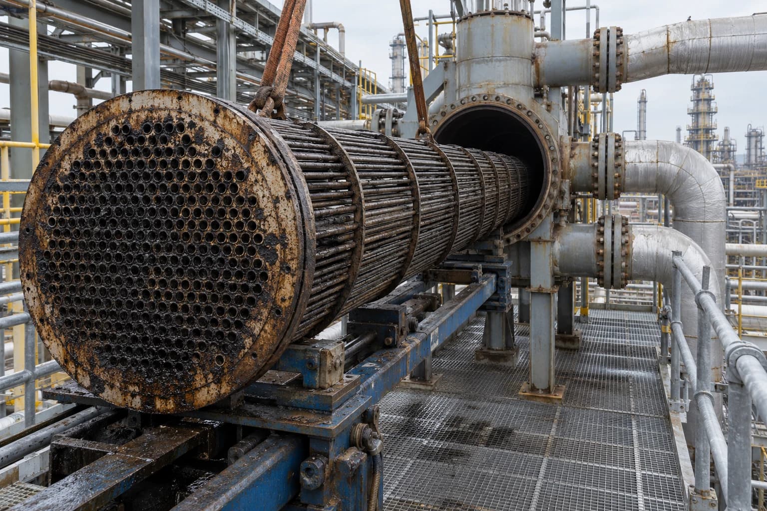
A CDU raises desalted crude temperature substantially before it reaches the fired heater and atmospheric column. Product rundown streams, pumparounds, reflux circuits and atmospheric residue all contain recoverable heat. The preheat train transfers much of it to incoming crude, but exchanger matches often reflect years of incremental modifications, changing crude slates and maintenance interventions.
The JRC Refining BREF identifies the CDU preheat train as a direct application for pinch analysis. Its recommendation is specific: increase crude preheat temperature while minimising heat rejected to air and cooling water. The engineering is more complex. A viable project must respect exchanger fouling, pressure drop, column operation, desalter performance and changing crude properties.
Why refinery pinch analysis focuses on the CDU preheat train
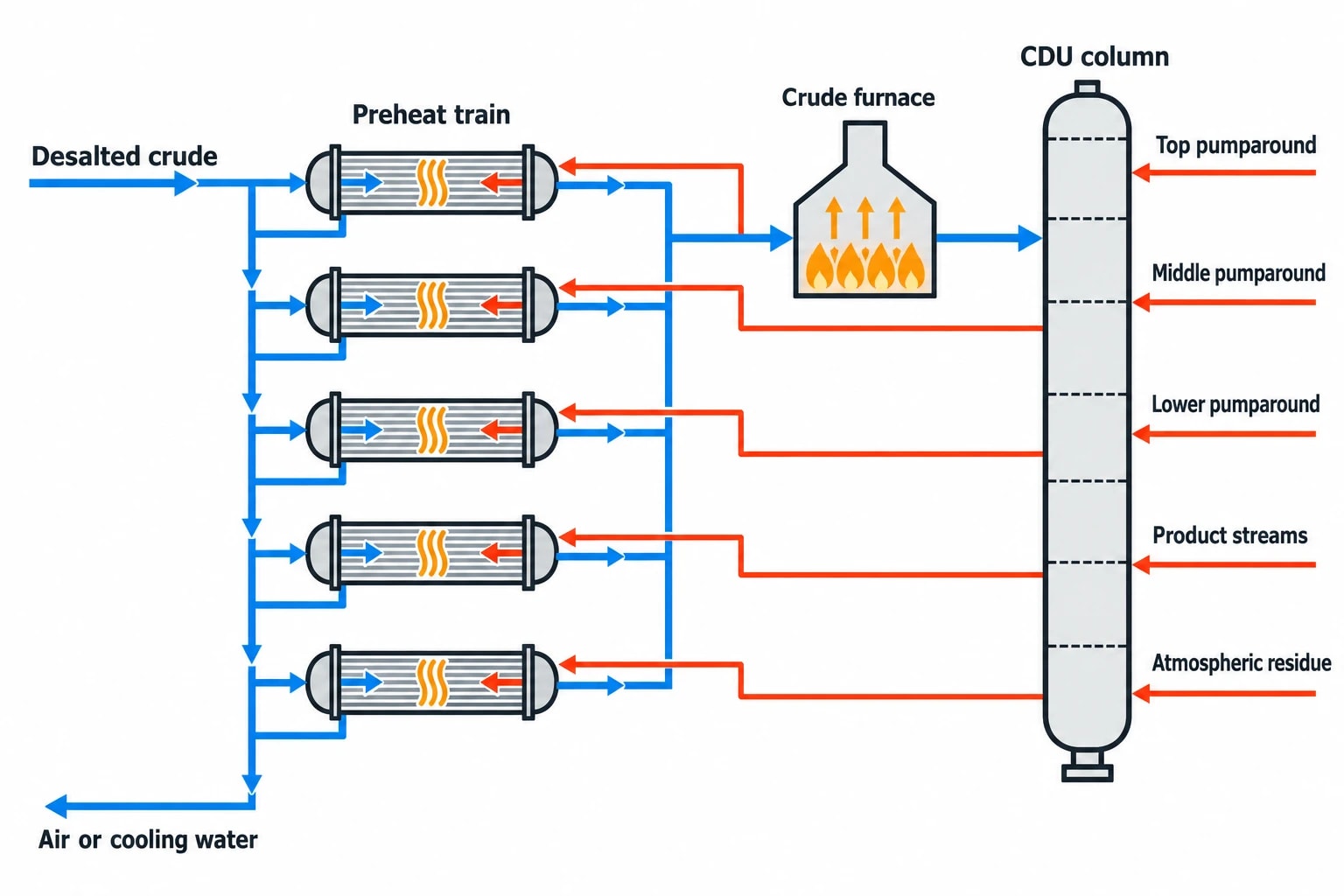
A crude distillation unit separates crude oil into fractions across a boiling range. These include refinery gas, naphtha, kerosene, gas oils and atmospheric residue. Before separation, crude passes through the preheat train and crude furnace.
The preheat train recovers heat from process streams that require cooling. It can include exchangers connected to:
- Top, middle and lower pumparounds
- Overhead and side-product streams
- Atmospheric residue
- Product rundown streams
- Reflux and circulating streams
- Selected streams from adjacent refinery units
Each exchanger may perform adequately in isolation. That does not prove the train makes the best use of available heat. A low temperature approach in one exchanger can force cooling elsewhere, while a wider approach can be acceptable if it preserves a higher-value heat match later in the network.
The furnace duty exposes the heat-recovery gap
The crude furnace supplies the heat the preheat train cannot recover. Increasing crude temperature at furnace inlet therefore reduces furnace duty, provided the revised train does not introduce operational limits.
Pinch analysis quantifies process heat available at useful temperature levels and separates it from heat that is too cold, unavailable during normal operation or impractical to recover.
The result is more useful than a list of underperforming exchangers. It shows whether the limitation is insufficient exchanger area, unsuitable stream matching, cross-pinch heat transfer, excessive cooling below the pinch or fouling.
Define the study boundary before analysing the network
The starting boundary is usually the CDU preheat train. It should include desalted crude as the principal cold stream, hot product and pumparound streams, the furnace as hot utility, and air or cooling-water systems as cold utility.
A broader boundary may include the vacuum distillation unit where operating schedules, plot layout and stream availability support integration. The JRC Refining BREF notes that modern CDU heat integration can extend to high-vacuum units and, in some cases, thermal crackers.
Interunit integration requires more than a favourable temperature match. A heat source that disappears during an adjacent-unit turnaround can constrain CDU operation. Teams should distinguish between heat that is continuously available, conditionally available and unsuitable for normal operation.

Pinch analysis identifies the thermodynamic minimum energy requirement of your process — then designs the heat exchanger network to achieve it.
How refinery pinch analysis sets CDU heat-recovery targets
Pinch analysis starts with process data, not an exchanger proposal. Engineers build a stream table describing each hot and cold stream across the selected operating cases.
For each stream, the analysis needs supply temperature, target temperature, mass flow, heat-capacity flowrate, phase behaviour, pressure constraints and operating availability. Utility supply and return conditions also need definition.
Build a defensible CDU stream data set
Plant data from a CDU deserve close scrutiny. Throughput changes, crude assays vary, pumparound circulation rates move, and exchanger fouling develops between turnarounds. A process-flow diagram may show the intended network, while historian data show the network in operation.
A sound validation stage compares historian values with process simulation and reconciled mass and energy balances. Engineers should investigate unexplained differences before targeting heat recovery. A temperature-transmitter error, unrecorded bypass or assumed exchanger duty can create a false opportunity.
| Data item | Purpose in refinery pinch analysis |
|---|---|
| Stream supply and target temperatures | Defines the usable temperature range for heat exchange |
| Mass flow and heat capacity | Establishes heat duty and temperature change |
| Phase change | Prevents incorrect treatment of condensing or vapourising streams |
| Crude blend and throughput | Tests the opportunity across the expected operating envelope |
| Fouling condition | Separates design performance from current recoverable duty |
| Pressure-drop allowance | Prevents a heat-recovery project from creating a hydraulic limit |
| Product specifications | Protects cut points, product quality and downstream feed conditions |
| Utility temperatures | Determines whether process heat can replace fuel or cooling duty |
One operating case can identify potential. An investment-quality study should assess normal throughput, high throughput, a difficult crude blend and an end-of-run fouling case. A project that succeeds only with one light crude and freshly cleaned exchangers has limited operational value.
Select a practical minimum temperature approach
The minimum temperature approach, usually written as ΔTmin, defines the closest practical temperature difference between hot and cold streams. It has a major effect on the heat-recovery target.
A smaller ΔTmin produces a more ambitious utility target, but may require more exchanger surface, tighter control and less tolerance for fouling. A larger ΔTmin reduces surface requirements but leaves more duty for the furnace and cooling systems.
There is no single correct refinery ΔTmin. The selected value should reflect exchanger type, crude viscosity, fouling behaviour, pressure level, control requirements, available plot space and project economics. A condensing stream may justify a different approach from a crude-to-product sensible heat exchanger.
The objective is an attainable end-of-run target, not the lowest theoretical furnace duty.
Composite curves show where CDU heat recovery is constrained
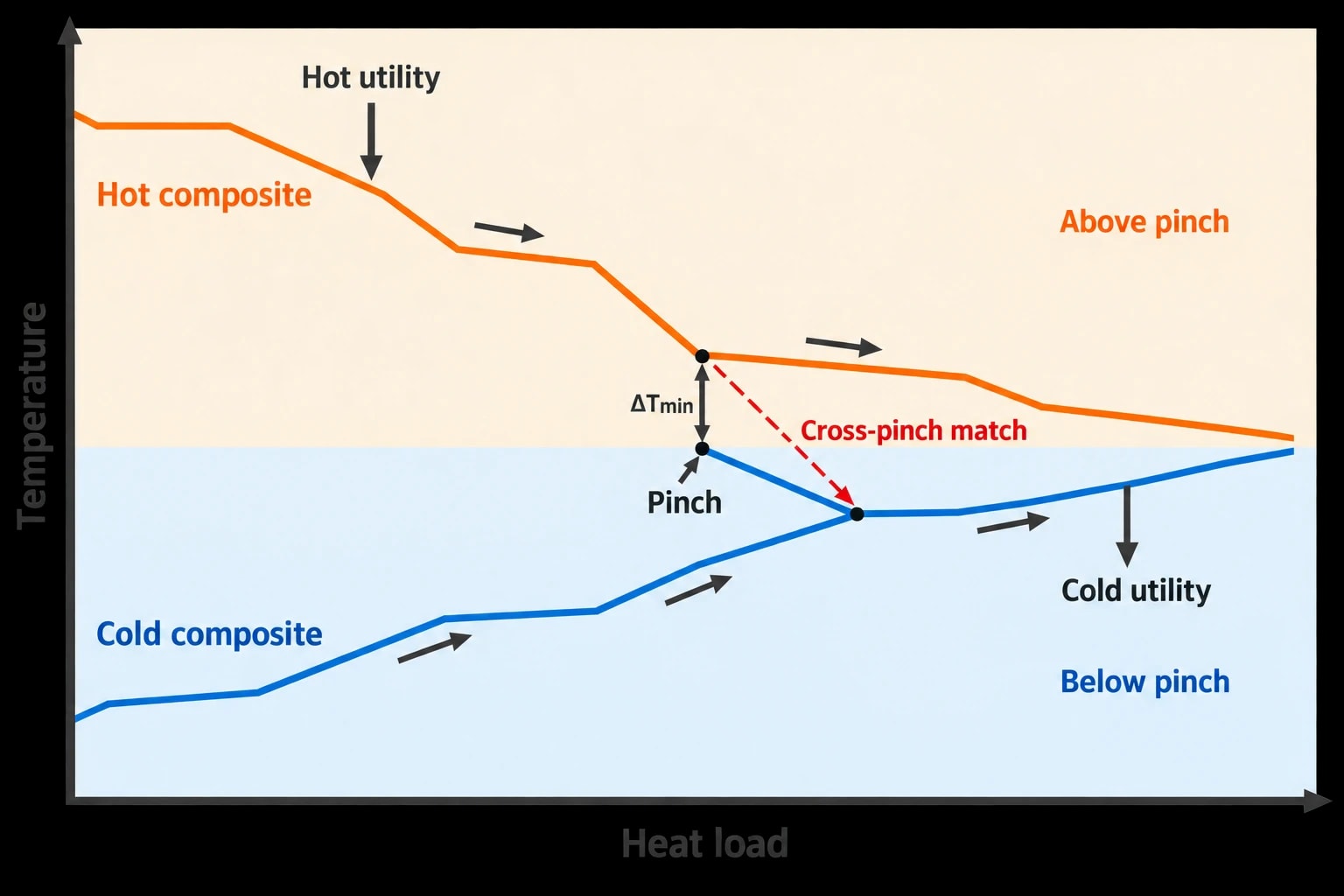
After stream data have been adjusted for ΔTmin, composite curves combine hot and cold process streams by temperature and heat load. They show the heat available from streams requiring cooling and the heat required by streams needing heating.
The closest point between the curves is the pinch. It is the region where the process has the least freedom to transfer heat.
What the pinch means in a crude preheat train
Above the pinch, high-temperature process heat should serve cold streams that need high temperatures. Below the pinch, engineers should minimise heat rejection to air coolers and cooling water where another cold process stream can absorb it.
Three established pinch rules guide the target:
- Do not transfer process heat across the pinch.
- Do not use external hot utility below the pinch.
- Do not use external cold utility above the pinch.
These rules identify utility penalties in the thermodynamic target. They do not override operating safeguards. A CDU may retain cooler duty for product-temperature control, furnace margin for start-up, or a bypass to protect desalter conditions.
A cross-pinch match deserves particular attention during a retrofit review. It transfers heat from above the pinch to below it, increasing both hot and cold utility demand relative to the target. Removing the match can be attractive, but only after checking whether it performs a necessary control, hydraulic or product-temperature function.
The grand composite curve identifies the type of opportunity
The grand composite curve presents the process heat surplus or deficit at each temperature level. It helps process integration teams distinguish between heat that can reduce furnace duty and heat that only shifts a cooling load.
For CDUs, common opportunities include:
- Raising crude preheat with heat currently rejected to air or cooling water
- Reallocating existing exchanger duty to improve temperature matching
- Recovering pumparound duty at a more useful temperature level
- Enlarging an existing exchanger where the stream match remains valid
- Adding a crude-to-product exchanger below the pinch
- Linking a CDU and vacuum-unit stream where both units provide reliable availability
A grand composite curve does not specify the pipe route or exchanger geometry. It establishes where the thermal opportunity sits, avoiding premature equipment selection.

Pinch analysis identifies the thermodynamic minimum energy requirement of your process — then designs the heat exchanger network to achieve it.
Turning refinery pinch analysis into CDU retrofit options
The utility target is the start of the retrofit process. Engineers must convert it into a workable exchanger-network modification with acceptable pressure drop, controllability, cleaning access and maintenance requirements.
Audit the existing exchanger network
A field audit should map all operating exchangers, bypasses, spare units, parallel trains and recent modifications. Drawings may not capture a temporary operating line-up that became routine.
For each exchanger, the audit should compare current performance with design and clean expectations:
- Heat duty and terminal temperature differences
- Overall heat-transfer coefficient
- Tube-side and shell-side pressure drop
- Fouling history and cleaning interval
- Bypass position and control-valve behaviour
- Mechanical condition and remaining life
- Expected performance at crude-rate changes
This identifies whether the heat-recovery problem lies in the network structure or individual exchanger degradation. Both can occur at the same time.
Common CDU retrofit routes
| Retrofit route | Potential heat-recovery benefit | Engineering checks |
|---|---|---|
| Reassign an existing exchanger | Improves temperature matching with limited new equipment | Stream suitability, piping changes and control interaction |
| Add surface area to an existing match | Raises duty where the current pairing remains appropriate | Pressure drop, fouling allowance and maintenance access |
| Add a crude-to-product exchanger | Recovers heat previously rejected to cooling | Product temperature, corrosion and cleaning method |
| Split a stream | Improves network flexibility and temperature matching | Flow control, maldistribution and turndown behaviour |
| Revise pumparound heat recovery | Uses column heat at a different temperature level | Column hydraulics, draw conditions and product specifications |
| Integrate with a vacuum-unit stream | Extends recovery beyond the CDU boundary | Unit availability, turnaround planning and process safety review |
The benefit of extending the study boundary can be material. In a 2017 Applied Thermal Engineering study, Chengtian Cui and Jinsheng Sun analysed three industrial CDU preheat trains and proposed interunit coupling with inner-unit optimisation. Their simulated design reported an additional 9.58% reduction in energy consumption. The result is case-specific, but shows why a CDU-only boundary can hide valid heat matches.
The authors retained the basic structure of the individual trains and pursued limited revamping. Refinery retrofit work rarely begins with a blank sheet. Existing exchangers, pipe racks, access routes and turnaround windows influence the preferred design.
Fouling changes the refinery pinch analysis result
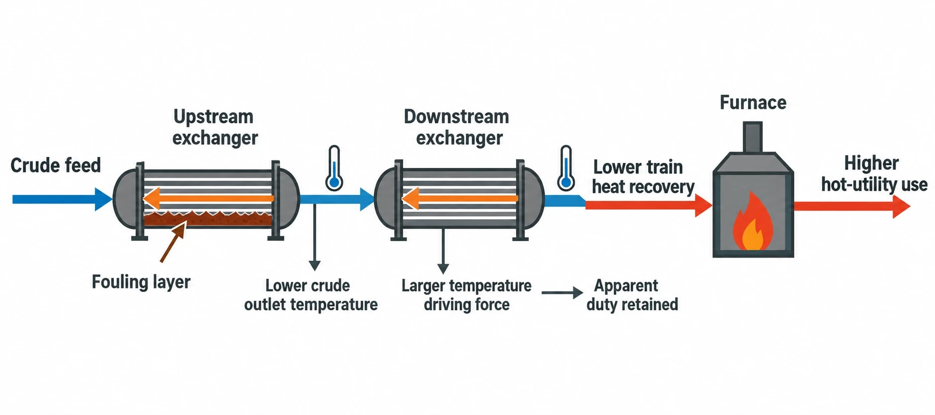
Fouling changes the thermal behaviour of a crude preheat train over time. It lowers overall heat-transfer coefficients, reduces exchanger duty and can increase pressure drop. A target based only on clean exchanger performance risks overstating recoverable heat.
The effect can be counterintuitive. Fouling in an upstream exchanger can lower crude outlet temperature. A downstream exchanger may then retain apparent duty because colder crude creates a larger temperature driving force. The downstream exchanger can look healthy while the train has lost heat recovery overall.
Measured fouling effects in a refinery case study
A 2021 Chemical Engineering Transactions study by Nurul I. M. Yusoff and co-authors examined fouled CDU and condensate-fractionation preheat trains. The authors identified eleven severely fouled exchangers. Four showed large duty reductions from their design duties, while the remaining exchangers retained duty partly because upstream fouling created higher downstream temperature differences.
For the fouled light- and heavy-crude cases, current hot-utility consumption was 41% and 47% above the pinch targets respectively. The study linked the shortfall to lower process-to-process heat recovery, lower furnace inlet temperature and greater heat rejection to cooling water and air coolers.
The authors modelled retrofit options that added or enlarged exchangers below the pinch, combined with more frequent attention to exchangers at the higher-temperature end of the train. Their proposed options indicated a 7% to 10% reduction in fuel-gas consumption, depending on the crude scenario.
Those figures should not become a generic refinery benchmark. They show why fouling must appear in operating cases, rather than as an afterthought once a pinch target has been set.
Treat fouling as a design constraint
A preheat-train retrofit should test expected duty at the end of the run cycle. The review should include crude properties, wall temperatures, velocity, pressure drop, exchanger geometry and cleaning feasibility.
Higher velocity can reduce deposit growth in some services, while reduced wall temperature can lower fouling tendency. Both changes may affect pressure drop, pumping demand and mechanical suitability. Process engineers need to assess those trade-offs alongside the heat-recovery target.
A practical refinery pinch analysis workflow for CDUs
A structured workflow moves the study from data collection to an investable scope.
1. Set the operating cases and battery limits
Define whether the study covers the CDU alone or includes credible links to the vacuum unit. Set throughput, crude blends, product targets, utility conditions and turnaround assumptions.
2. Reconcile plant data and confirm the line-up
Compare historian values with process simulation, laboratory data and exchanger datasheets. Confirm active bypasses and exchanger configuration in the field.
3. Develop pinch targets for each case
Calculate hot and cold utility targets and identify the pinch location for realistic ΔTmin values. Report ranges where crude slate or fouling materially affects the result.
4. Generate exchanger-network concepts
Identify exchanger reassignment, new area, stream splits, revised pumparound recovery and interunit options. Screen each concept against pressure drop, control needs and plot constraints.
5. Test operability before ranking projects
Model desalter conditions, furnace inlet temperature, flash-zone behaviour, column hydraulics, product specifications, start-up and turndown. Include fouling progression and cleaning requirements.
6. Develop the project basis
The selected option should include heat and material balances, exchanger datasheets, piping scope, control changes, isolation philosophy, maintenance access and a performance-measurement plan. That basis turns refinery pinch analysis from a heat target into a CDU retrofit that can sustain its duty between turnarounds.
This article reflects the independent analysis and editorial opinion of EnerTherm Engineering. Product names, trademarks, and brands mentioned belong to their respective owners. EnerTherm Engineering is not affiliated with, endorsed by, or a licensee of any third-party software or product mentioned unless explicitly stated.

Managing Director — EnerTherm Engineering
Dr. François Pierrel is Managing Director of EnerTherm Engineering with over two decades of expertise in thermal design, heat transfer, and industrial energy optimisation. He holds a PhD in Heat Transfer from Cranfield University and a Post-Doctorate from Heriot-Watt University.
