Refinery Pinch Analysis Tests Heat Recovery Before FEED
Composite curves set utility targets; fouling can cut heat duty by up to 23%.
Refinery pinch analysis is a process-integration method that sets thermodynamic targets for heat recovery and minimum utility demand across refinery process streams before equipment is specified. It gives a refinery team an early answer to a costly question: how much fired-heater fuel can process heat realistically displace once the existing heat-exchanger network is considered as a whole?
That answer matters most before Front End Engineering Design. A proposed exchanger match may look attractive on a process flow diagram, yet fail after pressure drop, exchanger area, crude flexibility, fouling, plot space and control requirements are tested. Refinery pinch analysis identifies the maximum recoverable heat first, then provides a framework for selecting an operable heat-exchanger-network retrofit.
The method has regulatory relevance as well as commercial value. Commission Implementing Decision 2014/738/EU identifies pinch analysis and heat integration under BAT 2 for energy efficiency in mineral oil and gas refining. Refineries need a defensible route from measured process conditions to lower fuel consumption, lower cooling duty and reduced combustion emissions.
Why refinery pinch analysis belongs before FEED
The crude distillation unit is usually the first place to examine. Cold crude requires substantial heating before entering the charge heater and atmospheric column. Meanwhile, hot products, pumparounds and side draws require cooling. The crude preheat train connects those duties through a dense heat-exchanger network.
A refinery pinch study tests whether the train uses available heat at the most valuable temperature levels. It does not treat each exchanger as an isolated asset. It considers competition between hot and cold streams throughout the network.
A process engineer may identify an apparently useful diesel-to-crude match. Pinch analysis tests whether that diesel heat should instead serve another cold stream, whether the match damages heat recovery elsewhere, and whether the revised network increases or decreases total fired-heater demand.
BAT 2 links pinch analysis with refinery energy efficiency
Commission Implementing Decision 2014/738/EU defines pinch analysis as a systematic calculation of thermodynamic targets for minimising process energy consumption. It places the technique alongside heat integration, heat and power recovery, combustion optimisation, steam management and energy benchmarking.
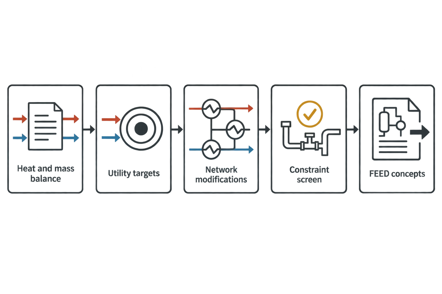
For a crude-unit revamp, the engineering sequence should be clear:
- Reconcile a representative heat and mass balance.
- Set utility and heat-recovery targets.
- Identify network modifications that could approach those targets.
- Screen each modification against mechanical, operational and economic constraints.
- Carry selected concepts into FEED.
This sequence prevents existing pipework or an early equipment arrangement from setting the energy target by default. Brownfield restrictions remain decisive, but they should shape the selected retrofit after the heat-recovery opportunity has been measured.
A whole-network target prevents local optimisation
A preheat train can include dozens of exchangers in series and parallel. Raising crude temperature at one location may lower cooler duty locally, but also remove a heat source needed elsewhere. A local improvement can therefore move utility demand around the refinery rather than reduce it.
Refinery pinch analysis establishes targets for:
- Minimum hot utility, including fired-heater fuel, imported steam or other external heat.
- Minimum cold utility, including air cooling, cooling water and refrigeration where relevant.
- Maximum feasible process-to-process heat recovery.
- Temperature levels where external utility remains unavoidable.
- Existing cross-pinch heat transfer that increases both heating and cooling demand.
The result identifies whether the refinery has a network problem, an exchanger-performance problem, or both.

Map every energy and material flow in your process with detailed heat and mass balance calculations — the foundation for any optimisation or design project.
Building the heat and mass balance for refinery pinch analysis
A pinch target is only as reliable as the stream data behind it. Refinery historian data often includes changing throughput, crude-blend shifts, bypass operation, fouled exchangers and uncertain flow measurements. The study should begin with a reconciled heat and mass balance that represents an identified operating condition.
Set a decision-focused study boundary
The study boundary should match the investment decision. A narrow crude-preheat study may begin downstream of the desalter and end at the charge-heater inlet. A wider study may include atmospheric and vacuum-column pumparounds, product cooling, stripping steam and selected utility interactions.
The boundary affects the apparent opportunity. Excluding a hot stream because it sits in a different process area can overstate charge-heater demand. Including a stream that cannot be connected because of contamination, hydraulic separation or operating risk creates an unachievable target.
The basis of design should record:
- Included process units and utility systems.
- Battery-limit temperatures and pressures.
- Existing and permitted exchanger connections.
- Design throughput and operating cases.
- Crude blends and assay basis.
- Assumptions on bypasses, standby equipment and future operating changes.
Define streams by enthalpy, not temperature alone
Each selected stream needs supply temperature, target temperature, mass flow, pressure, phase condition and enthalpy data. Specific heat can be sufficient for a limited sensible-heat range, but refinery streams often need a more detailed enthalpy-temperature relationship.
Crude, mixed hydrocarbon products and hydrogen-rich streams can show significant property changes across the relevant temperature range. Condensation, vaporisation and boiling duties require particular care. Treating those streams as constant-specific-heat services can distort the composite curves and misplace the pinch.
| Stream-data item | Relevance to refinery pinch analysis |
|---|---|
| Supply and target temperatures | Defines the usable temperature range |
| Mass flow and enthalpy | Determines stream duty and heat-capacity behaviour |
| Pressure and phase condition | Identifies flashing, condensation and hydraulic constraints |
| Crude assay or blend case | Captures changing properties and fouling exposure |
| Exchanger terminal temperatures | Confirms present network performance |
| Differential pressure | Sets hydraulic limits for new area, rerouting or increased velocity |
| Cleaning history and fouling allowance | Tests whether savings survive the operating run length |
Use several operating cases
A network designed around one favourable operating snapshot can perform badly after a crude change or throughput reduction. The study should normally test maximum throughput, normal operation, turndown, summer cooling conditions and credible crude-blend cases.
Different cases can govern different decisions. Maximum throughput may determine allowable pressure drop. A heavy crude case may determine fouling allowance and heater margin. Turndown may reveal poor temperature control, unstable exchanger bypassing or overheated product.
FEED should inherit the selected cases as formal design conditions. That makes the pinch study traceable to exchanger sizing, piping hydraulics, control design and charge-heater assessment.
How composite curves set refinery heat-recovery targets
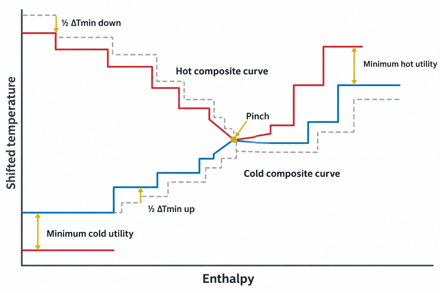
Composite curves combine the temperature-enthalpy behaviour of all relevant hot and cold streams. The hot composite curve represents process heat released as hot streams cool. The cold composite curve represents heat required as cold streams warm.
Engineers shift both curves by half the selected minimum temperature approach, ΔTmin. The closest approach between the shifted curves identifies the pinch. The separation at the high-temperature end indicates minimum hot utility. The separation at the low-temperature end indicates minimum cold utility.
ΔTmin is a retrofit decision, not a default input
A smaller ΔTmin permits more calculated heat recovery. It also requires more exchanger surface, tighter temperature approaches and closer attention to fouling, control and mechanical design. A larger ΔTmin reduces required area but increases fired-heater and cooling duties.
Refinery teams should compare several ΔTmin cases rather than selecting a generic value. The preferred value depends on:
- Stream phase and expected heat-transfer coefficients.
- Existing exchanger area and potential for added surface.
- Fouling tendency, cleaning access and target run length.
- Allowable pressure drop on crude, product and pumparound circuits.
- Utility temperatures and charge-heater operating margin.
- Capital cost, outage duration and fuel-cost basis.
This comparison exposes the point at which extra exchanger area no longer produces an attractive reduction in utility demand.
The grand composite curve places utilities at useful temperatures
The grand composite curve shows the net heat surplus or deficit at each temperature level. It helps engineers distinguish high-grade heat that can displace charge-heater firing from lower-grade heat that can only reduce cooling demand or serve a lower-temperature duty.
A megawatt of recovered heat near 80°C cannot replace a megawatt of duty required near the charge-heater inlet. Composite and grand composite curves value heat according to both quantity and temperature.

Map every energy and material flow in your process with detailed heat and mass balance calculations — the foundation for any optimisation or design project.
Refinery heat-exchanger-network retrofit screening
A pinch target is the start of retrofit design, not the final network. Existing refineries contain fixed pipe routes, exchanger shells, layout restrictions, established operating procedures and turnaround constraints. The selected heat-exchanger-network concept must work within those boundaries.
Apply pinch rules before selecting exchanger matches
Classical pinch rules remain valuable for identifying wasteful heat transfer:
- Avoid external cooling above the pinch where process heat can meet a cold-stream duty.
- Avoid external heating below the pinch where process heat can meet the duty.
- Avoid cross-pinch heat transfer unless a detailed network analysis demonstrates a wider operational benefit.
A cross-pinch exchanger match increases hot and cold utility demand against the minimum-energy target. Existing networks can contain such matches because of phased projects, plot restrictions, previous crude slates or equipment availability. The study should quantify their impact before recommending removal or rematching.
Quantify the screen for each retrofit option
A credible refinery pinch study gives each proposed match a numerical screen. The following measures allow engineering and project teams to compare options consistently.
| Decision measure | What the screen should establish |
|---|---|
| Duty recovery | Recovered process heat at each operating case, expressed against the pinch target |
| Charge-heater impact | Change in coil inlet temperature, fired duty and available heater margin |
| Exchanger area | Existing area, required clean area and required fouled area using stated overall heat-transfer-coefficient assumptions |
| Pressure drop | Predicted exchanger and piping pressure drop against the allowable limit for each stream |
| Fouling performance | Expected duty and pressure loss at the defined run length, plus cleaning strategy |
| Temperature approach | Clean and fouled terminal temperature differences at normal operation and turndown |
| Outage basis | Tie-in duration, isolation requirements, scaffold access, lifting needs and associated production exposure |
| Cost basis | Installed cost, outage cost, fuel and carbon assumptions, maintenance cost and sensitivity range |
These measures turn a theoretical match into an investment comparison. A new exchanger can offer large duty recovery yet fail because it absorbs the available crude-side pressure-drop margin. A lower-duty modification may be preferable if it can be installed during a short shutdown, uses accessible tie-ins and preserves charge-heater margin during fouled operation.
Test mechanical and operating constraints early
Potential retrofit routes include exchanger repiping, additional surface in series, bundle replacement, stream splitting, revised pumparound allocation and removal of permanent bypasses. Each proposal requires more than a temperature match.
The FEED screen should examine tube-side velocity, vibration exposure, shell-side distribution, metallurgy, inspection access, isolation, drains, vents and relief implications. It should also assess how the new match behaves during start-up, turndown and exchanger bypassing.
The refinery BAT reference document notes that deeper heat integration can increase sensitivity to unstable conditions originating in an individual unit. Control requirements therefore belong in the concept-selection stage. A heat-recovery scheme that restricts crude-temperature control or creates unstable pumparound operation can erode the expected fuel reduction.
Fouling must shape the refinery pinch target
Fouling changes both thermal and hydraulic performance. Deposits reduce the overall heat-transfer coefficient, increase pressure drop and lower crude temperature at the charge-heater inlet. The heater then supplies the missing duty.
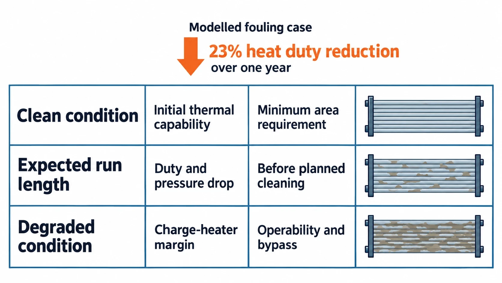
A 2025 peer-reviewed review of crude-refinery heat exchangers summarised a model of crude fouling in a refinery preheat-train shell-and-tube exchanger. The model projected a 23% reduction in heat duty over one year, alongside higher pressure drop. The review presents this as a modelled fouling case rather than a universal field result, and it does not specify a crude slate. It should therefore inform sensitivity analysis, not become a blanket design allowance.
Evaluate clean, operating and degraded conditions
A practical pinch study should assess at least three exchanger conditions:
| Condition | Design purpose |
|---|---|
| Clean condition | Establishes initial thermal capability and minimum area requirement |
| Expected run length | Tests duty and pressure drop before planned cleaning |
| Degraded condition | Confirms charge-heater margin, operability and bypass requirements during adverse fouling |
This approach links the pinch target to run length and maintenance strategy. It also prevents FEED from basing charge-heater savings solely on clean exchanger performance.
What FEED needs from refinery pinch analysis
FEED requires a selected and operable concept, not only composite curves or a theoretical utility target. The pinch study should provide a clear engineering handover.
Produce a traceable FEED package
The package should include a validated process flow diagram with stream tables, a reconciled energy balance, defined operating cases, the selected ΔTmin, utility targets, proposed network modifications and the assumptions used to screen them.
For each selected exchanger modification, FEED should establish:
- Required duty at all defined operating cases.
- Design and operating temperatures and pressures.
- Allowable pressure drop and hydraulic margin.
- Clean and fouled overall heat-transfer-coefficient assumptions.
- Required exchanger surface area and thermal design margins.
- Fouling allowance, cleaning method and expected run length.
- Materials of construction and corrosion considerations.
- Tie-in points, outage scope and construction sequence.
- Bypass, isolation, drainage, venting and control requirements.
- Charge-heater duty reduction and retained firing margin.
Convert the thermodynamic target into an investment decision
Refinery pinch analysis measures the thermodynamic prize before capital is committed. Its value depends on reconciling that prize with exchanger performance, crude flexibility, pressure drop, controllability, maintenance and outage constraints.
A validated heat and mass balance, representative operating cases and quantified retrofit screens provide a defensible route to lower fired-heater fuel use. FEED can then focus on heat-exchanger-network changes that should perform through fouling cycles, changing crude slates and normal refinery operating demands.
This article reflects the independent analysis and editorial opinion of EnerTherm Engineering. Product names, trademarks, and brands mentioned belong to their respective owners. EnerTherm Engineering is not affiliated with, endorsed by, or a licensee of any third-party software or product mentioned unless explicitly stated.

Managing Director — EnerTherm Engineering
Dr. François Pierrel is Managing Director of EnerTherm Engineering with over two decades of expertise in thermal design, heat transfer, and industrial energy optimisation. He holds a PhD in Heat Transfer from Cranfield University and a Post-Doctorate from Heriot-Watt University.
