Why Flare Gas Recovery Design Starts with Normal Loads
API 521 sizes recovery for frequent flare loads while preserving an emergency flare path.
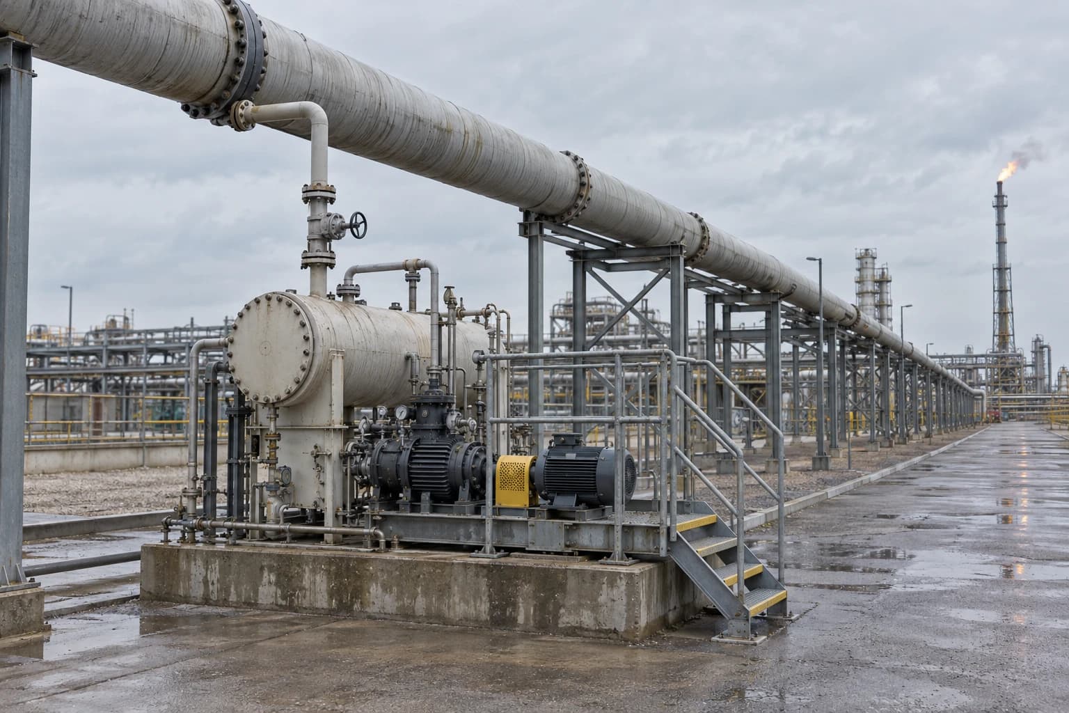
A flare gas recovery system captures routine flare-header gas, compresses and conditions it where required, and returns it to fuel gas or another suitable process destination while preserving an unrestricted emergency route to the flare.
A refinery flare system must still accept sudden relief loads during a plant upset. That safety duty shapes every recovery project. API Standard 521, seventh edition with Errata 1, states that flare gas recovery systems are seldom sized for emergency flare loads. Economics and safe operability usually favour capacity for a normal or frequently occurring flare rate, with larger events passing directly to the flare.
That distinction makes flare gas recovery design a heat and mass balance problem. The design basis must identify what reaches the flare header during stable operation, transitions, unit swings and recurring minor releases. A single average flow is not enough, nor is an emergency relief case. The recovery package needs a defensible operating envelope that captures valuable gas without raising flare-header pressure, compromising relief disposal or destabilising the refinery fuel-gas system.

Map every energy and material flow in your process with detailed heat and mass balance calculations — the foundation for any optimisation or design project.
What Does “Normal Load” Mean in Flare Gas Recovery System Design?
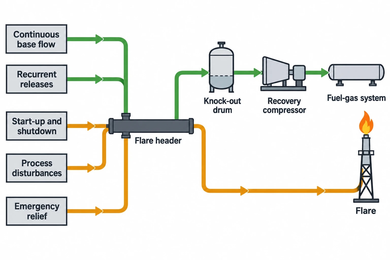
Normal load is the routine and frequently recurring gas flow entering a flare header during ordinary refinery operation. It can include continuous purge losses, small pressure-control releases, compressor seal leakage, recurring unit pressure swings and operational releases associated with known process conditions.
It does not mean the maximum possible flare load.
Routine Releases Create the Recovery Opportunity
Routine flare flow can be low in volumetric terms but significant over a year. It commonly contains fuel-value hydrocarbons, hydrogen and inert gases in changing proportions. Recovered mass depends on flow and composition, while usable energy depends on gas heating value and the receiving fuel-gas specification.
A refinery team should separate flare events into operating classes before choosing recovery capacity:
- Continuous or near-continuous base flow
- Recurrent operational releases during normal unit control
- Start-up and shutdown releases
- Short-duration process disturbances
- Emergency depressuring and major relief events
The first two classes normally define the recovery opportunity. The remaining classes test the flare system’s emergency disposal function and the recovery system’s ability to unload, recycle, isolate or bypass promptly.
The Frequently Occurring Maximum Matters More Than a Simple Average
An annual average can conceal the flow behaviour that determines compressor selection. A header with a modest mean flow may experience frequent peaks well above that mean, followed by periods close to zero. A compressor sized only to the mean can spend much of its operating life at an unsuitable point. A package sized to the highest recorded emergency flow would be expensive, poorly loaded and still unable to replace emergency flare capacity.
API Standard 521 describes the normal rate as an average flare load or a frequently encountered maximum load. The design decision requires the site’s operating record, not a generic percentage of flare capacity.
The practical objective is to recover the greatest feasible share of routine gas while allowing the flare to receive any load beyond the recovery system’s range without delay.
Build the Heat and Mass Balance from Measured Flare Behaviour
Flare gas recovery design begins with an evidence-based balance around the flare-header network, knockout equipment, recovery package and fuel-gas destination. The balance should represent time-dependent operation as well as a reconciled steady state.
Establish a Representative Data Set
Historical trends should cover enough operating conditions to include crude changes, seasonal conditions, maintenance periods, known unit constraints, start-ups and shutdowns. High-resolution data are valuable because short flare surges can disappear within hourly or daily averages.
For each operating period, engineers should reconcile:
- Flare-header pressure and pressure variation
- Flare gas flow, including measurement range and uncertainty
- Gas composition and molecular weight
- Lower heating value or refinery-specific fuel-value measure
- Temperature and pressure at the recovery compressor suction
- Liquid carryover and knockout-drum level behaviour
- Purge-gas rate
- Steam, air or gas-assist rate at the flare
- Fuel-gas header pressure, composition and demand
- Recovery compressor recycle, loading and unloading behaviour
The Refining BREF describes continuous monitoring of gas sent to flare and associated combustion parameters, including gas-mixture flow and heat content, assistance ratio, exit velocity, purge-gas flow and pollutant emissions. These measurements support flaring records and define the conditions a recovery system must accommodate.
Treat Composition as a Design Variable
Flare composition can change sharply between units and operating modes. Hydrogen, methane, C₂ to C₅ hydrocarbons, nitrogen, carbon dioxide, hydrogen sulphide, water vapour and entrained liquid each affect recovery design differently.
Hydrogen can increase volumetric flow while contributing relatively little energy per unit volume compared with hydrocarbon-rich gas. Nitrogen and carbon dioxide dilute fuel value. Hydrogen sulphide can require treatment and alter the suitability of recovered gas for a fuel-gas header. Liquid hydrocarbon carryover threatens compressor integrity and can create unstable suction conditions.
A mass balance that treats flare gas as a fixed methane-rich stream may overstate recoverable fuel value and receiving-system capacity. Component tracking should be detailed enough to assess fuel-gas quality, treating duty, liquid formation and emissions reporting.
Reconcile the Fuel-Gas Balance at the Same Time
Recovered flare gas has value only if the refinery can accept it. The receiving fuel-gas network must have sufficient demand, pressure margin and tolerance for the expected composition range.
This creates a coupled balance:
- Routine flare gas enters the recovery package.
- Compression, liquid separation and treatment alter pressure, temperature and composition.
- Recovered gas enters fuel gas or another approved destination.
- The receiving network displaces purchased or internally produced fuel where demand permits.
- Excess gas returns to the flare route if the destination cannot accept it.
A feasibility model should test low fuel demand as carefully as high flare flow. A recovery compressor may perform well while the fuel-gas system approaches pressure or quality limits. The value case then depends on controls, storage where appropriate, alternative destinations or a lower recovery set point.

Map every energy and material flow in your process with detailed heat and mass balance calculations — the foundation for any optimisation or design project.
Size Recovery Capacity Around the Operating Envelope
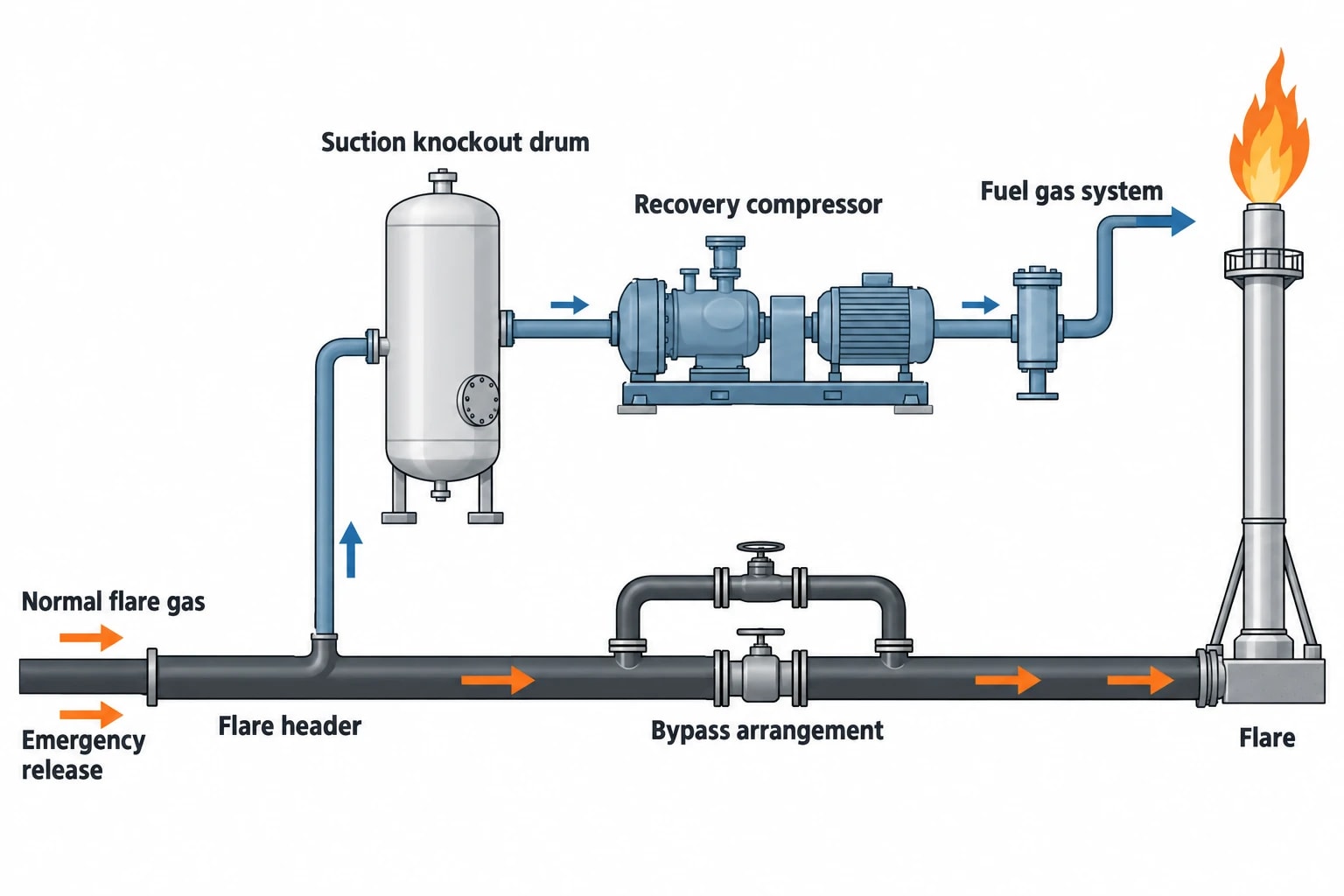
The recovery compressor and its controls should cover a realistic span of normal flare loads, rather than one design point. Available range matters as much as nominal capacity.
Use a Load Distribution, Not a Single Number
A flare flow-duration curve shows how long the system spends at each flow range. It allows engineers to compare candidate capacities against expected capture, compressor turndown, energy use and bypass frequency.
The design basis should report at least:
| Design question | Evidence required |
|---|---|
| What flow is continuous? | Minimum stable flow and duration |
| What flow recurs frequently? | Time series and event classification |
| What causes peaks? | Unit, operating mode and duration |
| What flow exceeds recovery capacity? | Expected bypass frequency and volume |
| What gas can enter fuel gas? | Composition, pressure and demand constraints |
| What remains an emergency case? | Relief-system hydraulic and safeguarding basis |
Selecting recovery capacity from a percentile alone can mislead. The right threshold depends on event duration, compressor turndown, liquid risk, receiving-system capacity and the value of additional captured gas. A short, frequent peak may justify added capacity. A longer but rare event may justify controlled bypass.
Select Equipment for Gas and Liquid Reality
Liquid-ring compressors are an established option for variable flare gas and potential liquid ingress. Other compressor arrangements can suit the gas composition, turndown requirement, suction pressure and liquid-handling safeguards. Equipment selection follows the operating envelope.
API Standard 521 notes that flare gas recovery systems operate over wide ranges and usually within narrow suction-pressure bands. Compressor recycle control, staged loading or unloading, and protection against liquid carryover are therefore central design features.
The suction knockout drum deserves the same attention as the compressor. Its sizing, level instrumentation, high-level response and liquid disposal route determine whether the package can tolerate flare-header conditions. A heat and mass balance should quantify expected condensed hydrocarbon and water phases across the range of suction temperatures and pressures.
Keep the Emergency Path Independent
A recovery system must not restrict relief disposal. During a major release, the recovery package should move out of the flare’s safety path through the approved control and bypass arrangement.
This requirement affects:
- Header pressure-control philosophy
- Bypass capacity and valve response
- Compressor trip and recycle logic
- Flare-header hydraulic assessment
- Isolation philosophy
- Response to loss of power, instrument air or cooling
- Interface between recovery controls and relief-system safeguards
The design review must demonstrate that an emergency load reaches the flare without dependence on recovery-compressor availability. Recovery is an operating improvement; the flare remains the final safety disposal route.
Why Dynamic Modelling Changes the Design Decision
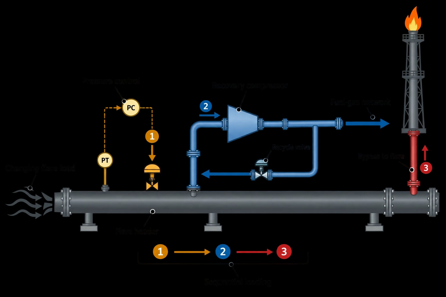
A steady-state model establishes composition, phase behaviour, fuel value and utility requirements. Dynamic modelling tests whether controls keep header pressure within the required band as flare load changes.
Test Real Operating Sequences
Dynamic cases should include normal fluctuations, loss of a recovery compressor, sudden reduction in fuel-gas demand, liquid-level excursions, start-up, shutdown and transition from routine recovery to emergency flaring.
These cases expose interactions that a steady-state design may miss. A recycle valve may maintain suction pressure during a modest flow change but reach its travel limit during a recurring unit release. Sequential compressor loading may then arrive too late, causing a bypass event. Conversely, aggressive loading can send unstable gas composition to the fuel-gas network.
The model needs actual control set points, equipment response times and valid pressure-drop relationships for the flare-header system. It should also use realistic gas-property methods for hydrogen-rich and hydrocarbon-rich mixtures. The deliverable is a tested operating philosophy with defined control limits.
Link Flare Recovery to Emissions Reporting
Commission Implementing Decision (EU) 2014/738 identifies flaring as a safety or non-routine activity under BAT 55. BAT 56 calls for correct plant design, plant management, flare-device design, and monitoring and reporting when flaring cannot be avoided.
For a recovery project, the monitoring plan cannot be an afterthought. Flow, composition, heat content, assist-gas ratio, purge rate and flare-event duration provide the basis for recovery measurement, emissions estimation and investigation of recurring losses.
A refinery should retain records that distinguish gas recovered from gas flared. That distinction improves the emissions inventory and reveals whether the project is recovering the normal-load opportunity assumed in the business case.
Turn the Normal-Load Balance into a Capital Decision
A credible flare gas recovery design joins the technical basis to an operating and financial case. The calculation should include recovered fuel value, compressor power, cooling or seal-liquid duty, treatment requirements, maintenance, flaring avoided and expected bypassed volume.
Use Site Data to Avoid Inflated Savings
Published studies can provide useful context but cannot replace site measurement. One refinery feasibility study selected a 400 kg/h liquid-ring recovery unit after measuring variable flow and composition. It estimated annual energy recovery of 2,900 toe, avoided emissions of 6,600 tCO₂e per year, and a payback period of about 2.5 years.
Those figures describe a specific refinery, gas composition, energy value and integration route. They should not become a standard benchmark. A different site may have lower fuel-gas demand, greater hydrogen dilution, sour-gas treatment requirements or a higher proportion of short peaks that bypass recovery.
Produce a FEED-Ready Design Basis
The final engineering package should give operations, process safety and project teams one consistent basis for decisions. It should include a process flow diagram with stream data, reconciled mass and energy balances, load-duration analysis, dynamic-control cases, utility requirements, receiving-system constraints and a clear emergency-bypass philosophy.
EnerTherm Engineering’s heat and mass balance methodology can provide the framework for this work, starting with P&IDs, historical operating data and site measurements, then developing steady-state and dynamic models for the selected recovery arrangement. The key question is how much routine flare gas the refinery can recover safely, reliably and usefully before the flare must take over.
This article reflects the independent analysis and editorial opinion of EnerTherm Engineering. Product names, trademarks, and brands mentioned belong to their respective owners. EnerTherm Engineering is not affiliated with, endorsed by, or a licensee of any third-party software or product mentioned unless explicitly stated.

Managing Director — EnerTherm Engineering
Dr. François Pierrel is Managing Director of EnerTherm Engineering with over two decades of expertise in thermal design, heat transfer, and industrial energy optimisation. He holds a PhD in Heat Transfer from Cranfield University and a Post-Doctorate from Heriot-Watt University.
