Heat Integration Reuses Waste Heat in Pharmaceutical Plants
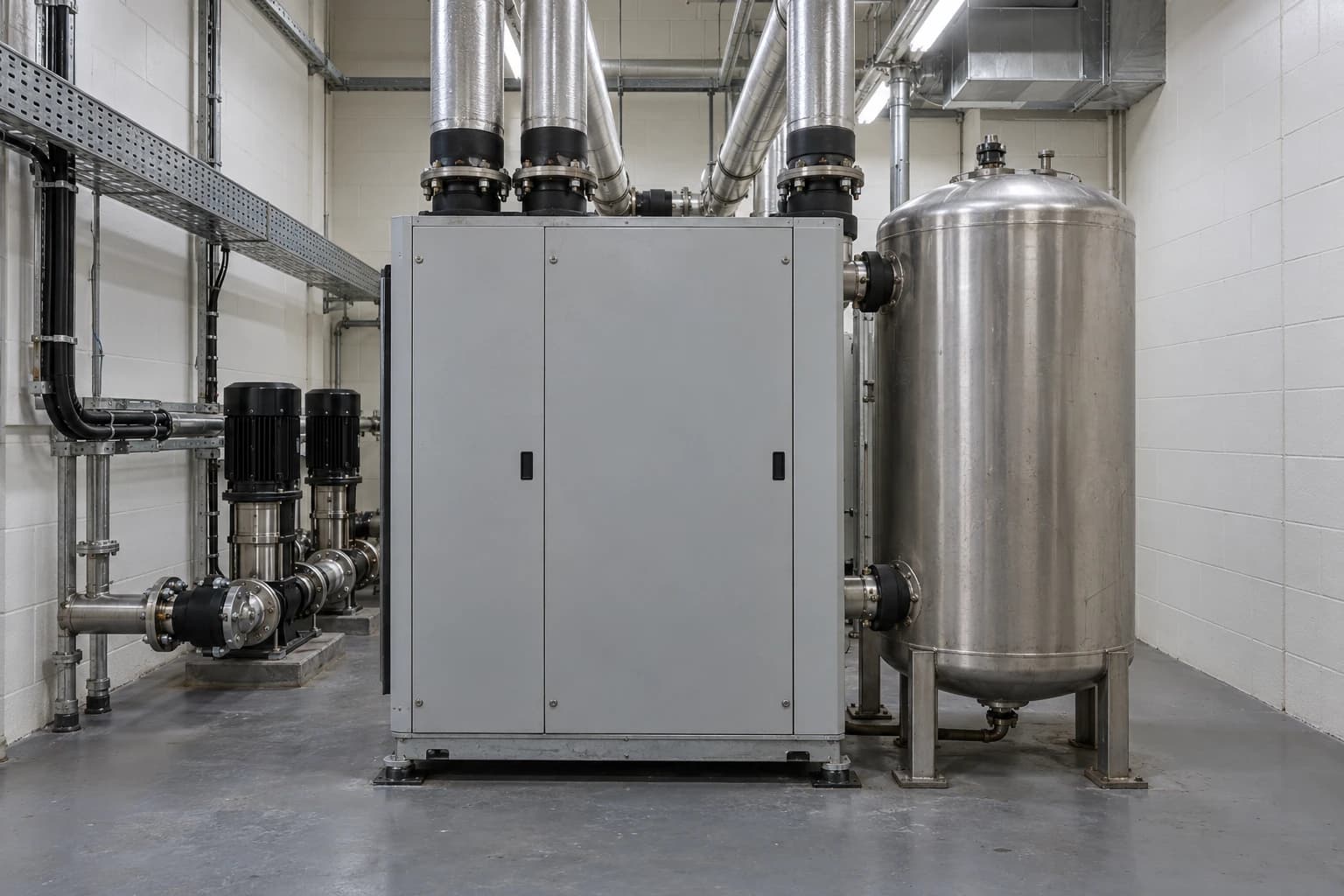
Heat pumps can upgrade 30-40°C refrigeration condenser heat for CIP and room heating.
Heat integration in pharmaceutical manufacturing is the systematic matching of hot streams that need cooling with cold streams that need heating, so that heat is reused before steam, boilers or refrigeration utilities supply it.
ISPE reports that HVAC can account for approximately 70% of energy use in a pharmaceutical facility. Heating, cooling, dehumidification and reheat duties therefore offer utilities managers an opportunity to cut gas use and Scope 1 and 2 emissions without disturbing validated production.
The opportunity sits between systems. A refrigeration condenser rejects heat while a cleanroom air handling unit needs reheat. A chilled-water plant removes heat while a CIP skid warms wash solution. A tank cooling duty operates beside a building heating load. Heat integration identifies these overlaps, quantifies their value and turns them into a controlled heat exchanger network.
Why heat integration matters in pharmaceutical manufacturing
Simultaneous heating and cooling create recoverable value
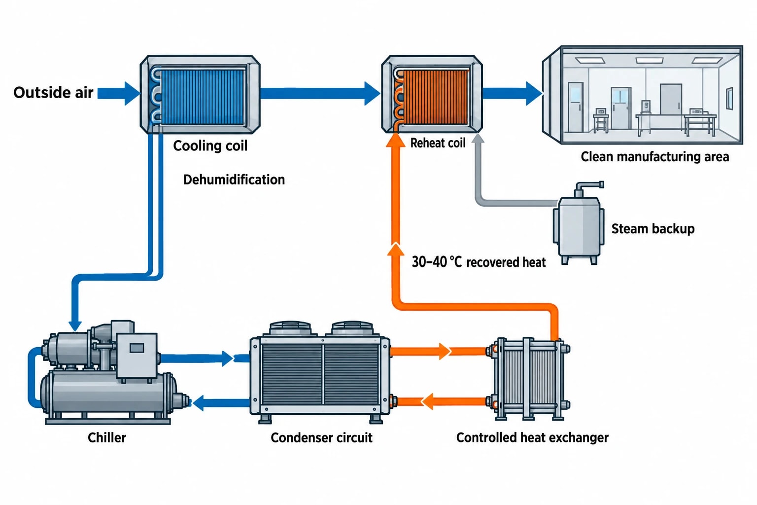
Pharmaceutical sites commonly operate steam boilers, chillers, hot-water generators and cooling systems at the same time. The arrangement is reliable, familiar and often wasteful. A chiller rejects heat to a condenser circuit while another utility consumes fuel or electricity to create a heating duty elsewhere on site.
This pattern is particularly clear in GMP HVAC. Outside air often needs cooling below its required supply temperature to remove moisture, then reheating to meet room conditions. High air-change rates, pressure cascades and filtration duties make this a persistent load in clean manufacturing areas.
Heat integration shifts attention from individual equipment efficiency to the whole thermal system. A highly efficient boiler still consumes fuel if usable condenser heat is discharged. A chiller with good seasonal efficiency still rejects useful heat if a nearby low-temperature heating load is served by steam.
The practical objective is to reduce utility demand while retaining the temperature stability, availability, cleanability and documented control required by pharmaceutical production.

Pinch analysis identifies the thermodynamic minimum energy requirement of your process — then designs the heat exchanger network to achieve it.
How pinch analysis identifies waste-heat opportunities
From process data to a heat exchanger network
Pinch Analysis provides a method for heat integration in pharmaceutical manufacturing. Engineers map the site’s hot streams, which require cooling, and cold streams, which require heating. They establish the temperature range, heat duty, timing, flow rate, heat-transfer constraints and operating conditions for each stream.
The resulting composite curves reveal the pinch point: the closest feasible temperature approach between the combined hot and cold streams. This point divides the system into two thermodynamic regions and establishes targets for minimum heating and cooling utilities.
For maximum energy recovery, pinch methodology follows three design rules:
- No heat transfer crosses the pinch.
- No external heating is supplied below the pinch.
- No external cooling is supplied above the pinch.
These rules establish a theoretical target. A pharmaceutical heat exchanger network then needs to work around batch schedules, sanitation, physical routing, redundancy and GMP control requirements.
A useful study avoids relying only on annual averages. Batch plants can show large, short-duration CIP, sterilisation, solvent-recovery and tank-conditioning loads. A recovery opportunity that looks strong over a year may disappear when one system operates at night and its heat sink operates only during a weekday production campaign.
The data set should capture representative operating modes, including campaign changeovers, wash cycles, summer dehumidification, winter heating, shutdowns and peak production. It should distinguish between process streams, HVAC utilities, clean utilities and contaminated streams.
| Stream information | Why it matters for heat integration |
|---|---|
| Supply and target temperatures | Establishes whether direct recovery or a heat pump is feasible |
| Heat duty and flow rate | Sizes exchangers, pumps and thermal storage |
| Batch timing and duration | Tests whether source and sink operate together |
| Fluid composition | Determines materials, cleanability, fouling and segregation needs |
| Required temperature control | Defines control-valve authority, buffer capacity and alarm requirements |
| GMP status | Identifies qualification, change-control and validation implications |
Temperature quality determines the right use
A site may discharge a large quantity of heat at a low temperature, yet have little direct use for it. Heat at 30°C cannot perform the same duty as clean steam. Its value depends on the temperature lift between source and sink.
Direct recovery is usually the first option where compatible hot and cold streams overlap at suitable temperatures. A heat pump can then raise lower-grade heat to a useful hot-water temperature. Thermal storage can separate source and sink in time, allowing a short refrigeration load to support a longer CIP or HVAC reheat demand.
The chosen minimum temperature approach also requires engineering judgement. A very small approach temperature can increase recovered heat but demand a much larger exchanger surface area, tighter control and more cleaning. In pharmaceutical service, recoverability must sit alongside maintainability and hygienic design.
Where pharmaceutical plants can recover heat
Refrigeration condensers and chilled-water systems
A 2024 study of pharmaceutical process heat identified refrigeration systems as a major source of excess heat at 30 to 40°C. The study identified heat pumps as a route to upgrade this energy for CIP systems, room heating, tank temperature control and defrosting.
This is a strong starting point because refrigeration and chilled-water systems often operate throughout the year. Their condenser heat is predictable, and many sites also have low-temperature hot-water demand from HVAC or cleaning operations.
A heat-recovery chiller can produce chilled water while transferring condenser-side heat into a hot-water circuit. It performs best when heating and cooling loads occur together. Central utility design should therefore examine cooling and heating demand profiles before selecting capacity.
Low-temperature hot water often offers the most accessible sink. Space-heating coils, preheat coils, dehumidification reheat, wash-water preheat and jacketed tank duties can accept lower temperatures than pure-steam or terminal sterilisation duties.
HVAC exhaust and reheat loads
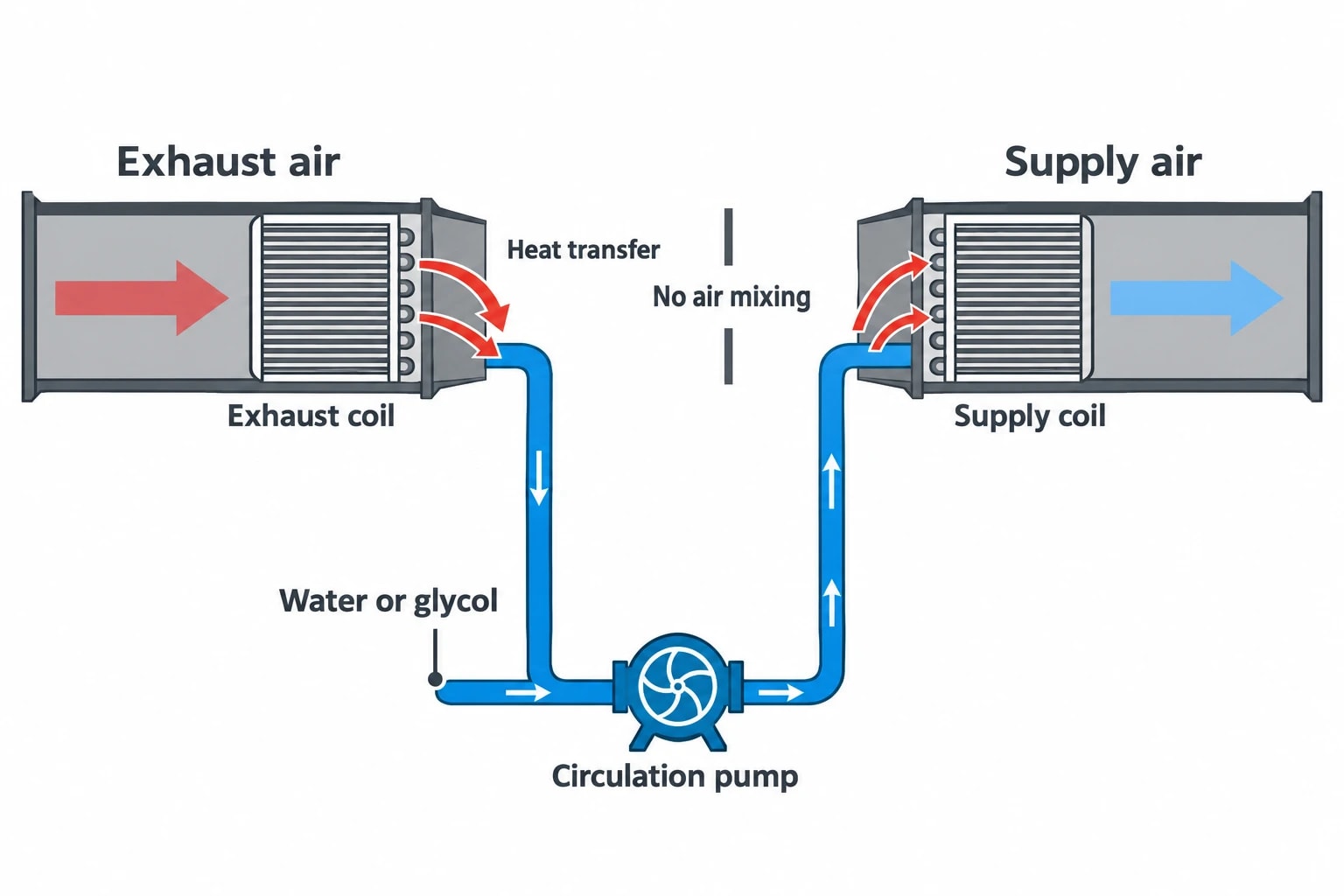
Air handling systems can offer another recovery route. A runaround loop transfers energy through separate exhaust and supply-air coils connected by water or glycol, avoiding direct mixing of air streams. That separation is valuable where process exhaust presents contamination, solvent or containment concerns.
ISPE describes a pharmaceutical project that combined several air handling and exhaust streams through an intelligent runaround loop. Reported peak recovery exceeded 25% during cooling conditions and 30% during heating conditions. These figures describe a particular site and design rather than a universal performance expectation, but show why exhaust recovery should be assessed alongside chilled-water integration.
CIP, tank control and utility preheat
CIP systems often create repeated heating loads for wash solutions, rinses and associated vessels. Heat recovery can preheat incoming water or provide low-temperature hot water upstream of a final heating stage. This lowers the duty imposed on steam or electric heating without changing the validated final temperature requirement.
Tank heating and cooling can also create useful pairings, especially where campaign schedules produce stable temperature-control demand. The heat exchanger arrangement requires careful assessment of product-contact risk, cleaning strategy, pressure differential and cross-contamination consequences.
Warm CIP return should receive particular scrutiny. Its chemical composition, residues and contamination risk usually make direct reuse inappropriate. An intermediate loop and suitably specified heat exchanger can isolate the recovery circuit where the site risk assessment supports the arrangement.
Heat pumps link cooling, dehumidification and heating
Heat pumps upgrade low-grade heat
The central technical opportunity is often the link between chilled water and low-temperature hot water. A heat pump removes heat from a cooling source and delivers it at a higher temperature to a useful sink. In a pharmaceutical setting, this can connect refrigeration condenser heat, chilled-water return or process cooling demand with HVAC heating and reheat loads.
The heat pump should be assessed as part of the network, rather than as a boiler replacement in isolation. Its performance depends on source temperature, required delivery temperature, load matching, part-load operation and control stability. A smaller temperature lift generally supports better performance.
Low-temperature heating systems expand the number of viable applications. They can absorb recovered energy from chillers and heat pumps before higher-temperature utilities serve duties that require them. This preserves higher-grade heat for genuinely higher-temperature tasks.
Protect sterilisation duties from inappropriate substitution
Heat recovery can reduce the upstream energy required by sterilisation-related systems, but it does not remove the need for scientifically designed and controlled sterilisation cycles.
EU GMP Annex 1, section 8.35, requires the selection, design and location of sterilisation equipment and its cycle or programme to rest on scientific principles and data demonstrating repeatability and reliability. It also requires defined parameters, with critical parameters controlled, monitored and recorded.
Recovered heat should therefore commonly support preheat, utility generation or non-product-contact duties around sterilisation equipment. Pure steam, steam-in-place and terminal sterilisation systems require their own qualified heat source, validated cycle and documented operating controls.

Pinch analysis identifies the thermodynamic minimum energy requirement of your process — then designs the heat exchanger network to achieve it.
GMP controls shape every heat-recovery project
Air pressure, airflow and contamination control
Heat integration changes temperatures, flow rates, control sequences and sometimes duct or pipe routing. These changes can alter cleanroom pressure relationships and airflow patterns.
EU GMP Annex 1, section 4.14, states that cleanrooms should receive filtered air that maintains positive pressure or airflow relative to a lower-grade background under all operational conditions. It gives a 10 Pa minimum pressure differential between adjacent rooms of different grades as a guidance value, while recognising that containment requirements may require a different arrangement.
Section 4.15 requires airflow patterns within cleanrooms and zones to be visualised. Studies must show that lower-grade air does not enter higher-grade areas and that air does not pass from less clean areas, operators or equipment towards higher-grade zones. Studies take place both at rest and in operation, with video records retained.
A heat-recovery scheme affecting air handling units should therefore assess its impact on:
- Supply and extract airflow balance
- Room pressure differentials and alarms
- Dehumidification and reheat control
- Airflow visualisation studies
- Filter performance and maintenance access
- Cleanroom temperature and humidity ranges
Change control must start at concept stage
Quality, engineering and operations teams should define the change boundary before selecting equipment. The boundary may be limited to a non-classified utility area, or it may affect systems that influence cleanroom conditions, CIP performance, sterilisation or process temperature control.
A disciplined project typically develops a heat-and-mass balance, process description, hygienic design assessment, control philosophy, alarm assessment and commissioning plan before installation. The validation impact then follows the actual system risk rather than assumptions based only on energy savings.
The most durable projects establish clear ownership for setpoints, deviations, calibration, heat exchanger cleaning, leak detection and seasonal operating modes. Energy performance should be monitored alongside GMP operating parameters so that a loss of recovery does not become a hidden increase in boiler or chiller load.
Solvent-handling heat recovery requires DSEAR assessment
Segregation and hazardous-area design come first
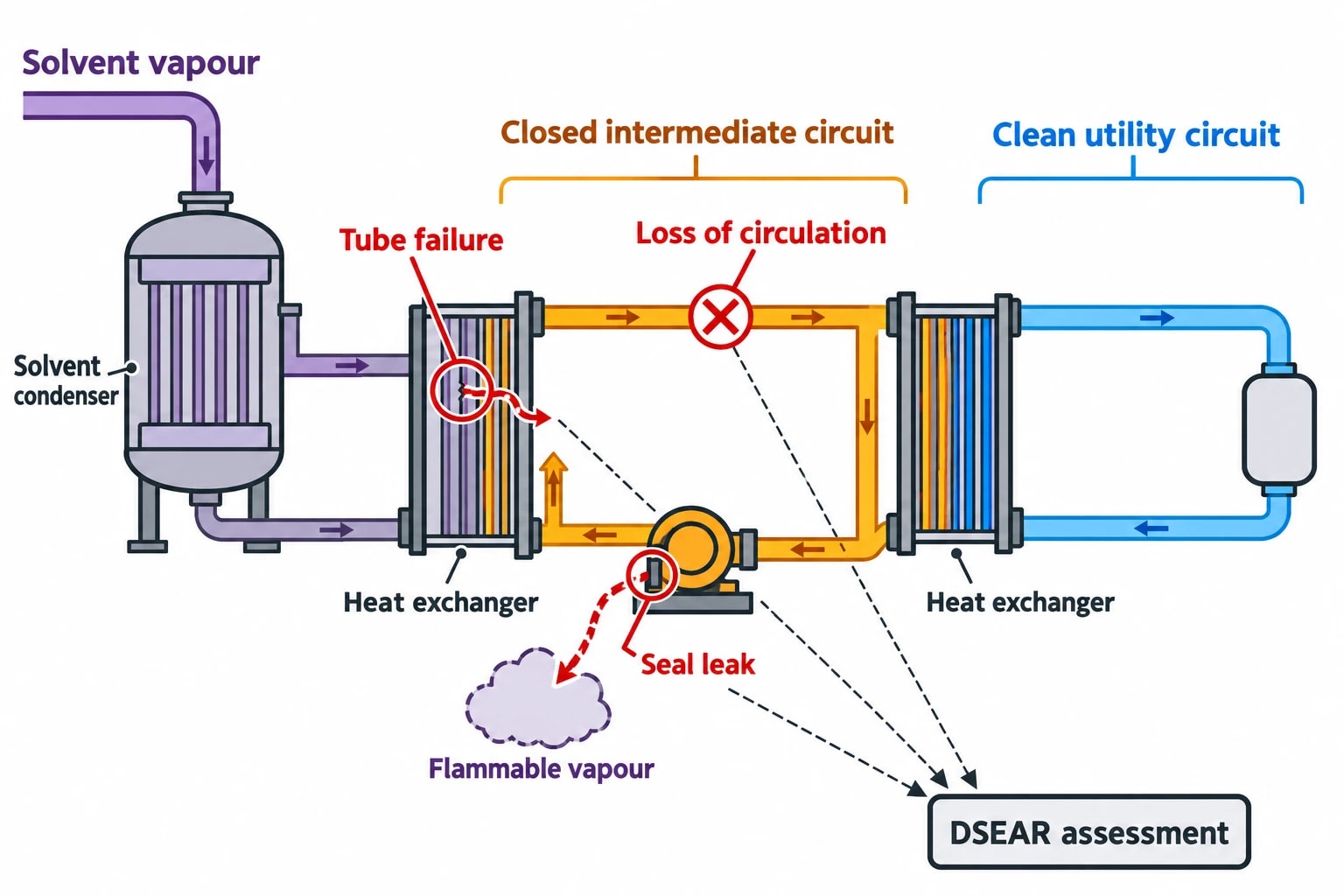
Solvent extraction, drying and recovery systems can present attractive thermal sources, particularly through condensers and exhaust streams. They also introduce flammable vapours, hazardous zones and ignition risks.
The UK Dangerous Substances and Explosive Atmospheres Regulations 2002, SI 2002/2776, require employers to assess fire and explosion risks from dangerous substances and eliminate or reduce those risks so far as is reasonably practicable. The Regulations require hazardous places where an explosive atmosphere may occur to be classified into zones.
For solvent-related heat recovery, the design assessment should address:
- Process fluid composition and credible leak paths
- Hazardous-area classification and equipment suitability
- Separation between solvent-bearing and clean utility circuits
- Ignition sources introduced by pumps, motors, instrumentation and hot surfaces
- Ventilation, condensate handling and pressure relief arrangements
- Inspection, maintenance and emergency procedures
Indirect recovery through a closed intermediate circuit may provide segregation, but the full arrangement still needs a DSEAR-informed assessment. A heat exchanger tube failure, seal leak or loss of circulation can create risks absent from a simple energy balance.
A practical route to heat integration in pharmaceutical manufacturing
Start with measured utility and process data
The first project should focus on a site area with stable simultaneous heating and cooling loads. Chilled-water and heating-hot-water systems, HVAC reheat and CIP preheat are often suitable candidates. A plant-wide target can follow once the team has measured actual temperatures, duties and operating schedules.
A useful delivery sequence is:
- Map major heating and cooling streams, including batch timing and temperature ranges.
- Build pinch targets for each representative operating mode.
- Identify direct heat recovery before assessing heat-pump temperature lifts.
- Screen options for GMP, DSEAR, maintainability and validation impact.
- Develop the control philosophy, alarms, bypass arrangements and energy monitoring.
- Commission against thermal, operational and quality acceptance criteria.
- Review seasonal performance and revise operating schedules where load patterns change.
The strongest schemes match a continuous source with a continuous sink, use low-temperature hot-water loads before higher-grade utilities, and preserve independent qualified duties for sterile processing. Pinch Analysis gives utilities managers a disciplined way to find those matches.
This article reflects the independent analysis and editorial opinion of EnerTherm Engineering. Product names, trademarks, and brands mentioned belong to their respective owners. EnerTherm Engineering is not affiliated with, endorsed by, or a licensee of any third-party software or product mentioned unless explicitly stated.

Managing Director — EnerTherm Engineering
Dr. François Pierrel is Managing Director of EnerTherm Engineering with over two decades of expertise in thermal design, heat transfer, and industrial energy optimisation. He holds a PhD in Heat Transfer from Cranfield University and a Post-Doctorate from Heriot-Watt University.
