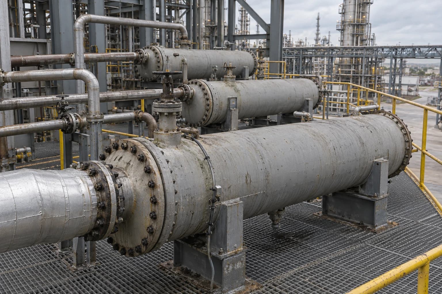
Heat Exchanger Retrofits: Pinch Analysis Cuts Utility Use
A refinery study found about 10.5% energy-demand savings from minor structural changes.
A heat exchanger network retrofit pinch analysis reduces steam, fuel and cooling demand by identifying where an existing process can recover more heat between its hot and cold streams. A 2017 refinery study reported approximately 10.5% lower energy demand from minor structural modifications to a crude preheat train, recovering about 60% of the energy-saving potential identified against the Pinch Analysis benchmark.
For chemical plants, refineries and food factories, that distinction matters. A new heat exchanger network can be designed around ideal stream matches. An operating plant has existing shells, tube bundles, piping corridors, pumps, control valves, shutdown windows, pressure-drop limits and production commitments.
A heat exchanger network retrofit needs a practical route from the thermodynamic target to a modification that can be installed, commissioned and operated safely. Pinch Analysis makes that route visible.
Why existing heat exchanger networks consume excess utility
A heat exchanger network transfers heat from process streams that must be cooled to streams that need heating. In a refinery crude preheat train, hot products and pumparounds heat incoming crude before the fired heater. In food processing, hot effluent or pasteurised product can preheat incoming product. Chemical sites use similar arrangements around reactors, distillation columns, evaporators and dryers.
Over time, the network can drift away from its original heat-recovery performance.
Fouling, changed duty and operating flexibility
Fouling reduces heat-transfer performance and raises the temperature difference needed to achieve the same duty. Plants may compensate by increasing steam flow, fired-heater duty or cooling-water use. Cleaning may restore part of the original duty, but it does not resolve a network that no longer matches current process conditions.
Feedstock composition, throughput, product specification and campaign operation can also alter stream heat capacities and temperature ranges. A network designed for one crude slate or production rate may create utility penalties under another.
Sites often accumulate local modifications. A bypass installed to stabilise control, a new heat exchanger added for debottlenecking, or a rerouted stream may each solve an immediate problem. Together, they can create cross-pinch heat transfer and unnecessary utility demand.
The cost of cross-pinch heat transfer
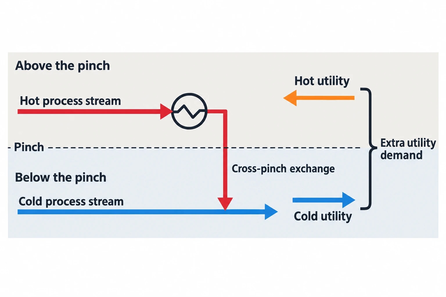
The pinch divides the process into two thermodynamic regions. Above the pinch, the process has a net heat deficit. Below it, the process has a net heat surplus. Heat transferred across that boundary forces additional hot and cold utility use.
In a retrofit, cross-pinch exchange is not automatically removed. It may be necessary because of pressure constraints, layout, heat-exchanger area or controllability. Pinch Analysis shows its utility penalty and allows engineers to compare that penalty with the cost and disruption of changing the match.
The question for each candidate modification is whether the recovered heat reduces a real utility duty under normal operation, or merely moves heat around the network.

Pinch analysis identifies the thermodynamic minimum energy requirement of your process — then designs the heat exchanger network to achieve it.
How pinch analysis establishes the retrofit target
Pinch Analysis starts with stream data rather than equipment drawings. Engineers define hot streams that need cooling and cold streams that need heating. Each stream requires supply and target temperatures, heat-capacity flowrate, phase-change duty where relevant, operating pressure and expected operating range.
Selecting the minimum temperature approach
The minimum temperature approach, commonly written as ΔTmin, is the smallest practical temperature difference between matched process streams. It reflects heat-exchanger type, fouling allowance, control needs, heat-transfer coefficients and the trade-off between heat-exchanger area and utility use.
A small ΔTmin can reduce theoretical utility targets, but it may demand more area or create impractical heat-exchanger duties. A large ΔTmin gives a cheaper theoretical network while increasing fuel, steam and cooling use. Retrofit work should test a range rather than treat a historic design value as fixed.
For existing heat exchangers, the selected approach must be checked against actual terminal temperature differences, installed area, pressure drop and expected fouling. A target that assumes new high-area heat exchangers has limited value if the project permits only shell-side changes during a short turnaround.
Composite curves and the energy target
Composite curves combine the thermal demand of all hot and cold streams. They show the temperature intervals where process heat is available and where it is required. The closest approach identifies the pinch and establishes minimum hot and cold utility targets for the chosen ΔTmin.
The target is an energy benchmark, not a buildable retrofit specification.
A refinery preheat train can sit well above its benchmark because heat-exchanger area is in the wrong service, hot-stream heat is recovered at too low a temperature for crude preheat, or a pressure-drop limit prevents a better match. The gap between current utility consumption and the target represents opportunity, but not all of it is economically or operationally recoverable.
Energy targeting must reflect real operations
A credible heat exchanger network retrofit pinch analysis uses more than a single design case. It should examine normal rates, low-throughput operation, different feedstocks, seasonal cooling conditions and product campaigns where they materially affect the heat balance.
A useful basis includes:
- Validated process temperatures, flowrates and pressures from plant data.
- Current heat-exchanger duties calculated from reconciled measurements.
- Utility consumption by operating mode.
- Heat-exchanger area, type, design temperatures and allowable pressure drops.
- Fouling history and cleaning intervals.
- Control constraints, bypasses and minimum-flow requirements.
- Planned production changes that could alter stream availability.
Poor measurements can make an apparent pinch violation look attractive when the heat exchanger is already operating close to its practical limit.
Turning the pinch target into retrofit options
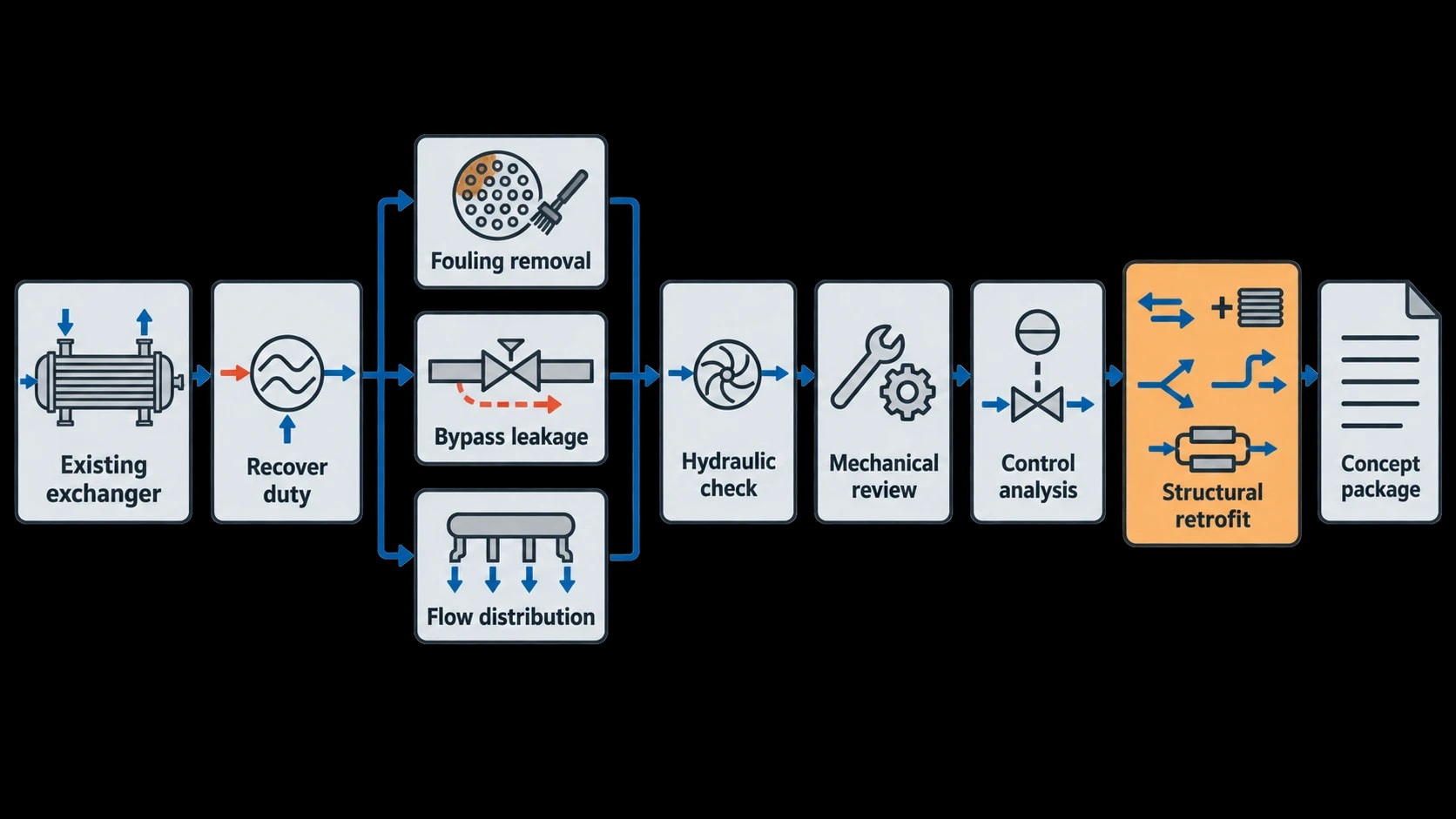
A retrofit should begin with the least disruptive options. Pinch methods can identify high-value areas, while hydraulic checks, mechanical review and process-control analysis determine whether a modification is workable.
Recover duty before adding new equipment
The first review should establish whether existing heat-exchanger surface can transfer more heat. Fouling removal, revised cleaning intervals, corrected bypass leakage and changed flow distribution may recover duty without changing the network topology.
Cleaning a heat exchanger can increase pressure drop or uncover a control issue previously masked by low duty. The project team should assess duty, pressure drop, control-valve authority and downstream temperature limits together.
Modify matches and exchanger duties
Where cleaning or operating changes cannot close the energy gap, retrofit options may include:
- Reassigning a heat exchanger to a more suitable stream match.
- Increasing surface area through a bundle replacement or additional shell.
- Splitting a stream to use available temperature driving force more effectively.
- Moving a utility heat exchanger to avoid cross-pinch duty.
- Adding a process-process heat exchanger where heat is rejected before it can serve a cold process stream.
- Reconfiguring series and parallel arrangements to improve temperature driving force.
Each option may affect pump head, control stability, heat-exchanger metallurgy, relief scenarios, maintenance access and start-up procedures. A good concept package records these implications before capital approval.
Use temperature driving force to locate practical changes
Temperature-driving-force analysis is useful for existing networks because it shows where a heat exchanger lacks sufficient temperature difference and where a changed match may unlock recoverable heat.
The 2017 refinery study used temperature-driving-force curves to examine a modern crude preheat train. Its result came from minor structural modifications rather than complete network replacement. It demonstrates that a mature network can still contain material opportunity when Pinch Analysis is combined with equipment-level constraints.
A practical workflow for heat exchanger network retrofit pinch analysis
A staged workflow reduces the risk of carrying a theoretical target into an unbuildable project.
| Stage | Engineering purpose | Typical output |
|---|---|---|
| Data reconciliation | Establish trusted stream and utility duties | Validated stream table and current heat balance |
| Pinch targeting | Calculate minimum utility demand and pinch location | Composite curves and utility targets |
| Network diagnosis | Identify cross-pinch matches, utility placement and area constraints | Ranked list of heat-recovery opportunities |
| Retrofit synthesis | Develop feasible changes within mechanical and operational limits | Retrofit schemes and updated heat-exchanger duties |
| Screening | Compare capital cost, utility savings, emissions and outage needs | Shortlist for process hazard and detailed design review |
| Verification | Confirm installed performance after commissioning | Measured duty, utility reduction and operating instructions |
Start with the current network, not the PFD
A process flow diagram may show the intended structure, but it rarely captures every bypass, isolation arrangement, standby heat exchanger or temporary tie-in. Heat exchanger network retrofit work needs an as-operated network map based on line walks, control narratives, datasheets and current plant data.
The network should distinguish between continuous and intermittent streams. A batch cleaning line, intermittent product cooler or periodically available hot stream cannot support the same degree of heat recovery as a continuous refinery side draw.
Screen modifications against constraints early
The most promising heat-recovery match can fail at screening because its added pressure drop exceeds pump margin or its new outlet temperature affects downstream separation. A structured screening table should cover:
- Heat duty and temperature approach.
- Heat-exchanger area and heat-transfer coefficient.
- Tube-side and shell-side pressure drop.
- Corrosion and fouling risk.
- Control response during rate changes.
- Need for isolation, bypassing and cleaning.
- Tie-in scope and turnaround duration.
- Effects on fired-heater duty, steam balance and cooling load.
This moves the discussion from theoretical savings to engineering decisions and prevents a site from selecting a low-capital modification that introduces chronic operability problems.

Pinch analysis identifies the thermodynamic minimum energy requirement of your process — then designs the heat exchanger network to achieve it.
Production constraints define the retrofit strategy
Plant availability often determines which heat exchanger network retrofit option proceeds. A refinery may have only a defined turnaround window. A food plant may schedule work around short sanitation shutdowns. A chemical producer may need to preserve campaign flexibility.
Design for commissioning and control
New recovery duties alter temperature-control loops. A cold-stream outlet may rise rapidly when a hot stream becomes available, or fall during a trip. Engineers should check control-valve rangeability, bypass logic, heat-exchanger bypass failure positions and temperature alarms.
A retrofit should also consider start-up and shutdown. Process-process exchange that performs well at normal throughput may provide little duty during warm-up, leaving a utility heat exchanger to cover the temperature gap. The operating procedure must reflect that condition.
Measure savings after start-up
A measured-and-verified result protects the energy case and the operating team. Baselines should account for throughput, feed quality, ambient cooling conditions and product mix. Fuel, steam and cooling changes should be compared with the pre-project operating basis rather than a single historic month.
The measurement plan should identify the meters that provide evidence for the change. Fired-heater fuel flow, steam flow, feed temperatures, heat-exchanger inlet and outlet temperatures, cooling-water flow and pump power may be relevant. Engineers should capture enough data before the shutdown to establish a defensible baseline.
UK and EU drivers for heat recovery projects
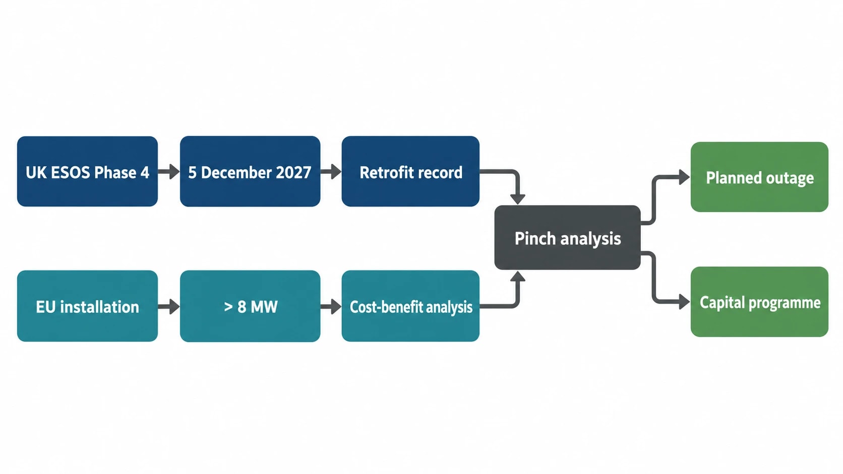
Energy-efficiency legislation gives additional weight to well-documented heat exchanger network retrofit opportunities.
ESOS Phase 4 and process heat
The UK Energy Savings Opportunity Scheme is governed by the Energy Savings Opportunity Scheme Regulations 2014, SI 2014/1643, as amended. Phase 4 applies to qualifying large undertakings and requires notification of compliance by 5 December 2027.
Current Phase 4 guidance requires participants to include progress against earlier action-plan commitments in their assessment. Where proposed measures have not been implemented, the organisation must explain why. This increases the value of a retrofit study that records the utility baseline, technical constraints, estimated savings and reasons for selecting or rejecting each option.
For process sites, heat exchanger network retrofit pinch analysis can provide evidence for a targeted measure. It identifies significant energy consumption, documents the practical saving opportunity and separates projects that can be delivered during a planned outage from those requiring a larger capital programme.
EU waste-heat assessments
For relevant EU facilities, Directive (EU) 2023/1791 requires a cost-benefit analysis for new industrial installations, and existing installations undergoing substantial refurbishment, with total rated thermal input above 8 MW. The analysis assesses on-site and off-site waste-heat use.
For on-site waste-heat recovery, heat exchangers, heat pumps and heat-to-power technologies may be assessed. Heat exchanger network retrofit analysis tests whether available process heat can reduce on-site utility demand before more complex upgrading or export schemes are considered.
What a strong retrofit business case looks like
The business case should state the expected utility reduction in physical units, the fuel or steam source displaced, the relevant carbon factor, installed cost, outage requirement and sensitivity to operating conditions. It should also make clear which benefits depend on feedstock, throughput or heat-exchanger cleanliness.
A project that moves a pinch target closer to plant operation may be valuable even if it cannot reach the theoretical minimum utility demand. The refinery study illustrates the practical standard for retrofit work: recover heat where the plant can use it, protect operability and quantify the remaining gap for future capital decisions.
This article reflects the independent analysis and editorial opinion of EnerTherm Engineering. Product names, trademarks, and brands mentioned belong to their respective owners. EnerTherm Engineering is not affiliated with, endorsed by, or a licensee of any third-party software or product mentioned unless explicitly stated.

Managing Director — EnerTherm Engineering
Dr. François Pierrel is Managing Director of EnerTherm Engineering with over two decades of expertise in thermal design, heat transfer, and industrial energy optimisation. He holds a PhD in Heat Transfer from Cranfield University and a Post-Doctorate from Heriot-Watt University.
