Why FCC Unit Pinch Analysis Can Cut Fuel Use by 8-25%
Ipieca reports refinery pinch projects can cut purchased fuel by 8-25%.
Fluid catalytic cracking unit pinch analysis is a thermodynamic targeting method that identifies where an FCC unit can recover more process heat and reduce its need for fired fuel, steam and cooling utilities.
Ipieca reports a guideline reduction of 8% to 25% in purchased heating fuel for pinch-analysis applications in oil refining. This is a refinery-wide benchmark, not an FCC-unit performance guarantee. An FCC study identifies the unit’s heat-recovery limit and the practical changes needed to approach it.
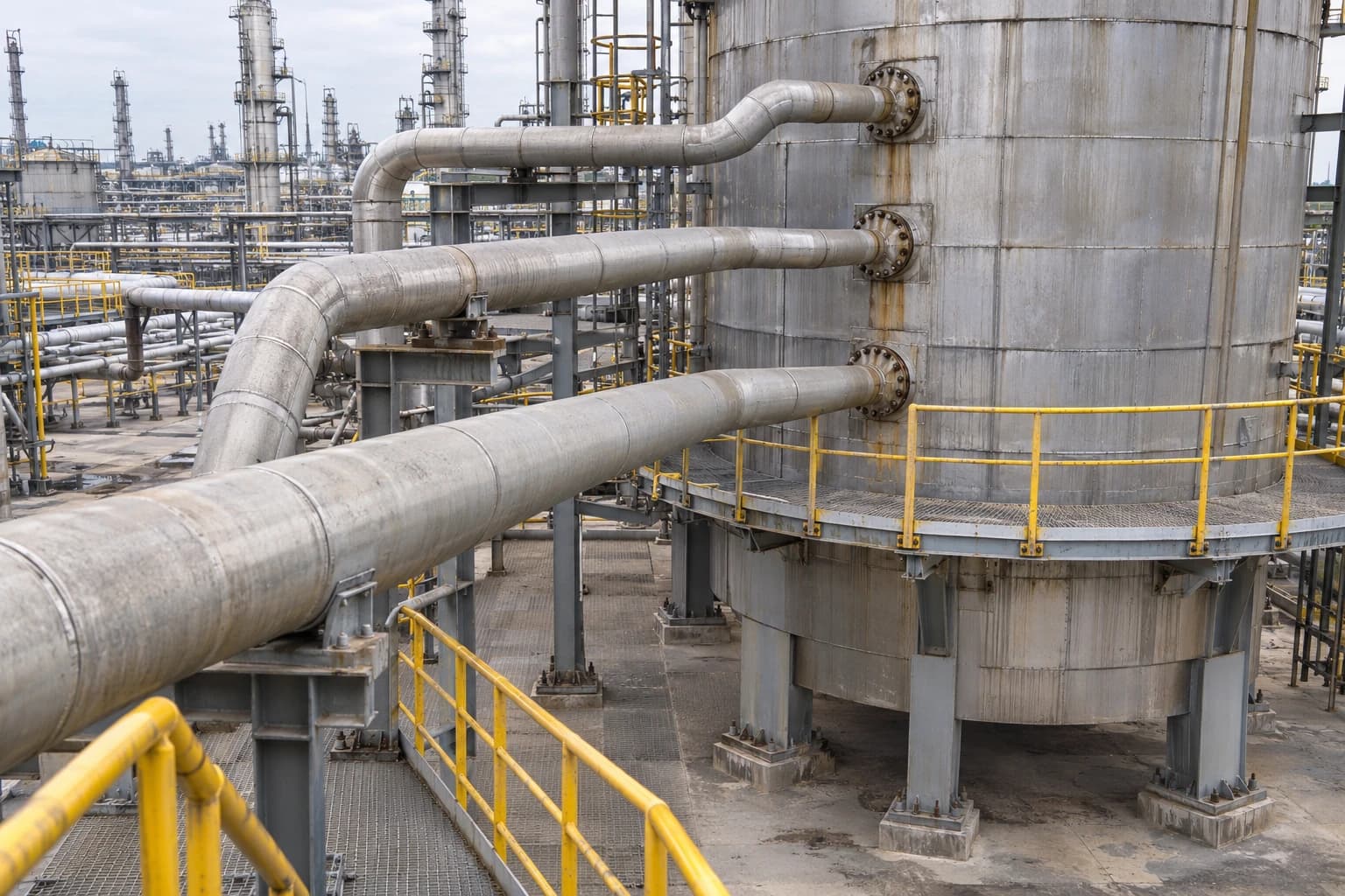
An FCC unit combines hot regenerated catalyst, reactor effluent, main-fractionator pumparounds, steam generation and substantial fired-duty demand. This concentration of heat sources and sinks makes it an important target for refinery process integration. Temperature quality, rather than the gross quantity of available heat, is usually the limiting factor.
Why FCC units are strong candidates for pinch analysis
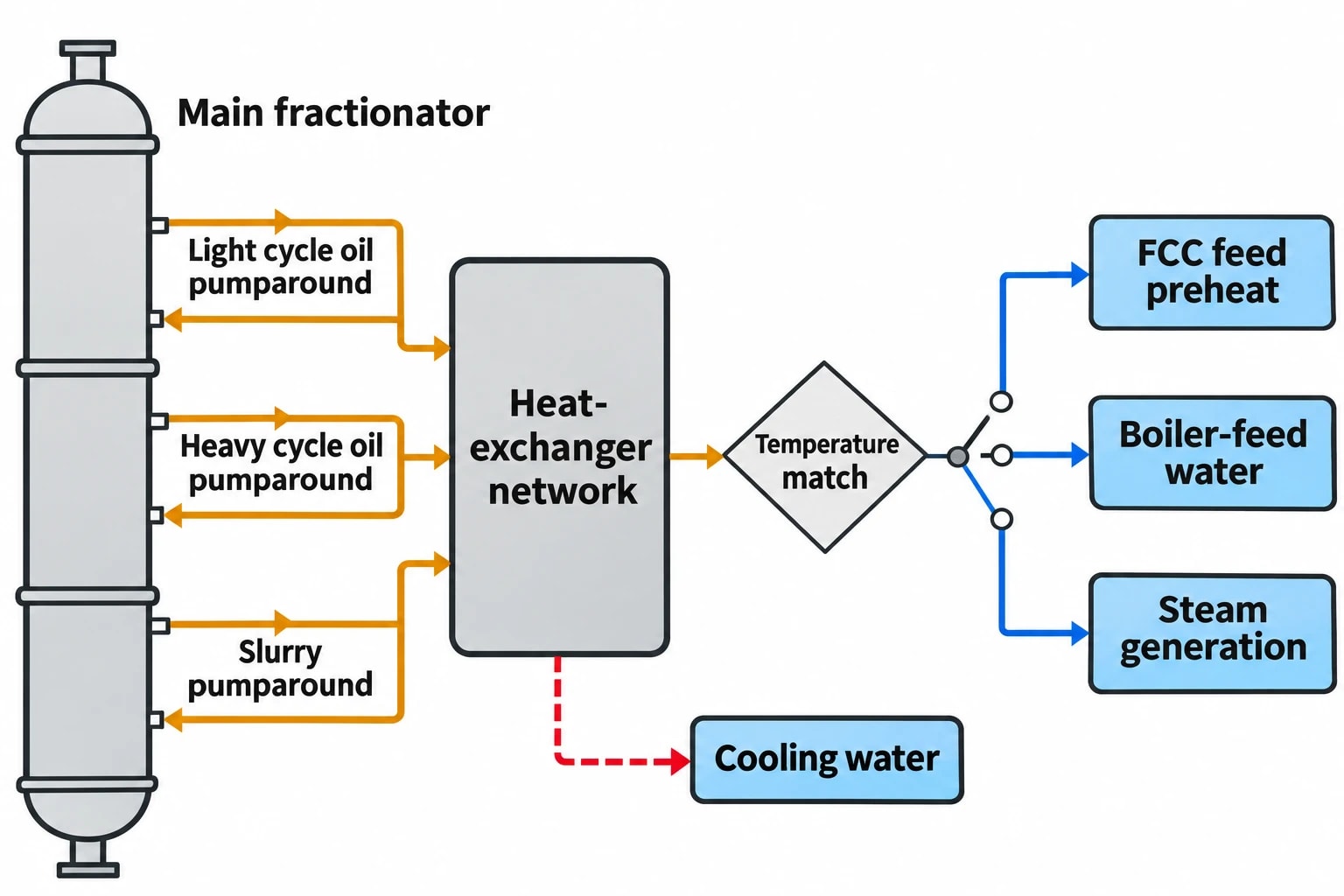
Coke combustion in the regenerator generates high-temperature heat. Hot regenerated catalyst transfers much of that energy to the riser, supporting feed vapourisation and endothermic cracking. Cracked vapour then enters the main fractionator, which rejects heat through slurry circuits, pumparounds, side draws and overhead systems.
This arrangement produces a tightly connected heat-exchanger network. Heat may be rejected at a useful temperature while another part of the unit continues to burn fuel or consume steam.
The main fractionator controls much of the recoverable heat
The main fractionator receives reactor effluent and separates products including slurry, heavy cycle oil and light cycle oil. Its pumparounds remove heat at different temperature levels and return liquid to selected points in the column.
That duty can support FCC feed heating, boiler-feed-water heating, steam generation or other refinery process duties. The right destination depends on the temperature match, fouling risk, product-quality constraints and refinery-wide utility balance.
Common warning signs include:
- A fired heater receives feed that could be preheated further.
- A pumparound rejects duty to cooling water while a nearby cold process stream remains available.
- Steam heats a reboiler while a process stream rejects heat at a suitable temperature.
- An exchanger bypass remains open after an operating change.
- Fouling has reduced preheat duty and increased heater firing.
A review of individual exchangers can expose poor performance. Fluid catalytic cracking unit pinch analysis examines the entire network and identifies whether an apparently sensible exchanger pairing blocks a more valuable heat-recovery opportunity elsewhere.
Regenerator heat requires careful boundaries
Regenerator heat has high value, but an FCC heat-integration project must preserve combustion performance, catalyst circulation, emissions control and equipment integrity. Flue-gas heat recovery can involve waste-heat boilers, subject to the site configuration, particulate loading, corrosion risks and downstream emissions equipment.
Commission Implementing Decision (EU) 2014/738 identifies pinch analysis, heat integration, and heat and power recovery as energy-efficiency techniques within the refining BAT conclusions. It lists waste-heat boilers and FCC expanders or power-recovery equipment among energy-recovery devices.
The decision also contains dedicated BAT conclusions for catalytic cracking and regenerator emissions. A heat-recovery proposal needs review by process, inspection, maintenance, combustion, control and environmental specialists before a refinery commits to a modification.

Pinch analysis identifies the thermodynamic minimum energy requirement of your process — then designs the heat exchanger network to achieve it.
What fluid catalytic cracking unit pinch analysis measures
Pinch analysis sets thermodynamic targets before selecting equipment changes. Engineers define the FCC unit’s hot and cold streams, establish supply and target temperatures, and account for heat-capacity flowrates, phase changes and operating constraints.
The study then applies a minimum temperature approach, usually described as ΔTmin. This reflects exchanger service, fouling tendency, pressure drop, available area and retrofit practicality.
Building an FCC stream list
The precise model depends on feedstock, product slate, regenerator design and refinery integration. A typical FCC pinch model may include the following streams.
| Stream group | Pinch-study role | Key practical constraint |
|---|---|---|
| Reactor effluent to main fractionator | Hot stream | Fractionator pressure and separation performance |
| Main-fractionator pumparounds | Hot streams | Product draw temperatures and column heat balance |
| Slurry and cycle-oil circuits | Hot streams | Fouling, solids handling and cleanability |
| Fresh and recycle FCC feed | Cold streams | Viscosity, heater inlet limits and pressure drop |
| Side-stripper or gas-plant reboilers | Cold streams | Required boiling temperature and pressure |
| Boiler-feed water and condensate | Cold streams | Steam-header demand and water-quality requirements |
| Regenerator flue-gas recovery | Hot stream | Erosion, corrosion, particulate loading and emissions equipment |
| Air-cooler and cooling-water duties | Cold utility demand | Seasonal conditions and turndown |
Historian data, laboratory results and heat-and-material-balance models should be reconciled before composite curves are generated. A clean design case rarely represents normal operation. Feed quality, throughput, catalyst circulation, combustion mode and ambient conditions can all alter the unit heat balance.
Finding the pinch temperature
The pinch temperature marks the tightest temperature constraint in the network. Above the pinch, the process requires external heating. Below it, the process requires external cooling. Heat transferred across the pinch increases both utility requirements beyond the thermodynamic minimum.
In an FCC unit, the analysis may show that:
- Low-temperature pumparound duty is plentiful, but no viable high-temperature match exists for feed preheat.
- A high-temperature source heats a low-value cold stream while a hotter user still relies on a fired heater.
- Recovered heat generates low-pressure steam while a nearby demand consumes higher-pressure steam.
- An exchanger area shortage, rather than a lack of heat, limits recovery.
- A current exchanger sequence forces a poor temperature match throughout the network.
These findings distinguish between a genuine shortage of recoverable heat and a network constraint that can be removed.
Where FCC pinch analysis can reduce fired duty
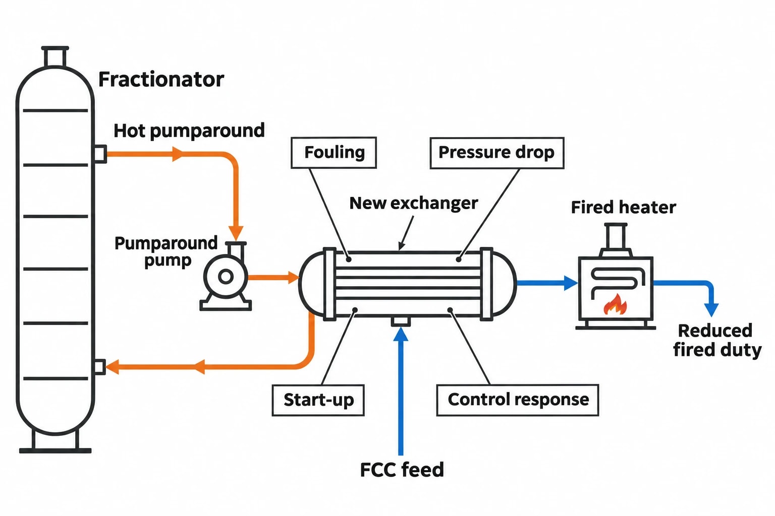
The best projects translate the pinch target into a shortlist of operable brownfield changes. These range from restoring lost exchanger performance to installing new surface area and rerouting process streams.
Feed preheat and heater fuel
Feed preheat is often the clearest route from recovered heat to lower fuel consumption. Raising feed temperature upstream of a fired heater reduces the duty required to reach the target coil-outlet temperature.
A pinch study can test whether FCC feed should receive heat from a different pumparound, a reactor-effluent exchanger, a slurry circuit or another refinery heat source. It also identifies whether an existing match consumes heat that would be more valuable at a higher temperature.
Design teams should assess heater inlet-temperature limits, feed stability, exchanger pressure drop, fouling propensity and start-up control. Heavy feeds, slurry services and cycle oils may require conservative fouling allowances, bypass arrangements and cleaning access.
Main-fractionator pumparound optimisation
Pumparounds link fractionator heat removal to refinery heat demand. Their flowrates, draw locations and return temperatures influence energy recovery and column operation.
A practical option may add an exchanger between a pumparound and feed. Another may reassign an existing exchanger so that a higher-temperature source serves a higher-value sink. Changes to pumparound flow or return temperature can also alter the available heat level.
Each option needs checks against fractionator hydraulics, product specifications, stripping performance and control response. An energy target has limited value if the revised arrangement causes unstable operation during throughput changes or feed transitions.
Steam-system integration
Steam demand can obscure the FCC heat balance. A unit may generate steam from recovered heat, import steam for stripping or reboiling, and reject condensate heat elsewhere in the refinery.
Pinch analysis identifies the pressure level at which heat recovery has value. Heat capable of raising low-pressure steam may not replace medium-pressure steam demand. Direct process-to-process heat recovery can avoid conversion losses where a stable, clean match exists. Steam generation may remain preferable where the site requires a dependable steam contribution or where direct recovery creates unacceptable fouling risk.
The assessment should show imported and exported steam by pressure level. Treating the steam system as a single undifferentiated utility produces unreliable savings estimates.

Pinch analysis identifies the thermodynamic minimum energy requirement of your process — then designs the heat exchanger network to achieve it.
From heat target to a brownfield FCC project
Ipieca indicates that pinch-analysis methodology can take one to three months, depending on plant simulation data and software compatibility. Implementing selected changes can take two to three years, depending on complexity and turnaround availability.
The difference reflects the gap between identifying an opportunity and modifying a live refinery unit.
Start with reconciled operating data
The study team should compare measured temperatures, flows and pressures with calculated exchanger duties. Inconsistent data should be resolved before setting targets.
Early checks should include:
- Actual exchanger duties against measured process conditions.
- Phase behaviour, including condensation, boiling and flashing.
- Separate stream data for normal operation, feed transitions and turndown.
- Realistic fouling resistance and pressure-drop margins.
- Exchanger bypass positions, leaking valves and flow maldistribution.
- Plot space, pipe-rack capacity and turnaround requirements.
The aim is to create a heat-recovery target that reflects expected operating conditions rather than an idealised design balance.
Rank measures by operability as well as energy
A feasible shortlist should compare fuel reduction, steam impact, cooling reduction, installed cost, turnaround dependency, inspection access and operational risk.
Existing exchangers may lack spare area. New surface can impose pressure-drop penalties. A preferred match may route a solids-bearing stream into an exchanger that cannot be cleaned effectively. Piping may require costly live-plant isolation work.
The refinery-wide guideline provides context for pinch-analysis opportunities but should not become the basis of an FCC project forecast. Expected savings from an individual FCC unit depend on its existing heat recovery, feed conditions, available heat sinks, utility system and retrofit constraints.
EU BAT and UK ESOS relevance
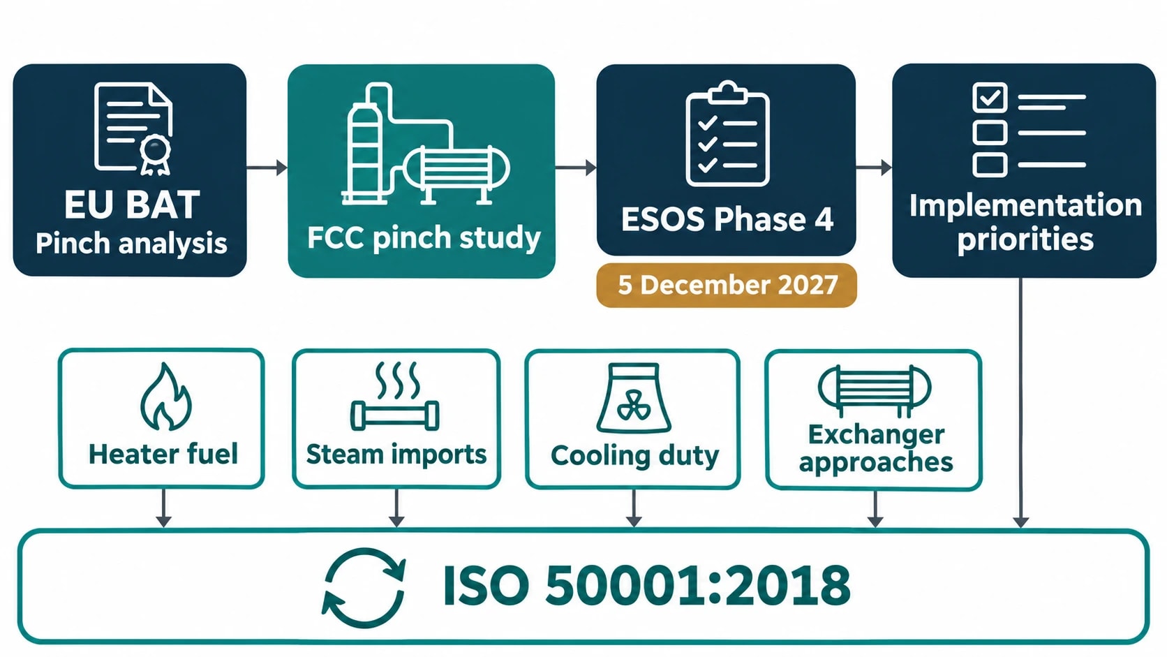
Commission Implementing Decision (EU) 2014/738 places pinch analysis within the energy-efficiency techniques available to EU mineral-oil and gas refineries under the Industrial Emissions Directive 2010/75/EU. The decision does not prescribe a fixed exchanger network. It establishes the relevance of systematic thermodynamic analysis when operators assess energy performance and improvement options.
For UK operators, the Energy Savings Opportunity Scheme applies to qualifying organisations and covers energy use in buildings, industrial processes and transport. The current Phase 4 guidance sets 5 December 2027 as the deadline for submitting a notification of compliance.
An FCC pinch study can strengthen the industrial-process element of an ESOS assessment by documenting energy consumption, identifying savings opportunities and providing a basis for implementation priorities. It can also support the evidence needed to explain how savings measures have been assessed and monitored.
ISO 50001:2018 provides a management framework for maintaining energy-performance improvements. A pinch target can provide an engineering benchmark, while heater fuel use, steam imports, cooling duty and exchanger approaches show whether the unit continues to achieve the intended result.
How to verify savings after implementation
Fuel consumption should be normalised for FCC throughput, feed properties, operating severity and product slate. A simple month-on-month comparison can misrepresent performance if the refinery has changed feed quality, conversion or operating rate.
A post-project monitoring plan should track:
- Fired-heater fuel per unit of FCC feed processed.
- Heater inlet temperature and relevant stack measurements.
- Imported and exported steam by pressure level.
- Main-fractionator pumparound temperatures and flowrates.
- Exchanger temperature approach, pressure drop and fouling trend.
- Cooling-water and air-cooler duty.
- Regenerator conditions that affect the FCC heat balance.
- CO₂ emissions associated with reduced fuel combustion.
The enduring benefit of fluid catalytic cracking unit pinch analysis is a documented operating envelope. It gives refinery teams a defensible heat-recovery target, a ranked list of modifications and indicators that reveal when fouling, altered feedstocks or changed operating practice erode performance.
This article reflects the independent analysis and editorial opinion of EnerTherm Engineering. Product names, trademarks, and brands mentioned belong to their respective owners. EnerTherm Engineering is not affiliated with, endorsed by, or a licensee of any third-party software or product mentioned unless explicitly stated.

Simulation Engineer — EnerTherm Engineering
Rajesh Sekar is a Simulation Engineer at EnerTherm Engineering, specialising in computational fluid dynamics (CFD), finite element analysis (FEA), and thermal process simulation. He holds a degree from Cranfield University and brings extensive experience in simulation-based product development from the automotive, aerospace, and energy sectors.
