How Pinch Technology Cuts CHP Fuel Use in UK Plants
Using the Process Grand Composite Curve to match CHP heat with plant demand
Pinch technology for cogeneration systems is a process-integration method that matches CHP heat and power output to a plant’s real heat demand at each temperature level. It cuts fuel use by reducing unnecessary steam generation and boiler firing.
Under the UK CHPQA scheme, annual power output qualifies fully as Good Quality CHP when the Quality Index reaches 100, while qualifying heat must demonstrably displace heat that would otherwise come from another source. Temperature matching is therefore central to a credible CHP case.
A gas engine, gas turbine or steam turbine can show strong combined efficiency at design conditions. Plant results depend on whether the process can absorb heat at the required temperature, pressure and time. A paper-machine dryer steam header, a food factory wash-water circuit and a pharmaceutical reactor train have very different thermal profiles. Annual gas and electricity totals conceal those differences.
Pinch Analysis brings the process, steam system and CHP plant into one study. It sets heat-recovery and utility targets before engineers select generating capacity, turbine extraction pressures or heat-recovery boiler duty. The CHP scheme is then sized around useful residual heat demand, reducing the risk of rejected heat and avoidable fuel consumption.
Why CHP fuel use rises without pinch technology
Many CHP studies begin with electrical load and seek a use for the heat that follows. This can produce a scheme whose thermal output exceeds the usable site load, particularly during reduced production, maintenance or warmer months.
A CHP unit may then operate at lower load, reject heat, bypass heat recovery or maintain a steam header above the process requirement. Each outcome weakens the boiler-fuel displacement that justified the project.
Heat demand has a temperature and time profile
A plant can have a large annual heat load while lacking a sufficient heat sink for a specific CHP output. Low-temperature engine jacket-water heat cannot replace medium-pressure process steam. High-pressure steam supplied to a low-temperature duty can also waste a pressure-drop opportunity that could generate power through a turbine.
Process engineers need a heat-demand picture that includes:
- Process-stream supply and target temperatures.
- Sensible heating, cooling, condensing and evaporation duties.
- Steam pressure and temperature requirements at each user.
- Batch, start-up, cleaning and shutdown patterns.
- Condensate return, flash steam and vent losses.
- Existing boiler, steam-turbine and CHP operating constraints.
This converts a CHP feasibility study from an annual balance into a process-integration exercise.
Pinch Analysis sets the minimum utility target
Pinch Analysis starts with site stream data. Each hot stream releases heat as it cools. Each cold stream requires heat as it warms. Engineers apply a practical minimum temperature approach that reflects exchanger area, fouling, pressure drop, cleanability, maintenance access and process safety.
Composite curves identify the maximum feasible process-to-process heat recovery and the minimum external hot-utility requirement. The pinch separates the site into two thermodynamic regions.
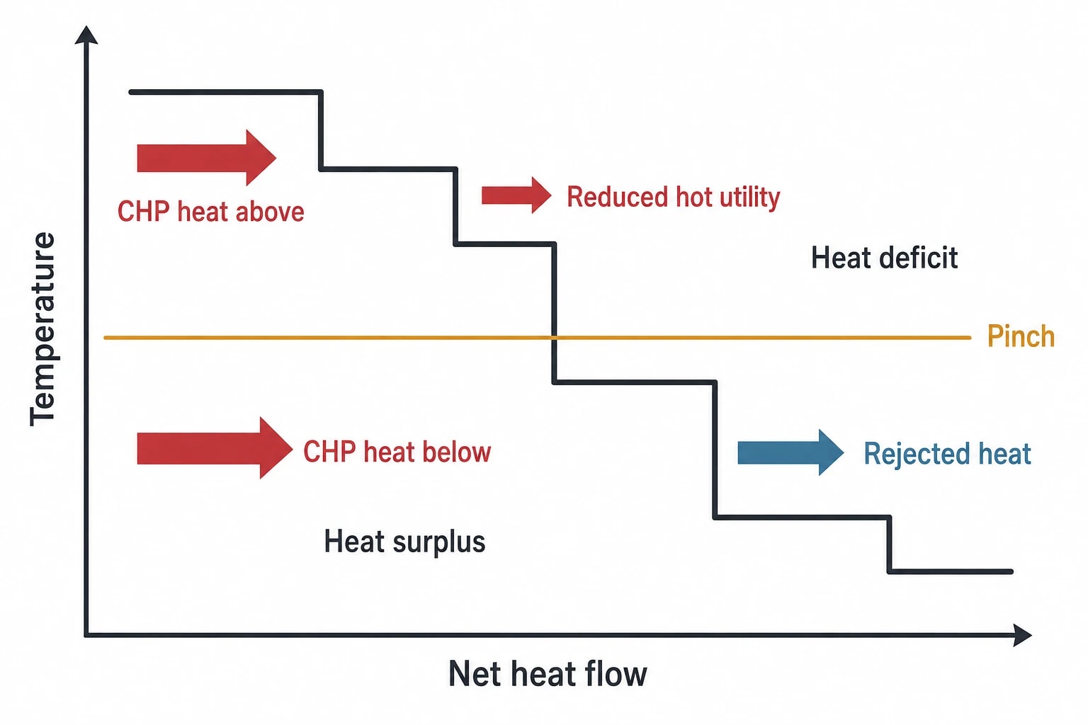
Above the pinch, the process has a heat deficit. CHP steam, exhaust recovery or boiler heat can supply it. Below the pinch, the process has a heat surplus and requires cooling or lower-temperature recovery.
The classic pinch rules remain decisive for CHP integration:
- Do not transfer heat across the pinch.
- Do not use external cooling above the pinch.
- Do not introduce external heating below the pinch.
A CHP heat source placed below the pinch displaces no minimum hot utility. It adds heat that must be rejected or forces another heat flow across the pinch. Fuel is then consumed without a corresponding reduction in process heat demand.

Pinch analysis identifies the thermodynamic minimum energy requirement of your process — then designs the heat exchanger network to achieve it.
Using the Process Grand Composite Curve for CHP heat recovery
The Process Grand Composite Curve, or PGCC, shows the site’s net heat deficit and surplus against shifted temperature. It reveals where the process needs heat after maximum internal recovery and where it has recoverable surplus.
For pinch technology for cogeneration systems, this is the most useful view of the site. A steam balance shows tonnes of steam; the PGCC shows whether steam at a given pressure can perform useful work.
Match CHP steam levels to the process deficit
Steam is both a heating medium and a route to power generation. High-pressure steam can expand through a back-pressure or extraction turbine before serving process users at a lower pressure. The PGCC helps identify how far that cascade can proceed without pushing heat into a temperature range where it cannot be used.
It can establish the viable split between:
| Utility level | Typical CHP integration question | Pinch target |
|---|---|---|
| High-pressure steam | Which duties genuinely need the highest temperature? | Limit supply to the remaining high-temperature deficit |
| Medium-pressure steam | Can turbine extraction serve process heating or reboilers? | Maximise useful extraction within the process heat sink |
| Low-pressure steam | Can lower-temperature users accept LP steam or recovered heat? | Avoid using higher-grade steam where LP steam is sufficient |
| Hot water or condensate | Can low-grade CHP heat displace fired heating? | Match heat recovery to continuous, suitable-temperature demand |
A proposed high-pressure header may prove unnecessary once process-to-process recovery and lower-pressure utility placement are considered. Conversely, the PGCC can confirm that a site has a durable high-temperature heat deficit that supports steam generation from gas-turbine exhaust.
Use utility pinches to avoid expensive steam placement
The PGCC can identify utility pinch points, where a steam utility level reaches the limit of feasible heat transfer to the process. These points guide how much low-pressure or medium-pressure steam the process can accept before a higher-grade utility becomes necessary.
If medium-pressure extraction satisfies a process deficit, supplying high-pressure steam directly creates a larger pressure drop than the duty requires. If low-pressure steam reaches a utility pinch, further LP supply will displace heat into a self-sufficient section of the process and provide no useful saving.
The resulting steam-level strategy is clear:
- Recover process heat wherever feasible.
- Supply the residual lower-temperature deficit with the lowest suitable utility level.
- Use higher-pressure steam only where the process temperature requires it.
- Select turbine extraction and exhaust-recovery conditions around those targeted loads.
This preserves the opportunity to generate electricity during pressure reduction while reducing fuel used for steam generation.
Treat exhaust recovery as a temperature-matched utility
Gas-turbine and reciprocating-engine exhaust carry heat across a broad temperature range. The total recoverable energy may appear attractive, yet a heat-recovery boiler can still produce steam that a site cannot use.
The PGCC tests the exhaust heat profile against the process deficit. It indicates whether the heat can support a heat-recovery steam generator, direct exhaust use, hot-water production or boiler-feedwater preheating. It also exposes heat available only below the site’s useful temperature threshold.
A heat-recovery package that lowers boiler firing produces a genuine fuel benefit. One that creates surplus low-pressure steam may increase condensate loads, heat rejection or operating restrictions without delivering the expected savings.
Pinch technology changes CHP sizing and configuration
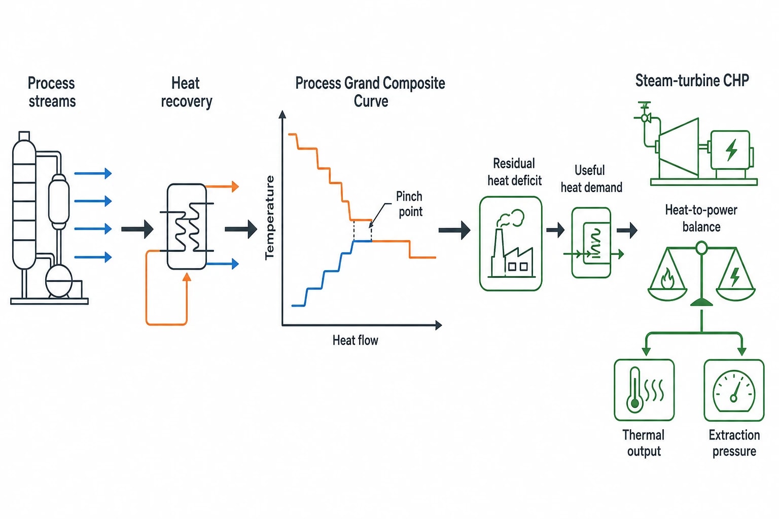
Pinch targets should precede equipment selection. A generator capacity chosen from electricity demand alone can impose a fixed heat output that the process cannot absorb. The CHP plant and heat-exchanger network must be assessed as one utility system.
Recover process heat before sizing the CHP plant
Existing plants often have avoidable steam demand caused by missed recovery between process streams. Hot product cooling, reactor cooling, condensate, dryer exhaust and hot effluent may offer heat for feed preheat, wash-water heating, boiler-feedwater heating or another process duty.
Recovering that heat reduces the minimum hot-utility target. The CHP scheme may then need a smaller thermal output, a different extraction pressure, a different operating schedule or a different prime-mover selection.
This avoids locking a factory into a CHP unit that appears viable only because recoverable process heat has been ignored. It also identifies cases where CHP remains attractive because a stable residual heat deficit persists after process recovery.
Design steam headers around real users
Steam headers often evolve over decades. New users are connected to existing pressure levels because the pipework is available, not because that level is thermally appropriate. Pinch targeting challenges these inherited arrangements.
For a steam-turbine CHP scheme, engineers can test whether:
- A higher-pressure header supports genuine process duties or merely feeds pressure-reducing valves.
- Medium-pressure extraction can replace live-steam let-down.
- Low-pressure users can accept reduced steam pressure without affecting product quality or throughput.
- Flash steam and condensate can cover part of the low-temperature demand.
- Steam exported from a heat-recovery steam generator has a useful load in all significant operating cases.
The answers establish the feasible heat-to-power balance before turbine design. They also help define control arrangements that maintain header pressure without venting steam or routinely using a pressure-reducing valve to balance the system.
Test part-load and seasonal operation
A CHP system must work beyond the design-point heat balance. Batch sites may see sharp but short-lived steam peaks. Food and beverage sites can have cleaning cycles that differ from production demand. Paper mills can experience changing dryer loads with grade and production rate.
The pinch model should test representative operating cases, including normal, minimum and maximum production. It should also include CHP outage conditions, boiler standby requirements, summer heat demand and anticipated process changes.
A project that relies on an annual average can overstate useful heat. CHPQA Guidance Note 50 expects evidence that claimed useful heat corresponds to a real, economically justifiable demand and does not exceed the heat otherwise required. Historic fuel data, metered heat profiles and production data provide stronger evidence than a single annual consumption figure.

Pinch analysis identifies the thermodynamic minimum energy requirement of your process — then designs the heat exchanger network to achieve it.
A practical workflow for pinch analysis for CHP heat recovery
A disciplined study reduces the chance that later design work reverses the energy target. Early stages should be based on operating evidence, then refined with equipment constraints and control requirements.
Build a reliable site dataset
Initial data collection should include process streams, utility flows and CHP heat sources. For each material stream, record flow, supply temperature, target temperature, heat-capacity flowrate, phase change and operating duration. For utility systems, capture steam generation, header pressures, condensate return, boiler-feedwater conditions, blowdown, flash recovery and venting.
Metered data should be reconciled against gas consumption, boiler output, electricity generation and site production. Large gaps in a heat balance commonly point to unmeasured condensate losses, bypassed exchangers, inaccurate steam-flow measurement or changing operating practice.
Set targets before heat-exchanger-network design
The targeting stage should define:
- Minimum hot and cold utility demand after feasible heat recovery.
- Pinch temperature and the heat deficit above it.
- Utility-pinch constraints for high-, medium- and low-pressure steam.
- CHP heat-recovery opportunities at each temperature level.
- Heat-rejection risk at low process demand.
- Fuel and carbon effects for normal and part-load CHP operation.
Only after these targets are established should the team select exchanger duties and physical locations. A feasible thermal match can still fail because of fouling, contamination, clean-in-place requirements, pressure loss, insufficient plot space or poor controllability. These constraints should shape the selected minimum temperature approach and the resulting network design.
CHPQA and UK environmental permitting
Pinch Analysis does not replace CHPQA assessment or permit work. It provides evidence that claimed heat is useful, the site has a viable heat sink and the proposed utility arrangement reduces fuel use.
CHPQA Good Quality CHP criteria
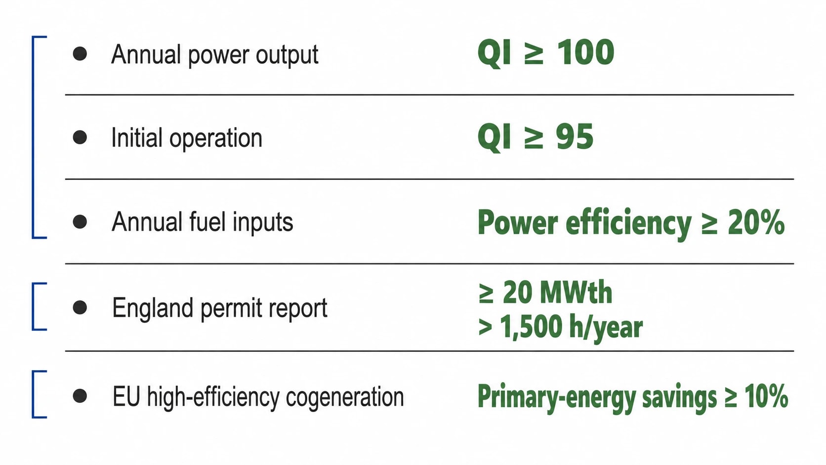
The CHPQA Standard applies across the UK. CHPQA Guidance Note 10 states that a scheme qualifies fully for Good Quality CHP on annual power output when its Quality Index is at least 100. During initial operation, the threshold is 95. A scheme qualifies fully for annual fuel inputs when power efficiency is at least 20%.
The Quality Index accounts for both power and qualifying heat. Qualifying heat is demonstrably used to displace heat that would otherwise be supplied from another source. Heat rejected through condensers, radiators, chimneys or exhausts does not meet that definition.
A PGCC and associated operating cases provide a sound technical basis for this evidence. They show the process temperature requirement, the available CHP heat source and the limits on useful supply at each utility level.
Environmental permits and waste-heat assessment
In England, Environment Agency guidance for medium combustion plants refers to Schedule 24 of the Environmental Permitting Regulations for plants with a total thermal rated input of 20 MWth or more that produce waste heat at a useful temperature.
A new or substantially refurbished in-scope boiler, furnace, gas turbine or compression-ignition engine operating more than 1,500 hours per year requires an energy-efficiency report. The threshold concerns aggregated net thermal input, so multiple combustion units on one site can matter.
A pinch study strengthens the heat-recovery evidence in such a report. It can document the proposed heat source, process heat sinks, temperature levels, annual operating periods, steam-system effects and any remaining recovery limitation.
EU high-efficiency cogeneration benchmark
Directive (EU) 2023/1791 Annex III defines high-efficiency cogeneration as cogeneration production achieving primary-energy savings of at least 10% compared with harmonised references for separate heat and electricity production. The Directive includes separate treatment for small-scale and micro-cogeneration.
For UK manufacturers with EU operations, group reporting requirements or projects in EU jurisdictions, this benchmark reinforces the same discipline. The comparison depends on actual useful heat and power performance. Heat that cannot displace another source does not support the primary-energy-saving case.
Where UK plants can find the strongest CHP fuel reductions
The strongest opportunities often sit between established responsibilities: the process team owns heat demand, utilities personnel own steam headers, maintenance owns exchangers and energy managers own the CHP business case. Pinch technology gives these decisions a shared temperature-based target.
A chemical site may recover process heat into boiler feedwater and reserve medium-pressure steam for duties that need it. A paper mill may revise dryer steam pressure, flash-steam recovery and condensate handling before choosing extraction conditions. A food manufacturer may build its CHP heat sink around continuous process-water demand instead of intermittent cleaning peaks.
Process heat recovery comes first. CHP supplies the residual deficit at the appropriate temperature level. Steam pressure reduction is used where it can generate power while meeting process demand.
This article reflects the independent analysis and editorial opinion of EnerTherm Engineering. Product names, trademarks, and brands mentioned belong to their respective owners. EnerTherm Engineering is not affiliated with, endorsed by, or a licensee of any third-party software or product mentioned unless explicitly stated.

Managing Director — EnerTherm Engineering
Dr. François Pierrel is Managing Director of EnerTherm Engineering with over two decades of expertise in thermal design, heat transfer, and industrial energy optimisation. He holds a PhD in Heat Transfer from Cranfield University and a Post-Doctorate from Heriot-Watt University.
