Why the Organic Rankine Cycle Pinch Point Sets Power Output
A model case using 20 K and 5 K pinches to assess heat recovery
An organic Rankine cycle pinch point is the smallest local temperature difference between a waste-heat stream and the ORC working fluid in the evaporator, or between the working fluid and cooling medium in the condenser. It determines the heat duty that can cross each heat exchanger, the temperatures at which the cycle evaporates and condenses, and the electrical output available after auxiliary loads.
A waste-heat source can look attractive on a site heat balance yet yield modest power. A paper mill may have warm condensate, a food factory may reject refrigeration heat, and a waste-to-energy plant may have a hot gas stream. The ORC cannot cool these streams below the temperature allowed by its working-fluid profile and selected minimum approach temperature.
The organic Rankine cycle pinch point belongs at the centre of feasibility work. It links thermodynamics to heat-exchanger area, source outlet temperature, expander duty, cooling conditions and annual generation. A higher evaporation temperature may improve cycle efficiency yet reduce heat recovered from a finite waste-heat stream. The result can be lower net power.
What an organic rankine cycle pinch point means
An ORC uses an organic working fluid rather than water to convert heat into mechanical work and electricity. A pump raises the liquid pressure. The working fluid passes through a preheater and evaporator, and sometimes a superheater, before entering an expander. The vapour expands to produce shaft power. A condenser rejects heat to cooling water, air or another heat sink before the pump repeats the cycle.
The temperature difference between the two streams is not constant through either main heat exchanger. It changes with heat capacity, phase change, pressure drop and flow arrangement. The lowest local difference is the pinch point.
A feasible design keeps a positive temperature driving force at all locations. The selected minimum pinch-point temperature difference also requires sufficient heat-transfer surface to sustain that approach in clean and fouled service.
Evaporator pinch point
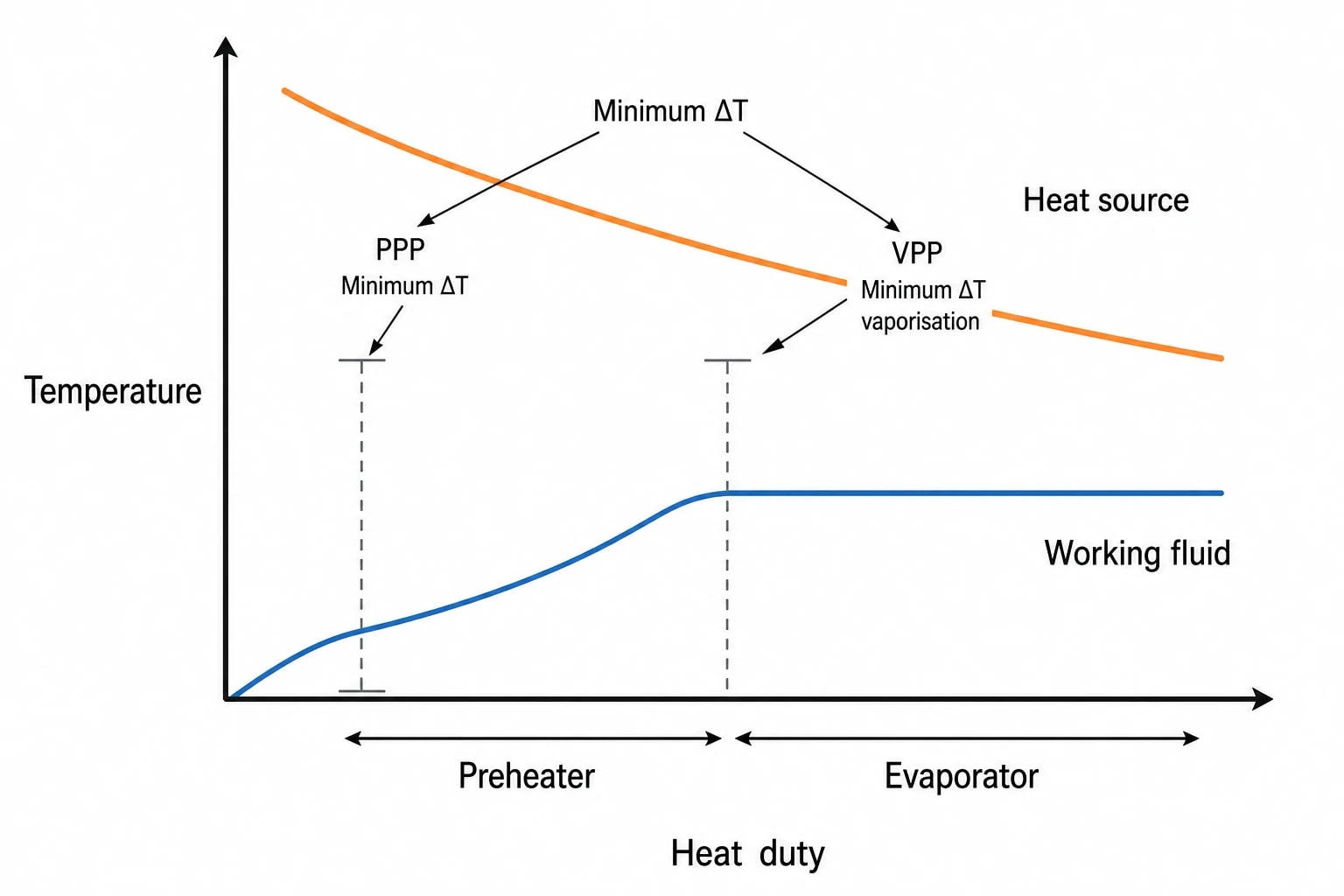
In a subcritical ORC evaporator, the working fluid usually heats sensibly in the preheater and then evaporates at an approximately constant saturation temperature. The source stream cools continuously. Their temperature profiles can approach closely at different locations.
For a finite source stream, the evaporator pinch point limits the final source outlet temperature. A tighter pinch permits deeper source cooling and can increase heat absorbed by the cycle. More absorbed heat can support greater working-fluid mass flow and more vapour flow through the expander.
The gain depends on the complete source profile. A hot thermal-oil circuit and a low-pressure steam-condensate stream do not impose the same pinch constraint, even if their inlet temperatures match.
Preheating pinch point and vaporisation pinch point
Engineers must identify the evaporator pinch point rather than assume it sits at the start of evaporation.
Two established locations matter in an ORC without superheat:
- The preheating pinch point, or PPP, occurs at the start of working-fluid preheating.
- The vaporisation pinch point, or VPP, occurs at the start of vaporisation, where the fluid reaches its saturation temperature.
Haoshui Yu and Xiao Feng described these locations in their 2014 paper, Pinch Position Between Heat Carrier and Working Fluid in Organic Rankine Cycle for Waste Heat Recovery, published in Chemical Engineering Transactions. Haoshui Yu, Xiao Feng and Yufei Wang subsequently used PPP and VPP in their 2015 Energy paper, A New Pinch Based Method for Simultaneous Selection of Working Fluid and Operating Conditions in an ORC Recovering Waste Heat.
The distinction changes the result of optimisation. Heat-capacity flow rate on the waste-heat side, source inlet temperature, evaporation temperature and the ratio of latent to sensible heat all affect where the closest approach occurs. A calculation that checks only the VPP can overstate recoverable heat when the real constraint lies at the cold end of the preheater.
Condenser pinch point
The condenser pinch point is the smallest temperature difference between condensing working fluid and the cooling medium. With cooling water, it commonly occurs at the warm end of the water path. With an air-cooled condenser, ambient dry-bulb temperature, fan performance and recirculation of warm discharge air can govern the available approach.
A lower condenser pinch can support a lower condensing temperature and pressure. This increases the enthalpy drop available across the expander and can improve gross power. It also demands more condenser surface, more cooling flow, or both.
For air-cooled ORCs, the summer design condition often has greater commercial importance than the cool-weather output figure. It determines condenser pressure when the plant needs the most fan power and has the least temperature difference available for heat rejection.

Pinch analysis identifies the thermodynamic minimum energy requirement of your process — then designs the heat exchanger network to achieve it.
Why a smaller pinch point can raise ORC power output
The organic Rankine cycle pinch point affects power through two routes: heat absorbed in the evaporator and work available from expansion.
A smaller evaporator pinch allows closer thermal matching between the source and working fluid. Given sufficient heat-exchanger area, the source can leave cooler. The ORC receives more heat and may circulate more working fluid, increasing the mass passing through the expander.
A smaller condenser pinch allows a lower condensing temperature. The expander then discharges against a lower back-pressure. Each kilogram of vapour can deliver more work, subject to fluid properties and expander efficiency.
Neither relationship is linear. The final few kelvin of approach require disproportionately more heat-transfer surface because the local temperature driving force becomes small.
Heat-exchanger area versus additional generation
James Bull, James M. Buick and Jovana Radulovic set a 20 K evaporator pinch point and a 5 K condenser pinch point in their 2020 Energies study, Heat Exchanger Sizing for Organic Rankine Cycle. Their model used R1234yf, hot water at 150 °C and chilled water at 5 °C. These figures are useful sensitivity-case inputs, not universal ORC design rules.
The appropriate pinch-point temperature difference depends on the source, sink and heat-exchanger duty.
| Design choice | Likely effect on power | Main engineering consequence |
|---|---|---|
| Smaller evaporator pinch | More source cooling and potentially higher vapour flow | More evaporator area and possible source-side pressure drop |
| Smaller condenser pinch | Lower condensing pressure and potentially more expander work | More condenser area, cooling flow or fan duty |
| Higher evaporation temperature | Can improve specific work and thermal efficiency | May restrict source cooling and reduce recovered heat |
| Greater working-fluid flow | Can increase gross output | Larger pump, pipework, expander capacity and pressure losses |
| Higher cooling-medium flow | Can lower condensing temperature | Higher pump or fan electricity use |
The commercial optimum is where the value of additional annual net generation exceeds the cost of extra surface area, associated auxiliaries and maintenance.
Gross power is not the project output
A narrow pinch point can increase gross generator output while reducing the benefit at the electrical connection point. Cooling-water pumps, air-cooled condenser fans and working-fluid pumps consume power. Pressure drop also has a direct thermodynamic cost.
An ORC evaluation should compare net output at each design point and deduct:
- Working-fluid pump electricity.
- Cooling-water pumping electricity.
- Air-cooled condenser fan electricity.
- Source-side pumping or fan penalties caused by heat-exchanger pressure drop.
- Part-load losses during low source temperature or flow.
This matters particularly for low-grade heat. A few kilowatts of extra fan power can materially change the value of a small ORC installation.
How evaporation temperature changes recoverable heat
Evaporation temperature often dominates early ORC design discussions because it influences efficiency and expander inlet conditions. It cannot be selected independently from the evaporator pinch point.
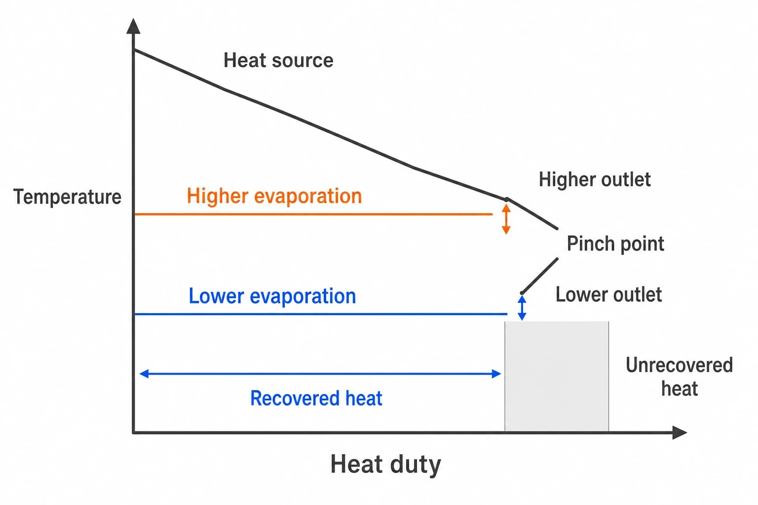
A higher evaporation temperature raises the working-fluid saturation temperature. The waste-heat stream must remain above that saturation temperature plus the required pinch. Its outlet temperature rises, leaving less heat available to the ORC.
A lower evaporation temperature can cool the same source further and capture more heat. The vapour then reaches the expander at lower pressure and temperature, reducing work available per kilogram of working fluid. The best point depends on the balance between heat duty and conversion efficiency.
Yu, Feng and Wang’s 2015 Energy paper found that increasing evaporation temperature can improve cycle efficiency while reducing recovered heat once pinch constraints limit source cooling. Net power may therefore fall despite higher efficiency.
A practical source-temperature example
Consider an industrial liquid stream with a fixed inlet temperature and a required minimum approach at the VPP. Raising ORC evaporation temperature moves the working-fluid evaporation line upwards. The source outlet must also move upwards to retain the selected pinch. The unrecovered heat remains in the process stream.
A cycle calculation based only on thermal efficiency misses that heat-duty reduction. A heat-exchanger calculation based only on available duty misses the change in expander work. The project model needs both.
Source conditions that determine the answer
The design case must represent the heat source that exists at the plant boundary. Key inputs include:
- Minimum, normal and maximum source inlet temperatures.
- Source-flow range over production cycles and plant turndown.
- Required source outlet temperature for process stability.
- Permitted source-side pressure drop.
- Stream composition and fouling mechanisms.
- Heat availability by operating hour, rather than annual average heat duty.
- Cooling conditions through summer and winter.
Flue gas requires a separate source outlet limit. Cooling it too far can create condensation and corrosion risks that depend on fuel chemistry and downstream equipment. That limit can be substantially warmer than the temperature that would maximise ORC heat recovery in a theoretical model.
Pinch-point migration matters during fluctuating operation
The evaporator pinch point can move from the PPP to the VPP, or in the opposite direction, as source flow, source temperature, evaporation pressure and working-fluid circulation rate change.
This is common at industrial sites with batch production, variable dryer loads, incinerator load changes or seasonal cooling conditions. The ORC may meet its design pinch at one point in the heat exchanger during steady operation, then approach a different constraint during a rapid source change.
Control must protect the real limiting location
One approach-temperature measurement cannot reliably describe every operating condition. Instrumentation should cover relevant hot- and cold-side inlet and outlet temperatures. The control philosophy should assess the active pinch location across the expected operating envelope.
Control objectives normally include:
- Preventing a temperature cross in the evaporator.
- Maintaining stable evaporation pressure and expander inlet condition.
- Avoiding excessive source-side pressure drop.
- Holding condenser pressure within expander and working-fluid limits.
- Reducing output in an orderly way when source temperature falls.
A model should test the minimum source-temperature and flow combination, not only the nameplate point. That condition may set the practical minimum load and identify whether a bypass, thermal buffer or variable working-fluid circulation strategy is needed.
Annual output needs time-resolved data
A single steady-state point can provide useful first-pass sizing, but it cannot establish annual generation for a fluctuating source. Process engineers should use historian data where available, then calculate ORC performance across representative source and cooling cases.
A weighted set of operating cases can be sufficient if the source follows repeatable production states. Higher-resolution data becomes more valuable where temperature and flow vary sharply, or where the plant spends significant time close to the evaporator pinch constraint.
The output should show annual gross generation, annual auxiliary consumption and annual net generation. It should also state the hours when the ORC cannot operate at full load because the source falls below its viable approach temperature.

Pinch analysis identifies the thermodynamic minimum energy requirement of your process — then designs the heat exchanger network to achieve it.
Working-fluid selection follows the temperature match
Working-fluid selection and pinch analysis are the same design problem viewed from different directions. The fluid determines saturation pressure, critical temperature, latent heat, heat capacity, expansion behaviour and thermal stability. These properties set the working-fluid temperature profile in the evaporator and condenser.
A fluid with a favourable profile can match the waste-heat source more closely within the same heat-exchanger footprint. Another fluid may leave a large temperature difference across much of the heat exchanger while creating one restrictive pinch point.
What to compare during fluid screening
A credible screening exercise compares candidate fluids against measured source and cooling profiles. It should examine:
- Feasible evaporation and condensation pressures.
- Critical temperature relative to the maximum source temperature.
- PPP and VPP location at each operating case.
- Expander inlet state and expansion behaviour.
- Condenser duty and achievable condensing temperature.
- Thermal stability at the highest anticipated fluid temperature.
- Compatibility with seals, lubricants and heat-exchanger materials.
- Safety and environmental requirements applicable to the site.
Near-critical evaporation can offer a closer thermal match for certain source profiles. It also changes fluid properties and heat-transfer behaviour rapidly near the critical region. A design that produces the highest output at one source condition may offer less stable operation across the plant’s actual range.
Heat-exchanger design turns the pinch target into reality
The stated pinch point must remain achievable after installation. Heat-transfer coefficients, fouling allowance, flow distribution and pressure drop determine whether the heat exchanger can meet its promised approach temperature.
Bull, Buick and Radulovic compared plate and shell-and-tube heat exchangers across ORC preheater, evaporator, superheater, precooler and condenser duties. In their specific R1234yf case, the plate heat-exchanger arrangement required less area than the shell-and-tube arrangement. That comparison does not establish a universal preference.
Plate heat exchangers can suit clean services where compactness and high heat-transfer coefficients are valuable. Shell-and-tube heat exchangers can suit duties requiring mechanical cleaning, specific pressure capability or greater tolerance of dirty streams. The source stream, working-fluid pressure, maintainability and inspection requirements should determine the selection.
Fouling consumes pinch margin
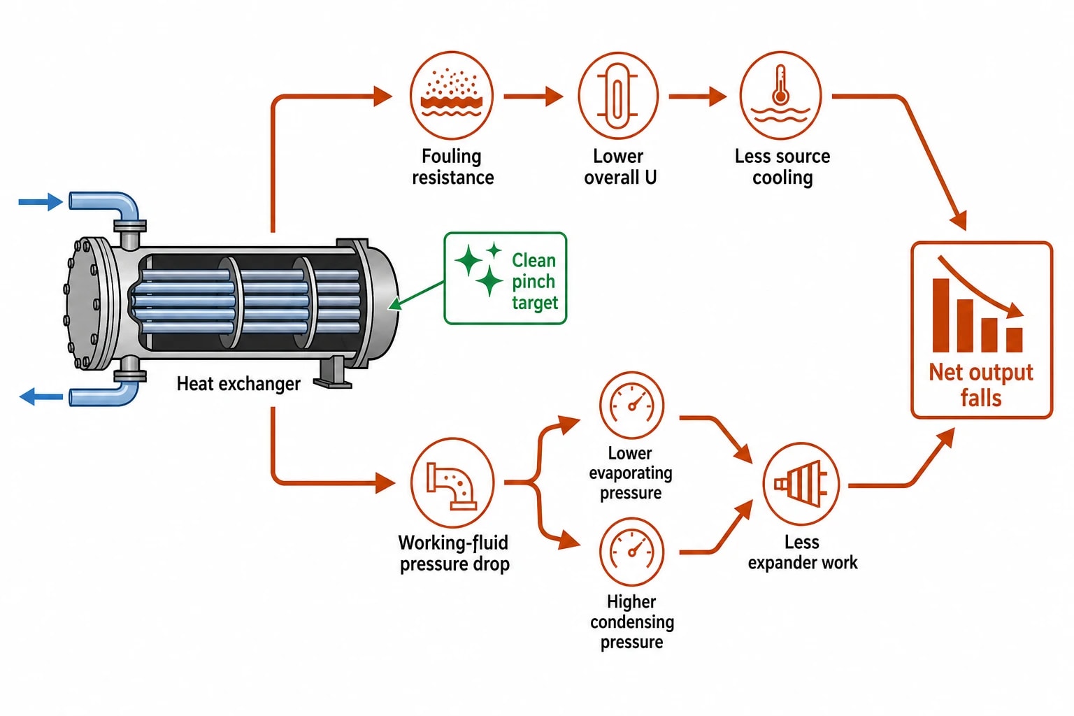
Fouling lowers the overall heat-transfer coefficient. A design with a narrow clean pinch can then lose source cooling, operate at higher condensing pressure, or both. Net output falls.
Food and beverage, paper and waste-to-energy streams present different fouling mechanisms. The design must use realistic fouling resistance and include access for cleaning. A feasibility model that assumes permanently clean surface area will overstate long-term generation.
Pressure drop can erase the benefit
Pressure drop on the working-fluid side reduces evaporating pressure or increases condensing pressure. Both reduce expander work. Pressure drop on the source side can impair process operation or increase pumping demand.
The pinch-point target, heat-transfer area and pressure-drop allowance must be optimised together. A larger heat exchanger often allows a tighter approach at lower velocity, but physical footprint, cost and maintainability still set practical limits.
A pinch-analysis workflow for industrial ORC projects
An ORC should be treated as part of the site heat-recovery network. The following workflow keeps the organic Rankine cycle pinch point tied to plant operation and project value.
-
Characterise the source using measured temperature, flow, operating hours, contamination risk and process outlet constraints.
-
Define cooling conditions, including seasonal ambient data, cooling-water temperature, flow limits and auxiliary power.
-
Build hot and cold temperature profiles for candidate working fluids and operating pressures.
-
Check both PPP and VPP in the evaporator, then identify the active pinch across the operating range.
-
Vary evaporator pinch point, condenser pinch point, heat-exchanger area and pressure-drop allowances together.
-
Calculate gross output and deduct all auxiliary loads to obtain net power.
-
Use time-resolved or weighted operating cases to calculate annual generation.
-
Set performance guarantees around real source conditions, defined pinch points, fouling assumptions, cooling design condition and net electrical output.
The best ORC design does not necessarily use the smallest feasible pinch point. It uses evaporator and condenser approaches that capture sufficient additional waste heat, at workable evaporation and condensing temperatures, to deliver the highest credible annual net generation from the industrial source.
This article reflects the independent analysis and editorial opinion of EnerTherm Engineering. Product names, trademarks, and brands mentioned belong to their respective owners. EnerTherm Engineering is not affiliated with, endorsed by, or a licensee of any third-party software or product mentioned unless explicitly stated.

Managing Director — EnerTherm Engineering
Dr. François Pierrel is Managing Director of EnerTherm Engineering with over two decades of expertise in thermal design, heat transfer, and industrial energy optimisation. He holds a PhD in Heat Transfer from Cranfield University and a Post-Doctorate from Heriot-Watt University.
