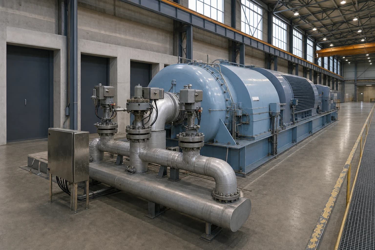
Steam Header Reconciliation Exposes Turbine and PRV Losses
A mill-wide method for tracing turbine extractions, PRVs and condensate returns
Steam header reconciliation is the disciplined calculation and validation of every steam, condensate, water and energy flow entering, leaving and moving between a mill’s multi-pressure steam headers.
A kraft or integrated pulp and paper mill can show stable header pressures while its heat and mass balance remains wrong. A pressure-reducing valve may pass substantial live steam into a lower-pressure header while a back-pressure turbine operates below its available extraction capacity. A condensate return can appear healthy in the control room yet exclude flash steam, drains or a failed level-based estimate. These gaps conceal fuel use, lost generation and operating constraints.
The engineering task is to turn scattered measurements into one defensible account of the utility system. That account must cover recovery boiler steam, power boiler steam, turbine admissions and extractions, pressure-reducing valve stations, paper-machine demand, evaporators, deaerators, blowdown, flash vessels and condensate returns. It must also reflect the operating state in which the measurements were taken.
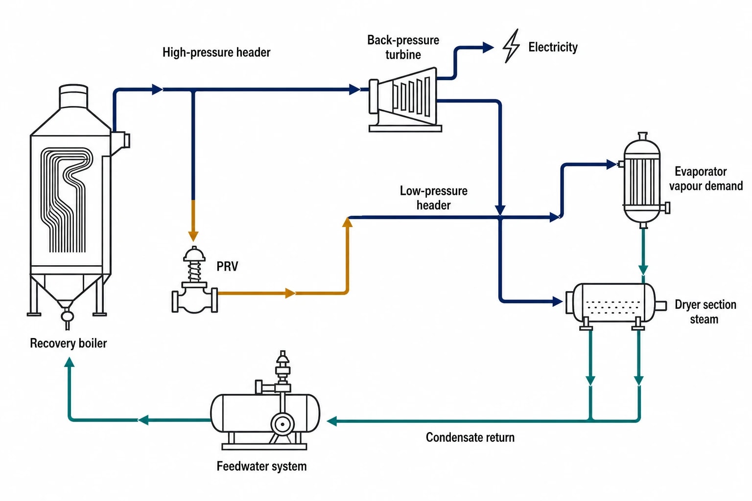
For pulp and paper sites, this is not a utility exercise at the edge of the process. Steam and condensate links connect recovery operations, evaporation, drying, power generation and boiler-feedwater quality. A reconciled model identifies where a tonne of steam changed pressure, where its available work was bypassed, and whether the returning water closes the loop.
Why steam header reconciliation matters in pulp and paper
Stable pressure does not prove efficient operation
Header pressure control protects production. It does not quantify the best allocation of steam between turbines, PRVs and consumers.
A low-pressure header can hold its pressure because a PRV opens whenever demand rises. That response may be correct for process stability, turbine maintenance or a short-lived upset. It can also conceal a persistent pattern in which high-pressure steam bypasses a turbine that could otherwise generate electricity while supplying the same process header.
Steam header reconciliation separates those situations. It combines flow, pressure, temperature, electrical output and condensate data into one balance, then tests whether the resulting account is physically credible.
The European Commission’s pulp-and-paper BAT Conclusions, adopted through Commission Implementing Decision 2014/687/EU under the Industrial Emissions Directive 2010/75/EU, provide a useful frame. BAT 31 and BAT 38 call for combinations of energy-reduction measures that include high-efficiency steam boilers, effective secondary heating, appropriate use of secondary condensate, monitoring and control, and optimisation of integrated heat-exchanger networks. The decision also identifies high recovery-boiler pressure and temperature, low technically feasible back-pressure turbine outlet pressure, and high turbine efficiency as power-generation measures.
A header model provides the evidence needed to judge where those measures fit. It links boiler performance to the actual destination and pressure level of the steam produced.
The balance must extend beyond the turbine house
The European Commission’s 2015 Pulp, Paper and Board BREF, EUR 27235, covers integrated and non-integrated pulp and paper production, including kraft processes, energy consumption, water use and recovery operations. A turbine extraction cannot be assessed in isolation from evaporator vapour demand, dryer-section steam pressure, secondary-condensate use and the feedwater system.
A mill-wide reconciliation starts at the energy sources and ends at the water returned to the boilers. It treats the steam system as a connected process network, rather than a collection of separate headers.

Map every energy and material flow in your process with detailed heat and mass balance calculations — the foundation for any optimisation or design project.
What a multi-pressure steam header balance must include
Define real boundaries and operating cases
The first decision is the time basis. A one-hour snapshot during a grade change or recovery-boiler instability can produce a misleading result. Use a period in which the mill was sufficiently steady, then repeat the work for the operating cases that matter:
- Normal production at representative grade and throughput
- High dryer load or wet-end upset
- Recovery boiler constraint
- Turbine limited or unavailable
- Winter heating load
- Summer minimum steam demand
- Planned PRV or turbine-bypass operation
The model should distinguish measured values from calculated values and fixed design information. It should record timestamp alignment, pressure basis, instrument range, calibration status and the source of each value. A flow total from a historian, an operator round and a calculation based on valve position do not carry equal weight.
Build a single-source-of-truth PFD
A reconciled process flow diagram should show each header at its operating pressure, not merely its nominal design name. It should identify every source, sink, cross-tie and loss path.
At minimum, include:
- Recovery boiler, power boiler and package-boiler main steam
- Turbine admission, controlled and uncontrolled extractions, exhaust, and condenser flows
- PRV stations, warm-up lines, bypasses and desuperheating water
- Process consumers such as evaporators, digester heating, dryer sections, air heaters and deaerators
- Flash vessels, flash-steam headers, vents and vents routed to recovery
- Condensate receivers, pumps, polishing, return headers, boiler-feedwater make-up and blowdown
- Drains entering condensate recovery, sewer or atmosphere
Each stream table should contain mass flow, pressure, temperature where meaningful, phase or steam condition, enthalpy, data source and confidence level. Enthalpy converts a flow diagram into an energy account. Two lines with the same steam mass flow can carry materially different energy if their pressure or degree of superheat differs.
Treat condensate as a measured utility stream
Condensate is often the weakest part of a steam balance and where considerable error accumulates.
A condensate flow returning from a paper-machine dryer group may differ from the steam admitted because of flash-steam recovery, vents, drain losses, seal leakage, held-up inventory and unmeasured process uses. A receiver level trend indicates changing inventory, not a direct measure of return flow. A reconciliation should account for inventory changes or select a period in which they are negligible.
The water balance should include boiler feedwater, make-up water, boiler blowdown, condensate return, flash-steam generation and liquid discharge. A consistent condensate account helps engineers distinguish a genuine steam loss from a measurement issue at the consuming equipment.
How turbine and PRV losses become visible
PRV flow identifies an opportunity, not an automatic fault
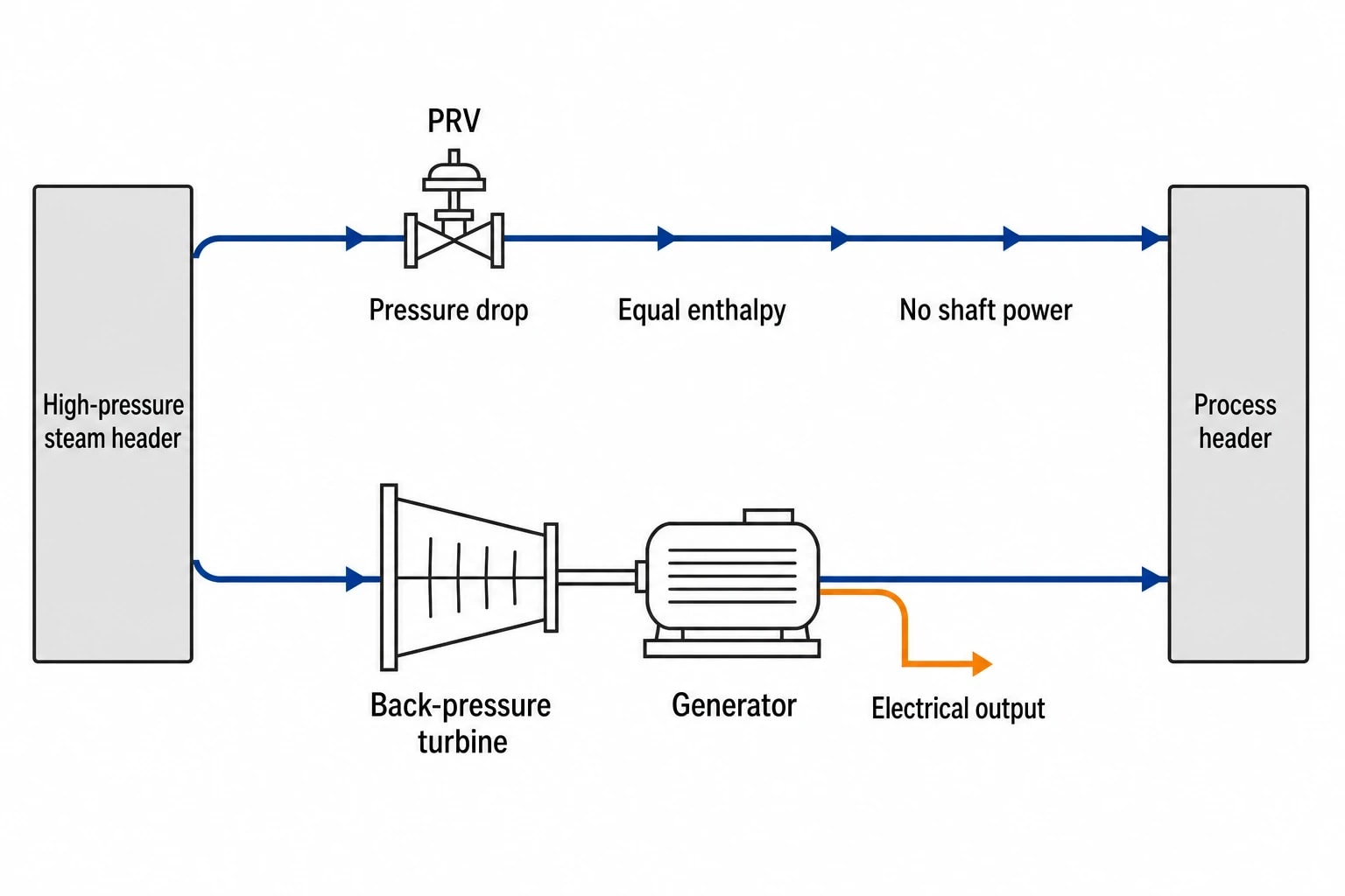
A pressure-reducing valve performs a necessary control function. It lowers steam pressure to meet process demand and absorbs rapid changes that a turbine or extraction-control system may not manage alone. The engineering value lies in quantifying how often and how much it does this.
For a throttling PRV at steady conditions, inlet and outlet enthalpy are generally treated as equal. The valve reduces pressure without producing shaft power. If a turbine can take that same pressure drop and its exhaust serves a useful process header, part of the steam’s available work can become electricity.
The reconciliation should report PRV flow by station and operating case, alongside:
- Upstream and downstream pressure
- Steam temperature and condition at the inlet
- Duration and load profile
- Parallel turbine capacity and actual extraction
- Turbine generator output
- Process header pressure requirement
- Bypass and trip events
- Whether the lower-pressure steam had a confirmed useful destination
A high average PRV flow is an investigative signal. A turbine may be at a valid mechanical limit, the header may require rapid pressure support, or lower-pressure demand may exceed the practical extraction range. The model should identify the reason before an operating change or capital project is proposed.
Turbine losses require a different test
A turbine lowers steam enthalpy while converting part of that energy into shaft work and then electrical output. Reconciliation exposes a problem when the measured admission, extraction and exhaust conditions do not support the measured electrical result, after allowing for the operating configuration and measurement uncertainty.
Useful checks include comparison with a commissioning curve or vendor performance information at comparable steam conditions, load and extraction arrangement. The review should identify whether the turbine has operated with partial admission, throttle governing, high exhaust pressure, extraction limits or significant bypass flow.
Common findings include:
- PRV letdown operating in parallel with an underloaded back-pressure turbine
- Turbine extraction pressure set above the process requirement
- Excessive exhaust or extraction pressure caused by downstream restrictions
- Turbine bypass left open after commissioning, maintenance or an upset
- High-pressure steam supplied to a low-pressure consumer through an undocumented cross-tie
- Extraction flow inferred from an unreliable differential-pressure measurement
- Turbine output compared across non-comparable steam flow and pressure conditions
The balance cannot diagnose blade-path condition by itself. It establishes the measurement-backed performance case that determines whether a detailed turbine test, control review or mechanical inspection is justified.
Value the loss at the correct boundary
A PRV does not destroy steam mass. It dissipates a pressure drop that might have produced electrical work in a back-pressure turbine. The economic value of that missed generation depends on the plant’s fuel cost, boiler constraints, marginal electricity value, turbine efficiency, process heat requirement and operating duration.
The same discipline applies to a turbine shortfall. Do not convert an apparent electrical gap directly into boiler fuel without checking whether the turbine exhaust still delivered process heat, whether another boiler increased firing, and whether site export or import changed. A complete heat and mass balance assigns the energy consequence to the relevant fuel, power and process boundaries.

Map every energy and material flow in your process with detailed heat and mass balance calculations — the foundation for any optimisation or design project.
A practical reconciliation workflow for mill teams
Start with plant evidence, then reconcile the model
EnerTherm Engineering’s 11-step heat and mass balance methodology provides a useful structure for this work. It begins with plant evidence such as P&IDs, operating logs, historian trends, laboratory data and targeted field measurements. The final deliverable is a single-source-of-truth PFD with embedded stream tables and a validated mass and energy balance.
For steam headers, the core sequence is straightforward:
- Freeze the PFD topology and identify all live-steam, condensate, flash and water boundaries.
- Select representative steady operating periods and retain upset cases as separate models.
- Collect flow, pressure, temperature and electricity measurements on a common time basis.
- Check transmitter ranges, flow-meter configuration, pressure basis and data plausibility.
- Calculate steam properties consistently from the selected thermodynamic property method.
- Reconcile the mass and energy balances within stated measurement uncertainty.
- Investigate the largest residuals in the field before treating them as losses.
- Rank confirmed opportunities by energy effect, production risk, safety impact and implementation route.
Process integration teams often use Aspen Plus, Aspen HYSYS or DWSIM to maintain thermodynamic consistency and test operating scenarios. The model does not replace plant validation. The critical work is reconciling it against measured mill behaviour, including seasonal conditions and known upset states.
Investigate residuals in the right order
A residual points to a mismatch between the recorded system and the physical system. The most productive first checks are often mundane:
- Flow-meter zero drift or an unsuitable differential-pressure range
- Incorrect conversion between gauge and absolute pressure
- Saturated steam assumed where the stream is superheated or wet
- Unmeasured desuperheating water
- A turbine, PRV or header bypass open in the field
- Unrecorded steam-trap discharge, venting or drain flow
- Condensate flow affected by flashing upstream of the meter
- Time misalignment between flow totals and electrical data
Correcting a measurement or PFD error prevents a mill from funding the wrong project. Once the balance closes within an agreed uncertainty range, the remaining deviations provide a sound basis for control changes, maintenance work or a turbine and PRV optimisation study.
Safety and regulatory controls must remain visible
Reconciliation supports, but does not replace, PSSR duties
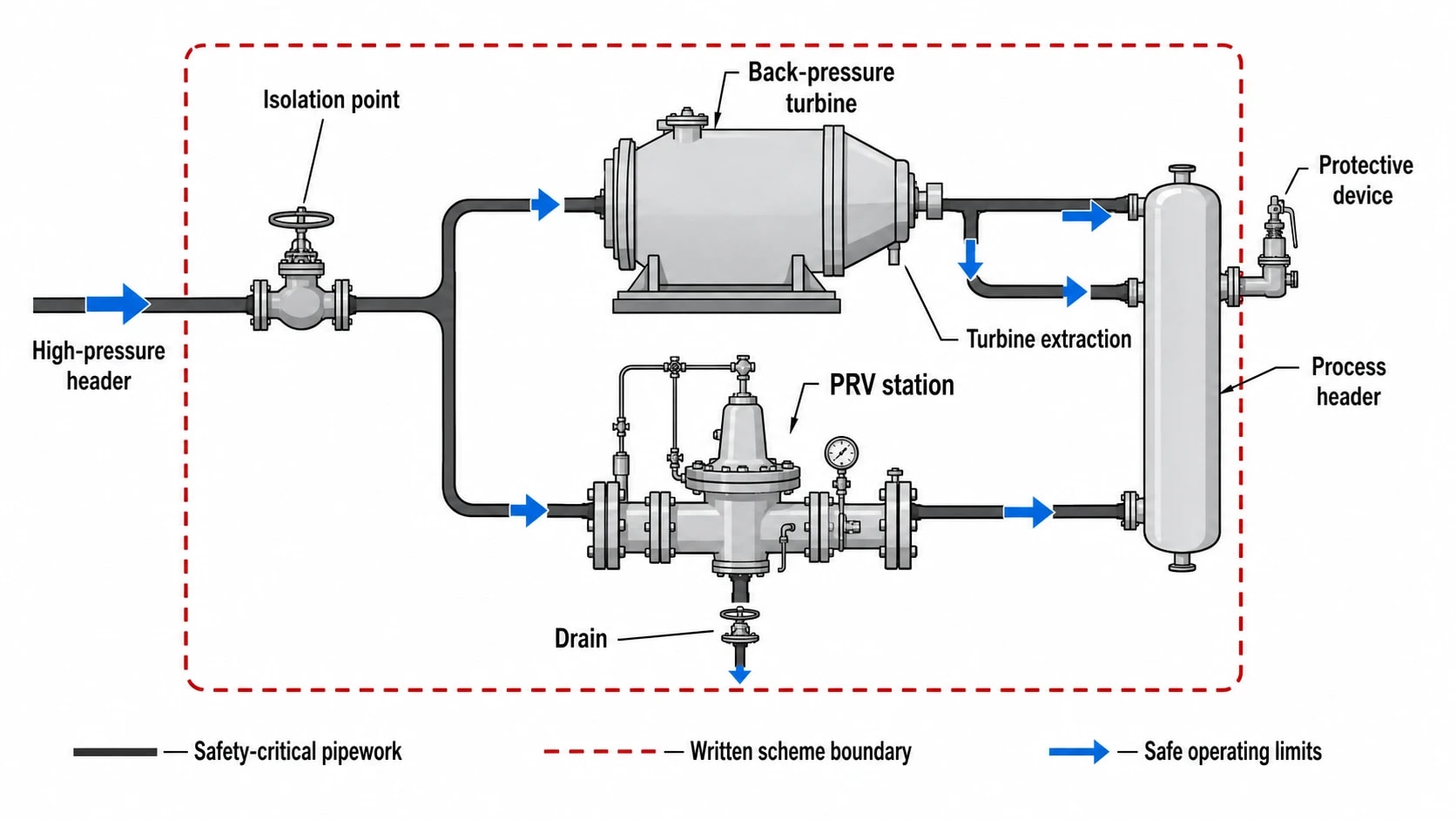
In the UK, the Pressure Systems Safety Regulations 2000 classify steam at any pressure as a relevant fluid. HSE states that qualifying pressure equipment requires a written scheme of examination and an examination before use. The dutyholder must also understand the system’s safe operating limits.
A reconciled header PFD should identify the safety-critical pipework, protective devices, PRV stations, turbine-extraction interfaces, isolation points and drains. This makes the engineering representation more useful to operations, maintenance and the competent person responsible for examination activities. It does not substitute for the written scheme of examination or its defined scope.
The model must retain safe operating limits as constraints. A proposal to lower header pressure, raise extraction flow or reduce a PRV’s role must be reviewed against turbine capability, pipework design, protective-device settings, process-control response and the applicable written scheme.
Make it part of energy management
ISO 50001:2018 remains the current international energy-management standard, with Amendment 1:2024. It provides a framework for energy-performance improvement rather than prescribing a specific steam-system design.
A reconciled steam header model can support that framework by defining credible energy-performance indicators. Examples include PRV steam flow by operating case, turbine power per tonne of qualifying steam, condensate return rate, boiler-feedwater temperature and unaccounted steam energy. Each indicator needs a documented boundary and operating context. A rising PRV flow during a production change may be appropriate; the same rise during stable production calls for investigation.
From balance residual to implementation roadmap
A credible steam header reconciliation produces a ranked list of actions rather than a generic energy-saving target. The action may be as small as repairing a faulty flow measurement or closing an unnecessary bypass. It may require control changes to favour turbine extraction within safe limits. It may also support a capital case for turbine refurbishment, a new back-pressure turbine, condensate recovery or a header redesign.
The correct sequence is evidence first, then intervention. A validated mill-wide balance shows whether steam is generated efficiently, whether its pressure is used productively, and whether the resulting condensate returns to support boiler operation. It provides the engineering basis for projects that reduce fuel use, improve power generation and protect the operating margin required by a pulp and paper mill.
This article reflects the independent analysis and editorial opinion of EnerTherm Engineering. Product names, trademarks, and brands mentioned belong to their respective owners. EnerTherm Engineering is not affiliated with, endorsed by, or a licensee of any third-party software or product mentioned unless explicitly stated.

Managing Director — EnerTherm Engineering
Dr. François Pierrel is Managing Director of EnerTherm Engineering with over two decades of expertise in thermal design, heat transfer, and industrial energy optimisation. He holds a PhD in Heat Transfer from Cranfield University and a Post-Doctorate from Heriot-Watt University.
