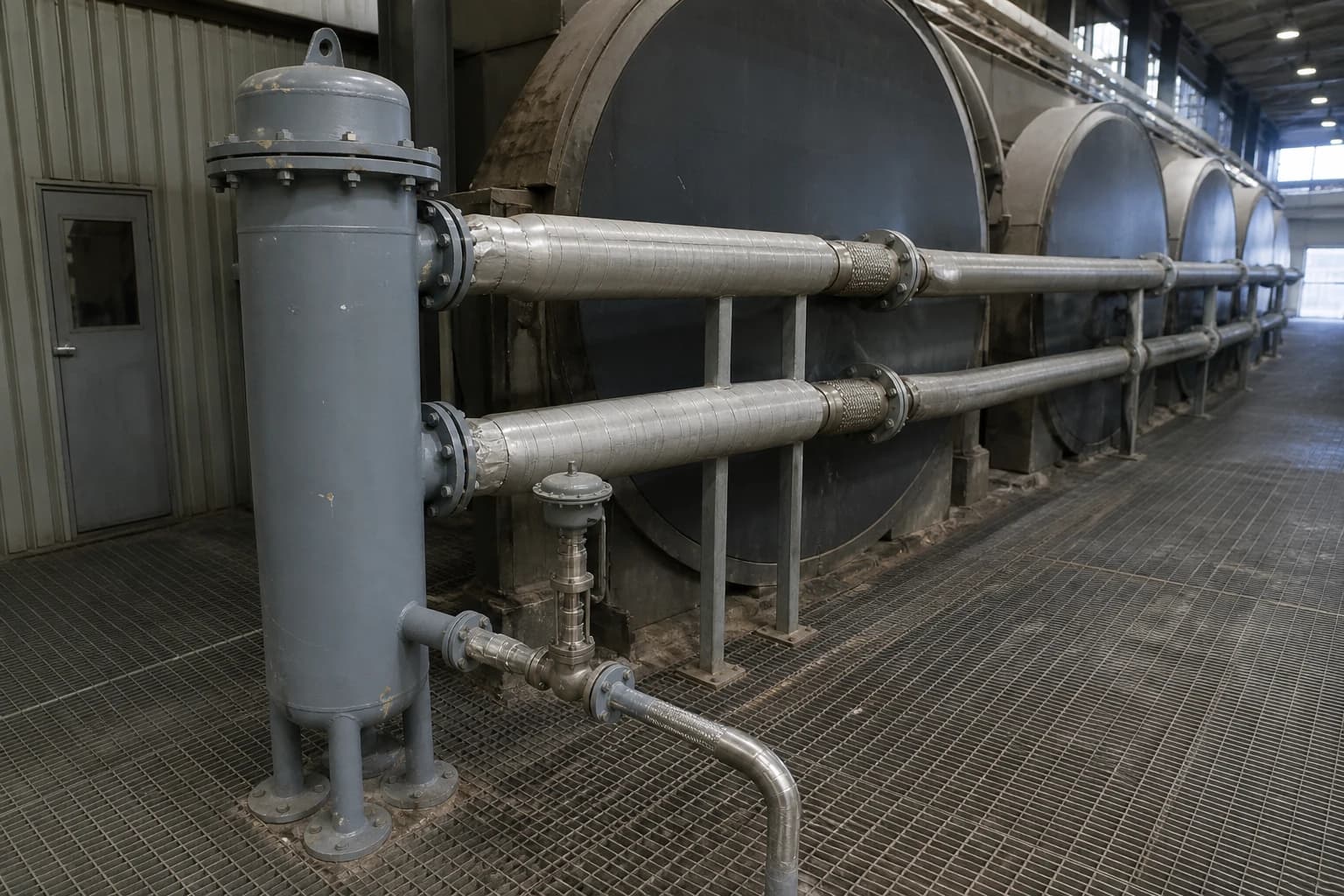
Condensate Management in Paper Production: Dryer Flooding
How siphons, separators and pressure differential prevent flooding and sheet defects.
Condensate management in paper production is the controlled removal, separation, return and reuse of water formed when steam condenses inside paper-machine dryer cylinders. A published three-machine case study of dryer-section heat recovery identified 110 GWh/year of process-heat savings, while implemented investments later delivered 12% lower fuel use and 24% lower CO₂ emissions.
Dryer flooding can erode those gains quickly. A cylinder that retains too much condensate loses heat-transfer performance, increases mechanical load and can create local dryer-temperature variation. The production consequence is familiar to mill utilities and process teams: moisture variation, reduced drying capacity, unstable machine operation and rising steam demand that does not translate into saleable output.
The remedy is rarely a single valve adjustment. Effective condensate management requires the dryer steam and condensate system to maintain the steam pressure needed for drying, remain stable through changes in speed and load, and remove condensate continuously from every cylinder.
Why dryer flooding raises energy use and affects sheet quality
Condensate creates thermal resistance inside the dryer
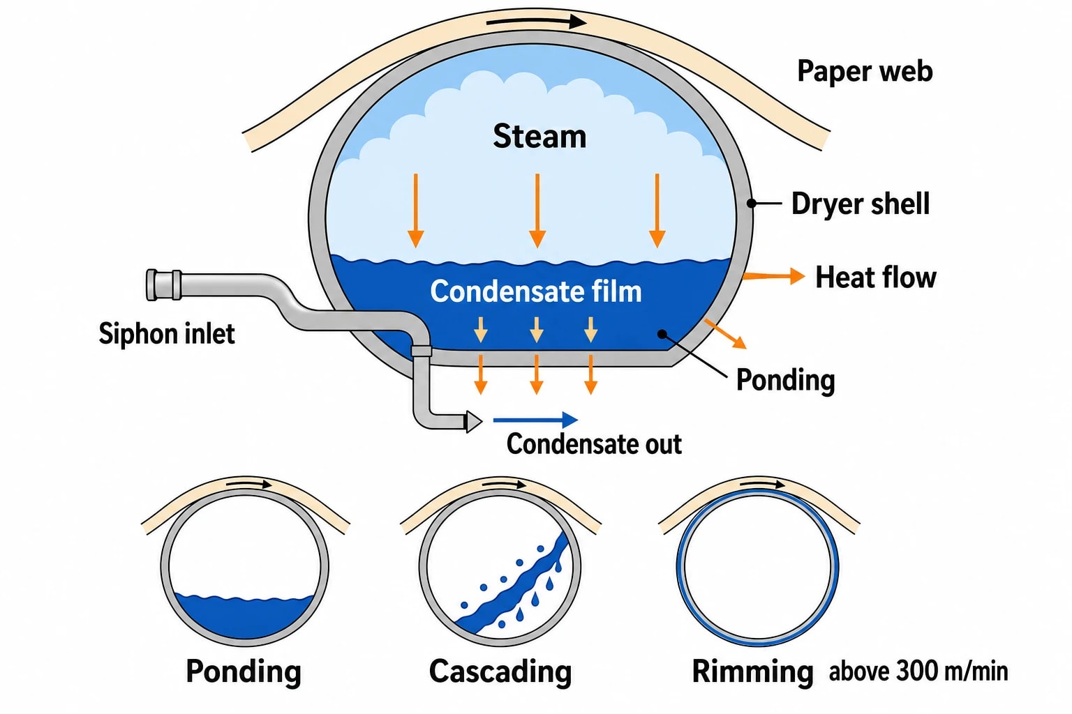
Steam transfers latent heat when it condenses on the inner dryer shell. The resulting condensate must leave the cylinder at the same rate that steam condenses. If it accumulates, the liquid film between steam and shell thickens. That film resists heat flow to the shell, reducing dryer surface temperature for a given steam pressure.
The effect often appears first as a loss of drying headroom. Operators may respond by increasing steam pressure, opening a control valve further or slowing production. Each response can increase fuel use, but none addresses the hydraulic restriction that caused the flooding.
The issue is particularly serious in dryer groups that determine final moisture or coating readiness. Uneven cylinder surface temperature can contribute to cross-direction moisture variation. A web with uneven moisture is harder to control downstream and can create problems in calendaring, winding, converting or corrugating.
Flooding also changes the mechanical duty
Flooded dryers carry extra liquid mass. TAPPI guidance notes that flooding can increase bearing load, gear forces and dryer-drive load. Where condensate does not form a stable rim, moving liquid can also produce variable torque.
The severity depends on dryer speed, diameter, steam pressure, condensate rate and siphon arrangement. Condensate behaviour moves through three operating descriptions:
- Ponding, where condensate gathers at the bottom of a slowly rotating cylinder.
- Cascading, where condensate lifts from the shell and falls through the cylinder.
- Rimming, where rotation holds condensate as a layer around the inner shell.
TAPPI TIP 0404-31 identifies rimming at speeds generally above 300 m/min, although the actual transition depends on operating conditions. A dryer system needs enough pressure differential to remove condensate in the prevailing regime, rather than at a convenient design-point assumption.
A flood can persist after the initial upset
A short loss of differential pressure can allow condensate to rise and submerge the siphon inlet. Restoring the former pressure differential may fail to clear the cylinder if the system now needs greater differential pressure to lift a denser liquid column through the siphon.
This explains a common operating pattern: machine speed and steam pressure appear normal after a sheet break or grade change, yet one dryer group remains cold, drive load stays elevated and drying performance does not recover. The condition needs positive diagnosis and a controlled recovery plan rather than repeated manual changes to steam-pressure setpoints.

Identify where your plant is losing energy and quantify the savings potential — our audits map every heat source, sink, and waste stream in your facility.
How steam, siphons and pressure differential control dryer drainage
Steam pressure and differential pressure have separate jobs
Steam pressure establishes saturation temperature and therefore the temperature available at the dryer shell. Differential pressure, often abbreviated to DP, supplies the driving force that moves condensate and uncondensed steam from the dryer to the condensate header.
These duties interact but should not be confused. Raising dryer steam pressure may improve the thermal driving force, but it does not guarantee drainage. Conversely, increasing DP can improve condensate removal while increasing blow-through steam if the control approach is poorly matched to the load.
A useful audit starts by mapping each dryer group:
- Steam supply-header pressure.
- Condensate-header or separator pressure.
- Pressure at representative dryer joints, where safe measurement points exist.
- Dryer speed, production rate, grade and sheet moisture.
- Steam flow, condensate flow and blow-through flow where instrumentation permits.
Header-to-header DP is a useful indicator, but it is not automatically the pressure difference experienced by every cylinder. Pressure losses in joints, flexible hoses, siphons, fittings, isolation valves and condensate piping can make local dryer DP materially different from the control-room reading.
Siphons determine the evacuation requirement
A siphon is the internal pipe that collects condensate close to the dryer shell and carries the mixture through the rotating joint. Siphon type, internal diameter, shoe geometry and clearance from the shell affect the flow needed to keep the condensate layer thin.
Rotary siphons rotate with the cylinder. They must overcome centrifugal effects as condensate travels from the shell towards the dryer centre. Stationary siphons remain fixed while the cylinder rotates around them. Their hydraulic behaviour differs, so the required DP and blow-through level must suit the installed configuration.
A siphon that is too small can restrict removal at high condensing load. A siphon that is oversized can pass excessive blow-through steam and reduce the available control range. Mechanical condition matters as much as nominal design. Worn shoes, damaged internal pipework, restricted joints and incorrect clearances can alter drainage performance after years of operation.
Blow-through steam is necessary, but it has a cost
Blow-through steam is uncondensed steam that exits through the siphon with condensate. It reduces the density of the two-phase mixture, helps evacuate non-condensable gases and supports drainage. Zero blow-through is not a practical target for most dryer arrangements.
Excessive blow-through wastes useful steam and can overload separators, thermocompressors or downstream low-pressure users. It can also destabilise cascade operation when a machine changes grade or experiences a sheet break.
The correct target is the minimum stable blow-through rate for the dryer group, speed and siphon configuration. A fixed valve position or site-wide DP target is unlikely to achieve that across wet-end, intermediate and after-dryer groups.
Separator performance and condensate recovery in a paper machine
The separator has two distinct outlets
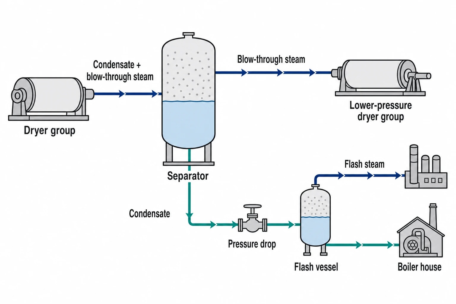
The dryer discharge reaches a separator as a mixture of condensate and blow-through steam. The separator provides space for condensate to settle and steam to separate at the top. Condensate leaves through the bottom outlet for recovery, while separated steam can feed a lower-pressure dryer group, air heater or another suitable process user.
Poor separator performance affects both energy recovery and drainage. A high separator pressure reduces the available DP across dryer cylinders. Liquid carry-over into the steam outlet can disrupt downstream use. Inadequate level control can create unstable back-pressure conditions and make drainage vary with separator inventory rather than dryer load.
An assessment should review:
- Separator pressure against each dryer-group operating requirement.
- Level trend, level-control response and evidence of hunting.
- Venting arrangements for air and non-condensable gases.
- Condensate outlet capacity and downstream restrictions.
- Blow-through-steam destination and its pressure stability.
- Evidence of liquid carry-over or erosion in outlet piping.
Flash steam must be accounted for
Condensate can flash when its pressure falls. Flash steam has energy value, but it also occupies volume and affects hydraulic capacity in return lines and vessels. A return arrangement designed as if it carries liquid alone can develop back-pressure, noise, vibration and unstable separator levels when two-phase flow increases.
The objective is to recover heat and water while protecting the pressure differential that dries the sheet. This requires the condensate route, separator pressure and flash-steam use to be assessed as one system.
Condensate quality has a financial value
Hot condensate returns sensible heat to the boiler house and reduces boiler make-up-water demand. Reduced make-up also lowers treatment-chemical demand and boiler blowdown volume. Where condensate cannot return because of contamination risk, its heat may still be recoverable through a suitable heat exchanger.
A mill should establish the actual destination of each condensate stream. A flow diagram may show recovery, yet bypasses, failed pumps, contamination diversions or poorly controlled flash vessels can send heat to drain or vent it at low value. Metered condensate return and boiler make-up provide a stronger audit baseline than schematic intent.
Diagnosing dryer flooding during an industrial energy audit
Start with operating evidence, not assumptions
Dryer flooding often hides within normal production variation. The clearest evidence comes from time-correlated data. Compare steam pressure, DP, separator pressure, machine speed, steam flow, dryer-drive load and moisture measurements across normal production, grade changes, start-up and sheet breaks.
A stable condition at one speed can be unstable at another. The audit record therefore needs production context for each trend, including basis weight, grade, target moisture and the dryer groups in service.
Thermal imaging can identify cooler dryer surfaces and temperature discontinuities, provided the survey accounts for guarding, hood conditions and safe access. Surface-temperature trends along the machine can reveal groups that do not track their steam conditions. Ultrasonic checks and targeted inspection can also identify leaking joints or control valves that fail to shut as intended.
Use a symptom-led fault check
| Observed condition | Likely condensate-management cause | Audit check |
|---|---|---|
| Dryer surface temperature falls below adjacent cylinders | Condensate film has thickened or non-condensables have accumulated | Compare local steam and drainage pressures, inspect siphon and joint condition |
| DP rises but drying does not recover | Flooded cylinder needs a higher recovery DP or siphon path is restricted | Confirm pressure at the dryer joint, not only at headers |
| Separator level oscillates | Outlet capacity, level-control tuning or flashing is destabilising the vessel | Trend level, pressure, valve position and downstream pressure together |
| Steam use rises after a sheet break | Blow-through control or pressure control has not returned to a suitable low-load state | Review break logic, pressure ramps and control-valve response |
| Moisture streaks recur in one dryer group | Uneven drainage or non-condensables are affecting cylinder heat transfer | Trend dryer-cylinder temperatures across the group and inspect venting arrangements |
| Condensate return falls while make-up rises | Condensate is bypassed, rejected or lost through a leak | Reconcile condensate flow with boiler make-up and identified drain routes |
Include sheet breaks and warm-up in the test plan
Sheet breaks sharply reduce condensate formation because the web no longer removes heat from the cylinders. Steam and condensate controls must remain stable at this low load, then transition back as the sheet returns. Warm-up creates a similar low-condensing-load condition.
These are the moments when a pressure-control loop, thermocompressor arrangement or separator outlet limitation can expose itself. A control strategy that performs only at normal production rate leaves the mill vulnerable to avoidable flooding and wasted blow-through steam.

Identify where your plant is losing energy and quantify the savings potential — our audits map every heat source, sink, and waste stream in your facility.
Practical improvements for condensate management in paper production
Prioritise controls before major equipment changes
Many mills can improve dryer drainage through measurement, setpoint rationalisation and repairs before considering a major rebuild. Priority actions commonly include verifying pressure transmitters, correcting impulse-line issues, confirming valve authority, repairing restrictions and reviewing the DP setpoint against siphon performance data.
The next step is to establish whether the existing system controls DP directly, controls blow-through flow or relies on another relationship such as thermocompressor operation. Each method needs a clear operating envelope and consistent response at low, medium and high condensing loads.
Match the solution to the dryer group
Wet-end groups, intermediate groups, after-dryer groups and Yankee dryers can have different pressure levels, loads and drainage constraints. A single intervention can therefore deliver unequal results across the machine.
Possible measures include stationary-siphon retrofits where appropriate, replacement or repair of worn siphon components, separator modifications, revised pressure-control architecture, improved flash-steam use and removal of excessive piping restrictions. Engineering teams should base decisions on measured pressure losses, equipment condition and production requirements rather than a generic flow target.
Any proposed change needs a planned start-up and commissioning procedure. DP should be confirmed at the affected dryers through warm-up, sheet-break recovery, grade changes and maximum intended speed.
Measure the energy result after the change
A condensate-management project needs more than a one-off steam-flow reading. The measurement plan should compare comparable grades and production conditions before and after the work while tracking:
- Specific steam consumption per tonne of saleable paper or board.
- Boiler fuel use and boiler make-up-water demand.
- Condensate-return temperature and quantity.
- Dryer-group DP and separator pressure.
- Machine speed, basis weight, moisture profile and break frequency.
- Dryer-drive load where flooding previously increased torque.
The Applied Thermal Engineering case study focused on heat-recovery improvements rather than dryer drainage alone. It shows that process changes can move installed equipment away from its original design condition, creating energy losses that become visible only when performance is measured against current operating practice.
UK pressure-system obligations for dryer-section modifications
PSSR governs safe use of installed steam systems
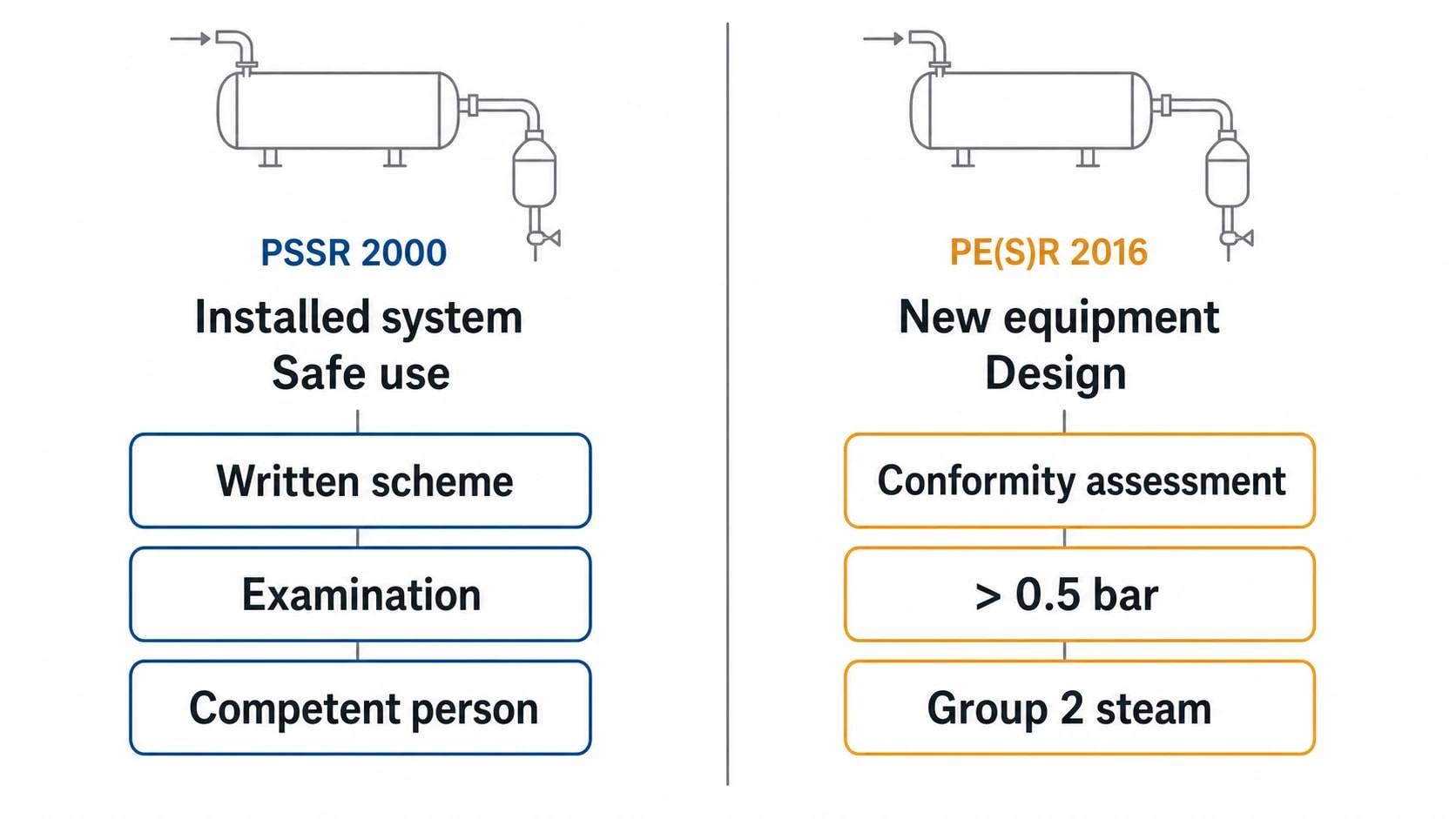
Under the Pressure Systems Safety Regulations 2000, steam at any pressure is a relevant fluid. For qualifying systems used at work, the dutyholder must ensure that a written scheme of examination is in place before operation and that examinations take place in accordance with that scheme.
A dryer-drainage retrofit can affect pipework, pressure vessels, protective devices, operating limits and examination arrangements. The dutyholder should involve the competent person early enough for the written scheme of examination and supporting records to reflect the modified system. Changes to pressure settings, separator duty or protection arrangements should form part of the site management-of-change process.
PE(S)R applies when pressure equipment or assemblies are supplied
The Pressure Equipment (Safety) Regulations 2016 apply in Great Britain to pressure equipment and assemblies with a maximum allowable pressure above 0.5 bar, subject to the regulations’ exclusions. The scope includes vessels, piping, safety accessories and pressure accessories. Steam is a Group 2 fluid under the regulations.
For a dryer-section project, the distinction matters. PSSR addresses the safe use of the installed system. PE(S)R addresses the design, manufacture and conformity-assessment requirements that apply when relevant pressure equipment or an assembly is placed on the Great Britain market or put into service. Project specifications should identify the actual pressure boundary, maximum allowable pressure, fluid category, joining requirements and documentation responsibilities before procurement begins.
Building a dryer-flooding roadmap
An effective dryer-section audit turns operating symptoms into a ranked improvement plan. It begins with a site walkdown and a verified steam-and-condensate balance, then combines production data with pressure, temperature, flow and condition evidence. The result should distinguish immediate repairs from controls work, piping changes and larger equipment investment.
EnerTherm Engineering’s paper and pulp energy-audit approach can frame that work around continuous production: identify the drainage constraint, quantify its energy and quality effect, test the proposed operating condition and set out a practical implementation sequence. The target is stable dryer drainage at the minimum steam demand that preserves production rate and moisture control.
This article reflects the independent analysis and editorial opinion of EnerTherm Engineering. Product names, trademarks, and brands mentioned belong to their respective owners. EnerTherm Engineering is not affiliated with, endorsed by, or a licensee of any third-party software or product mentioned unless explicitly stated.

Managing Director — EnerTherm Engineering
Dr. François Pierrel is Managing Director of EnerTherm Engineering with over two decades of expertise in thermal design, heat transfer, and industrial energy optimisation. He holds a PhD in Heat Transfer from Cranfield University and a Post-Doctorate from Heriot-Watt University.
