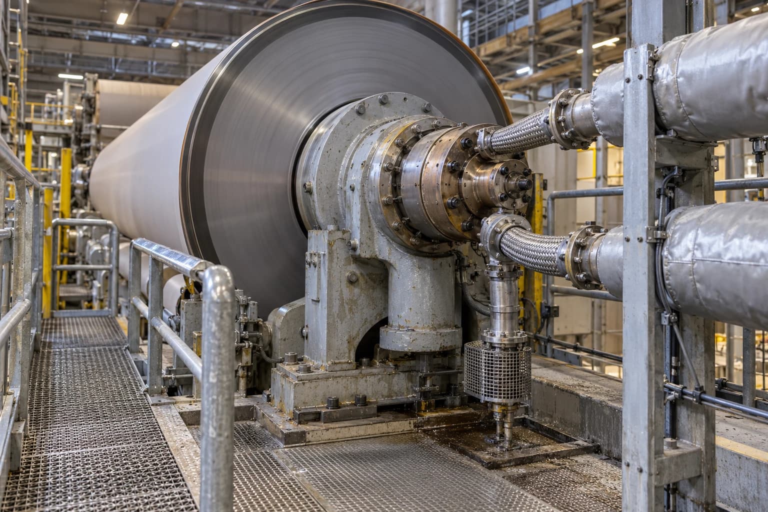
Condensate Evacuation in Paper Machines Above 350 mpm
Why blow-through control stabilises condensate flow as dryer speeds rise
Condensate evacuation is the controlled removal of condensate, blow-through steam and non-condensable gases from steam-heated dryer cylinders to sustain heat transfer and stable drying.
Above 350 mpm, dryer cylinders usually operate in a rimming condition. Centrifugal force holds condensate as a film against the rotating dryer shell rather than allowing it to pool at the bottom. Siphon geometry, steam-joint pressure loss, blow-through flow and differential-pressure control become closely linked.
A drainage system can appear adequate while consuming excessive blow-through steam. It can also maintain a group pressure setpoint while individual cylinders begin to flood. Both conditions damage drying performance. Condensate removal must match the condensing rate, with sufficient blow-through to transport two-phase flow and purge non-condensable gases.
Why condensate evacuation changes above 350 mpm
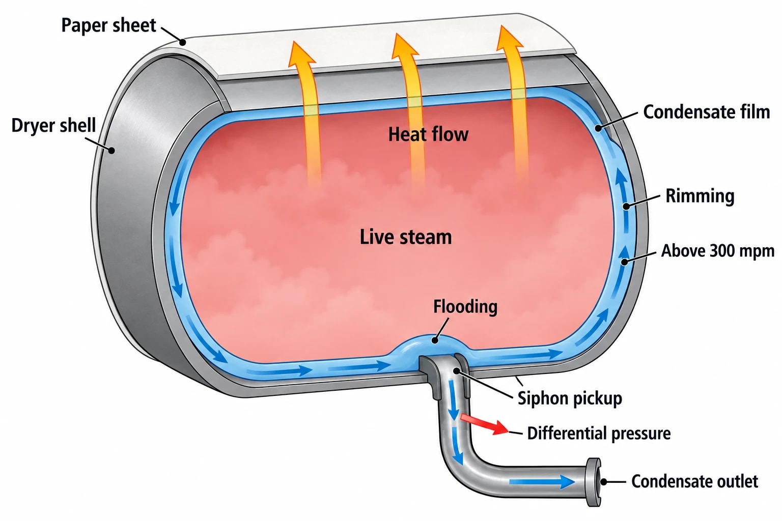
Steam condenses on the inner surface of a dryer cylinder, releasing latent heat through the shell and into the sheet. The condensate film creates thermal resistance between live steam and the shell, so its thickness, coverage and movement affect drying rate.
TAPPI TIP 0404-31 identifies three broad condensate conditions: ponding, cascading and rimming. Dryer speed and condensate volume have the greatest effect, while dryer diameter, steam pressure and condensate temperature also influence the transition.
| Condensate condition | Cylinder behaviour | Main evacuation concern |
|---|---|---|
| Ponding | Condensate gathers at the bottom of the dryer | Rising liquid level and mechanical loading |
| Cascading | Liquid lifts with the shell then falls | Variable load on the siphon and drive |
| Rimming | A liquid film rotates around the shell | Film thickness, siphon pickup and pressure control |
Rimming can begin above 300 mpm, making 350 mpm a sensible threshold for closer drainage scrutiny. The film is not itself a fault. High-speed dryer cylinders require a controlled condensate layer. Flooding develops when condensate forms faster than the siphon can remove it, causing the layer to thicken or become uneven.
What rimming does to dryer heat transfer
In a rimming cylinder, the condensate layer is part of the heat-transfer path. A thicker film increases resistance and reduces heat flow into the dryer shell. Lost drying capacity can emerge before operators see an obvious drainage failure.
Cylinder temperature checks offer a measurable field test. Valmet guidance uses a can-to-can temperature difference of no more than 5 to 10 °F, approximately 3 to 6 °C, as a diagnostic guide. The applicable tolerance depends on grade, dryer pressure programme and position in the section, so each mill should establish a baseline during stable production.
Cross-machine moisture patterns also need interpretation against site data. A cool centre and hotter dryer ends can indicate a rimming-film or siphon-clearance issue, as flow near cylinder edges may create greater turbulence. A moisture-frown profile alone does not prove poor condensate evacuation. Check it alongside cylinder surface temperatures, steam saturation temperature, group DP and siphon condition.

Map every energy and material flow in your process with detailed heat and mass balance calculations — the foundation for any optimisation or design project.
Stationary and rotary siphons for high-speed paper machines
The siphon carries the condensate and blow-through mixture from the rotating dryer to the steam joint and condensate return system. Its type determines how centrifugal force affects evacuation duty.
Rotary siphons
A rotary siphon attaches to the dryer shell and rotates with the cylinder. It can be spring-loaded or fixed in place, keeping its pickup shoe at a constant position relative to the shell. Correct shoe clearance can support uniform heat transfer during rimming service.
At higher speeds, condensate entering a rotary siphon must travel towards the cylinder centreline against centrifugal force. The required DP can rise with speed, together with the quantity and velocity of blow-through steam needed to entrain condensate.
Rotary siphons remain suitable for some high-speed duties. Selection depends on dryer diameter, rotational speed, journal arrangement, pressure, condensing load, piping resistance and the measured siphon performance curve. Paper-machine speed alone cannot justify a retrofit.
Stationary cantilever siphons
A stationary siphon remains fixed while the dryer shell rotates around it. In a cantilever arrangement, the pipe extends through the dryer journal from the steam-joint side. Once condensate enters the stationary pipe, it is no longer subject to the rotating shell’s centrifugal force.
During rimming, the kinetic energy of the moving condensate film can assist its passage towards the stationary siphon discharge. Properly sized stationary systems can therefore operate at lower DP than many rotary arrangements. TAPPI guidance gives 15 to 35 kPa as a normal operating range for a correctly sized stationary siphon with a matching steam and condensate system.
This range is a commissioning reference, not a group-wide default. The final target must reflect the dryer-specific J-curve, required blow-through flow, available return-header pressure and the condition of the siphon and steam joint.
Siphon shoe clearance and mechanical integrity
Siphon clearance affects drainage and heat transfer. A pickup positioned too far from the shell captures a larger condensate volume and can leave a thicker film behind. Excessively close clearance raises the risk of contact during runout, vibration or upset conditions.
Supplier guidance for stationary siphons commonly specifies a 3 to 8 mm clearance, subject to dryer design and manufacturer settings. Some designs use a PTFE support shoe to reduce the consequence of occasional shell contact, but PTFE does not compensate for poor alignment or worn support components.
An outage inspection should verify:
- Clearance at the shoe and consistency across comparable dryers.
- Shoe orientation relative to cylinder rotation.
- Wear on the shoe, elbow, vertical leg and internal pipe.
- Cantilever support condition and evidence of deflection.
- Rubbing marks, vibration damage and dryer-shell scoring.
- Steam-joint pressure loss and flexible-hose condition.
A progressive increase in DP after a clearance change or maintenance event deserves immediate attention. The control system may be compensating for an enlarged pickup gap, restricted return path or degraded steam joint.
Differential pressure control in rimming service
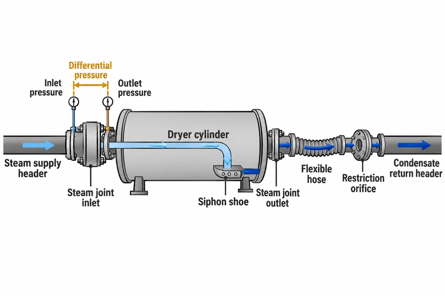
Differential pressure is the difference between dryer steam-supply pressure and condensate-return pressure. It provides the driving force for drainage, although pressure measured at headers includes more than siphon duty.
The pressure-loss path includes the siphon shoe, internal piping, steam joint, flexible hose, valves, fittings, condensate line, restriction orifice and separator connection. A target that looks reasonable at group headers can conceal excessive loss at an individual joint or return line.
Use the J-curve to set the operating point
A J-curve plots dryer differential pressure against blow-through steam flow for defined operating conditions. It shows the combined performance of the cylinder, siphon, steam joint and external piping.
The curve changes with:
- Machine speed and dryer diameter.
- Steam pressure and condensing load.
- Siphon type, pipe diameter and pickup configuration.
- Blow-through steam fraction.
- Orifice restriction and return-line condition.
TAPPI describes fixed and managed differential-pressure control. Managed DP control adjusts the target using operating conditions such as speed, steam pressure and condensing load. It can reduce DP during a sheet break or when dryers are isolated, avoiding the waste of holding a normal-running setpoint through every operating condition.
Measurement quality determines control quality
DP instrumentation requires as much care as the mechanical equipment. TAPPI advises locating transmitters below the headers, with sensing lines sloped downwards and filled with water to prevent trapped air. Air pockets and poorly sloped impulse lines create inconsistent readings that can make a stable drainage system appear unstable.
Pressure measurements at the inlet and outlet of individual steam joints help separate internal dryer losses from external pipework losses. This matters when one dryer runs cool or demands higher DP than its neighbours. Raising group DP will not repair a blocked joint, eroded pickup shoe or restricted hose.

Map every energy and material flow in your process with detailed heat and mass balance calculations — the foundation for any optimisation or design project.
Blow-through control during sheet breaks
Blow-through steam is the uncondensed steam leaving a dryer with condensate. It lowers the density of the two-phase mixture, assists entrainment and carries non-condensable gases from the cylinder. Its required quantity depends on siphon type, condensing rate, steam pressure, piping and machine speed.
For a stationary siphon, TAPPI guidance identifies blow-through of 10 to 15% of condensing load by mass as typical. Rotary arrangements may require a higher proportion. Excess flow increases two-phase velocity, pipe erosion, return-header pressure loss, separator loading and steam demand.
Why fixed DP can create a break-related surge
A sheet break sharply reduces condensing load. Siphon resistance also falls, changing the relationship between DP and blow-through flow. A simple DP controller may continue opening its discharge path to hold the existing pressure target even though the dryer requires less driving force.
A technical note on dryer steam control reports blow-through increases of more than 200% of the normal running requirement in a defined sheet-break scenario where condensing load falls to roughly 10% and simple differential-pressure control remains active. The increase depends on controller arrangement, siphon resistance, pressure setpoint and downstream equipment. It is a potential failure mode, not a universal sheet-break factor.
How blow-through control changes the response
Blow-through control manages flow rather than relying only on pressure difference between headers. Systems can control mass flow, a mass percentage of condensing load, volumetric flow or pressure drop across an engineered restriction orifice. Controlling pressure drop across the orifice is common.
When condensing load falls during a break, blow-through control reduces dryer DP to maintain the selected flow condition. The dryer remains evacuated while the separator, thermocompressor and vent system avoid an unnecessary steam surge.
Investigate this approach where operators see repeated break-related venting, separator-level instability, thermocompressor cycling or sharp steam-flow excursions. Restriction sizing, pressure-transmitter calibration and downstream separator duty must be checked before a control change enters service.
Diagnosing poor condensate evacuation in paper machines
A dryer drainage investigation must separate siphon and steam-system faults from other drying constraints. Press dryness, fabric condition, pocket ventilation, sheet temperature and surface contamination also affect dryer performance.
Field symptoms that point towards drainage problems
Poor condensate evacuation often produces a pattern rather than a single alarm:
- Individual cylinder surface temperatures fall away from the group trend.
- Can-to-can temperature differences exceed the mill’s established stable-running baseline.
- Group DP rises without a matching change in speed, grade or press dryness.
- Steam flow increases while production conditions remain similar.
- Condensate-header pressure fluctuates with separator level.
- Thermocompressor demand or venting rises after breaks.
- Siphon noise, vibration, shoe wear or shell-contact marks appear during inspection.
- Moisture-profile variation coincides with cylinder temperature variation.
Trend these values through normal production, grade changes, speed ramps and sheet breaks. A single snapshot cannot distinguish a temporary process response from a persistent drainage restriction.
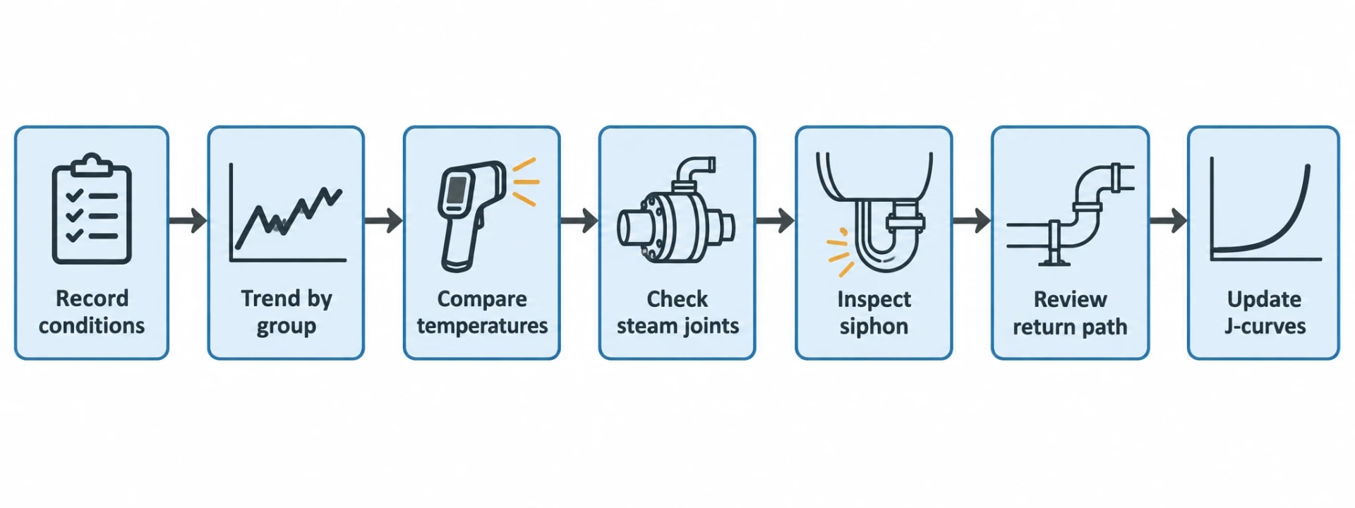
A practical investigation sequence
-
Record grade, speed, basis weight, press dryness, sheet moisture and active dryer configuration.
-
Trend steam pressure, condensate pressure, DP, steam flow, separator level and vacuum conditions by dryer group.
-
Compare dryer-shell surface temperatures with expected steam saturation temperatures and adjacent cylinders.
-
Check pressure loss across individual steam joints and compare results within each group.
-
Inspect siphon shoe clearance, orientation, support condition and internal wear during a safe outage.
-
Review return piping, flexible hoses, valves and restriction-orifice condition before changing a DP target.
-
Develop or update J-curves for the relevant grade and speed range before committing to a permanent control or hardware modification.
This sequence prevents a local restriction being hidden by higher DP and protects the dryer section from unnecessary blow-through steam.
UK safety requirements for dryer drainage modifications
A dryer cylinder, steam joint, siphon and connected pipework form part of a pressure system. In Great Britain, the Pressure Systems Safety Regulations 2000 apply to steam at any pressure.
A revised restriction orifice, siphon retrofit, control-valve change or steam-joint replacement should pass through the mill’s management-of-change process. The review should establish safe operating limits, assess protection arrangements, update design information and determine whether the written scheme of examination needs revision.
The Health and Safety Executive requires a suitable written scheme of examination for qualifying pressure equipment before use, with examination by a competent person. Dutyholders must account for stored energy, hot surfaces, rotating cylinders and the release of hot condensate during maintenance.
Inspection teams should isolate steam, depressurise the relevant equipment, verify safe access and follow the mill’s approved procedure before entering the dryer area or handling siphon components. Close clearance is valuable only when the siphon remains mechanically sound throughout the operating range.
This article reflects the independent analysis and editorial opinion of EnerTherm Engineering. Product names, trademarks, and brands mentioned belong to their respective owners. EnerTherm Engineering is not affiliated with, endorsed by, or a licensee of any third-party software or product mentioned unless explicitly stated.

Managing Director — EnerTherm Engineering
Dr. François Pierrel is Managing Director of EnerTherm Engineering with over two decades of expertise in thermal design, heat transfer, and industrial energy optimisation. He holds a PhD in Heat Transfer from Cranfield University and a Post-Doctorate from Heriot-Watt University.
