
Strategies for Improving Burner Efficiency in Crude Oil Heaters
Crude oil heaters (also known as fired heaters or process furnaces) are critical components in refineries and chemical processing, consuming a significant portion of a plant's total fuel. Their primary function is to heat crude oil to specific temperatures, reducing its viscosity for efficient transportation and facilitating separation processes like distillation. Given their substantial energy consumption, even small improvements in burner efficiency can lead to considerable cost savings, reduced emissions, and enhanced operational reliability.
Optimising these fired heaters involves a multifaceted approach, addressing burner design, combustion control, heat transfer mechanisms, and overall system maintenance. To drive real-world performance, it is vital to distinguish between combustion efficiency (the burner's capacity to completely release the chemical energy of the fuel) and overall thermal efficiency (how much of that released energy is successfully absorbed by the crude oil process fluid).
The Core Principles of Burner Efficiency
Burner efficiency is fundamentally governed by the thermodynamics of combustion. The process requires a precise mixture of fuel and oxygen to convert chemical energy into thermal energy. The combustion efficiency (Ec) of an industrial burner can be mathematically formulated using an energy balance:
Ec=QinQin−Qloss×100where:
- Ec is the combustion efficiency (%).
- Qin is the total thermal energy input of the fuel based on its Net Calorific Value (NCV) or Lower Heating Value (LHV).
- Qloss is the sum of energy losses, primarily consisting of sensible heat carried away by dry stack gases and latent heat lost to water vapour formed during combustion.
To maximise Ec, the burner must achieve complete combustion of the fuel hydrocarbons with the minimum possible amount of excess air. If excess air is too high, the extra nitrogen and oxygen absorb flame energy and carry it out of the stack as sensible heat loss. If excess air is too low, incomplete combustion occurs, producing carbon monoxide (CO) and soot, which represents wasted chemical energy and causes rapid fouling of heat transfer surfaces.
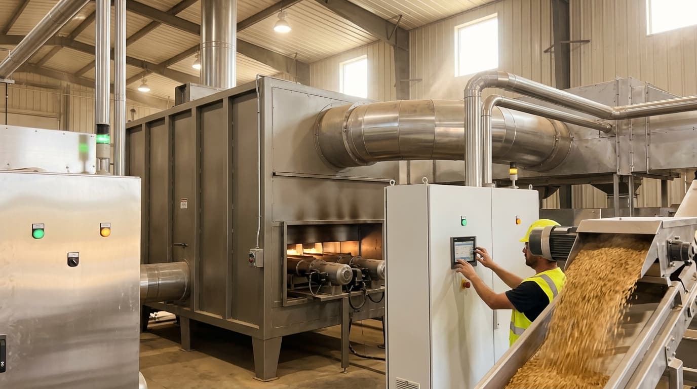
Direct and indirect-fired process heating systems for grain drying, baking, textile finishing, metal treatment, and industrial thermal processes.
Advanced Burner Technologies for Enhanced Efficiency
Modern burner designs play a pivotal role in achieving higher efficiency and lower emissions. The evolution of oil and gas burners has continuously aimed to improve efficiency and capacity to handle modern heating demands.
Low-NOₓ and Ultra-Low NOₓ Burners
Low-NOₓ burners (LNBs) and Ultra-Low NOₓ burners (ULNBs) are engineered to reduce the formation of thermal nitrogen oxides (NOₓ), which are harmful atmospheric pollutants, while maintaining or improving combustion efficiency. They achieve this by staging the combustion process into distinct zones:
- Fuel Staging: A portion of the fuel is injected downstream of the primary ignition zone, creating a fuel-lean primary zone that lowers the peak flame temperature.
- Air Staging: Air is introduced progressively, limiting the available oxygen in the high-temperature zone where thermal NOₓ is most readily generated.
- Internal Flue Gas Recirculation (IFGR): Modern ULNBs use the kinetic energy of the fuel gas jets to draw inert, cooler flue gases back into the burner flame. This dilutes the combustion zone, lowers the peak flame temperature, and reduces thermal NOₓ production without requiring high levels of excess air.
Implementing low-NOₓ burners is a key strategy for environmental compliance and can be integrated with advanced control systems for optimal performance.
Forced Draft Burners
Unlike natural draft burners that rely solely on stack effects (buoyancy forces created by hot gas density differences) for air supply, forced draft burners use a fan to supply combustion air. This provides precise, active control over the air-fuel ratio, allowing for optimised combustion and preventing issues like flame pulsation or flashback.
Forced air supply with micro-positive pressure combustion can significantly improve combustion efficiency and reduce pollution. It also permits the integration of air preheaters (APH), which capture waste heat from the stack to warm incoming combustion air. Preheating the combustion air can increase overall system efficiency by 1% for every 20 °C temperature rise.
| Parameter | Natural Draft Burners | Forced Draft Burners |
|---|---|---|
| Air Supply Method | Natural draft stack buoyancy | Mechanical fan/blower |
| Typical Excess Oxygen (O2) | 4.0% to 6.0% | 1.5% to 3.0% |
| Draft Control Sensitivity | Highly sensitive to ambient wind & temperature | Stable; actively controlled |
| Air Preheating Potential | Extremely limited / impractical | Highly compatible with Air Preheaters (APH) |
| Flame Geometry Control | Moderate | High |
Optimising Combustion Air and Fuel Management
The heart of burner efficiency lies in precise control over the combustion process, specifically the air-fuel ratio.
Precise Air-Fuel Ratio and Oxygen Trim Control
Maintaining an optimal air-fuel ratio is paramount. Too much excess air reduces flame temperature and efficiency, leading to higher energy prices, while too little air can result in incomplete combustion, soot formation, and equipment damage. Continuous measurement of oxygen (O2) and combustibles (CO) in the flue gas, particularly in the radiant section and at the convection inlet (bridge wall), provides crucial data for effective heater operation.
A 10% reduction in excess air can improve efficiency by 1% to 2%. To implement this practically, modern refineries install automated Oxygen Trim Control Systems. These systems use real-time data from zirconium oxide O2 analysers to adjust the burner air dampers or fan speed (via Variable Speed Drives) dynamically.
By adding a carbon monoxide (CO) analyser, operators can implement CO-influenced O2 trim control. Because CO is an incredibly sensitive indicator of incomplete combustion, the control system can safely drive excess oxygen levels down to their absolute physical limit (typically between 1.5% and 2.0% O2 for gas burners) before CO breakthrough occurs.
Fuel Gas Optimisation and Variability Management
Fired heaters in refineries often use a mix of fuels, including natural gas, refinery off-gases, and residual heavy fuels. The varying calorific value and composition of these fuels can lead to performance decline. Highly volatile hydrogen-rich gases combust differently from heavier hydrocarbons, altering the flame shape, length, and heat release profile.
To mitigate this, operators use the Wobbe Index (WI) to assess fuel gas compatibility and combustion stability:
WI=SGHHVwhere:
- WI is the Wobbe Index of the fuel gas (MJ/m³).
- HHV is the Higher Heating Value of the fuel (MJ/m³).
- SG is the Specific Gravity of the fuel gas relative to air.
Optimising the combustion process by incorporating more stable fuels or by using real-time gas chromatography-mass spectrometry (GC-MS) data to accurately calculate mass fractions of individual compounds allows for more precise burner flow rate determinations. This approach leads to substantial energy savings by tailoring the fuel supply to the specific thermal needs of each processing unit.
Furthermore, using mass flow control instead of volumetric flow control for fuel gas helps stabilise energy content and air requirements, leading to lower energy costs and emissions.
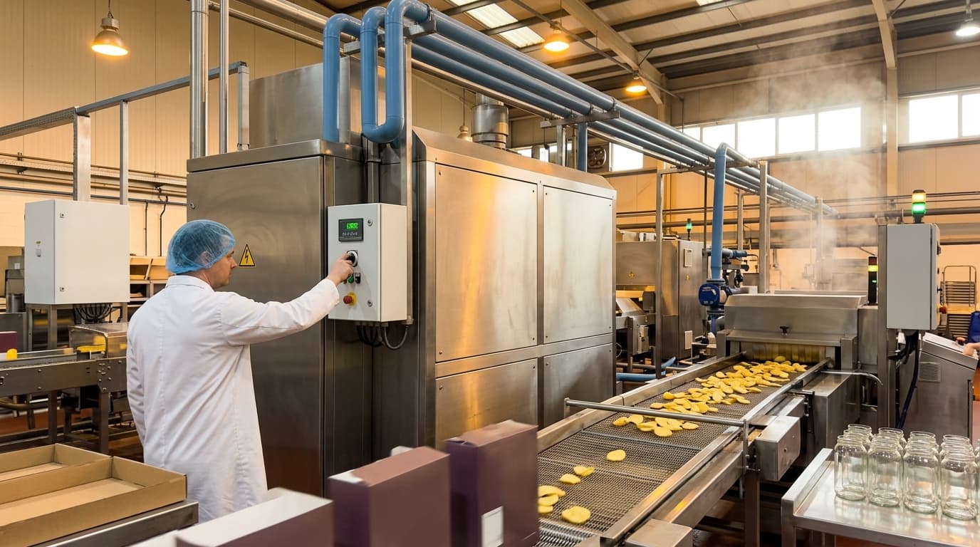
Reliable process heat generation from 100kW to 10MW+ — gas, oil, or biomass-fired, with precise temperature control and high turndown ratios.
Enhancing Heat Transfer in Heater Sections
Efficient heat transfer is fundamental to overall crude oil heater performance. A fired heater comprises a radiant section and a convection section, each playing a distinct role in heat transfer.
Radiant Section Optimisation
The radiant section is where most of the heat transfer occurs directly from the flame to the tubes via radiation. It accounts for approximately 70% to 85% of the total heat absorbed. Strategies for optimising this section include:
- Uniform Heat Flux Distribution: Irregular heat flux can lead to hot spots, process fluid degradation, coke formation, and potentially tube failure. Designing for uniform heat flux density around the process coil reduces coking and prevents scorching of crude oil. Optimisation of extended surfaces on tubes can significantly improve the uniformity of heat flux distribution.
- Preventing Flame Impingement: Short-flame burners or flat-flame burners prevent flames from directly impinging on the process tubes. Flame impingement causes severe localised overheating, accelerating internal coking (carbon deposition inside the tube), which increases heat resistance and risks tube rupture.
- High-Emissivity Ceramic Coatings: Applying high-emissivity ceramic coatings to the refractory brick walls of the radiant section increases their ability to absorb and re-radiate thermal energy back onto the process tubes. This reduces the heat lost through the heater casing and lowers the required combustion temperature, directly saving fuel.
Convection Section Improvements
The convection section recovers additional heat from the hot flue gases before they exit the stack, preheating the crude oil before it enters the radiant tubes.
- Economisers and Waste Heat Recovery Units (WHRUs): Installing economisers in the convection section is a highly effective method for recovering waste heat. WHRUs capture thermal energy from hot exhaust and gas discharge, repurposing it for heating oil, generating steam, or warming other plant media, thus significantly increasing overall thermal efficiency. This can lead to system-wide efficiency increases of 5% to 10%.
- Finned and Studded Tubes: In the convection section, finned or studded tubes are used to enhance convective heat transfer by vastly increasing the metal surface area available for heat exchange.
- Maintaining Cleanliness: Fouling (soot, ash, and inorganic deposits) in the convection section acts as an insulator, impeding heat transfer and increasing stack temperatures. Regular cleaning, using automated soot blowers or chemical wash programmes during turnarounds, is essential to maintain heat transfer efficiency.
Operational Best Practices and Maintenance
Beyond hardware design, daily operational practices and diligent maintenance are crucial for sustaining high burner efficiency.
Calculating and Monitoring Heater Efficiency
Process plants should monitor heater thermal efficiency using the heat-loss method as defined in industrial standards like API Standard 560 (5th Edition, 2016) or ASME PTC 4-2013 (reaffirmed 2023). The overall heater thermal efficiency (η) can be approximated via:
η=100−(LG+LH+LR+LU)where:
- η is the thermal efficiency of the heater (%).
- LG is the dry flue gas sensible heat loss (%).
- LH is the latent heat loss due to water vapour formation from fuel hydrogen (%).
- LR is the radiation and convection heat losses from the external casing (%).
- LU is the loss due to unburnt fuel, carbon monoxide, or soot (%).
By continuously tracking these values using process data historians, engineers can pinpoint whether efficiency drops are caused by burner misadjustment (high LU or LG) or convective fouling (rising stack gas temperature driving up LG).
Draft Control and Tramp Air Elimination
Proper draft control is essential for optimal combustion and reducing emissions. Draft is the negative pressure inside the heater created by the stack effect.
To prevent flue gas leaks into the environment, heaters are designed to operate under slight negative pressure. However, maintaining the correct negative pressure at the convection section inlet (the arch or bridge wall) is critical:
- Target Pressure: Typically, draft should be maintained at approximately -2.5 mm H₂O (-0.1 inches of water column) at the arch.
- The Danger of Excess Draft: Excessive negative pressure draws in ambient "tramp air" through casing cracks, open peepholes, explosive doors, and burner registers. Tramp air bypasses the combustion zone, absorbs thermal energy, cools the radiant section, and exits the stack as dry gas loss, severely degrading burner efficiency.
- Regulation: Draft is regulated by adjusting stack dampers and burner registers. Automated stack damper actuators integrated into the control loop ensure optimal draft is maintained across varying burner firing rates.
Advanced Process Control (APC)
Implementing advanced control systems, such as Multivariable Predictive Control (MPC), allows for dynamic optimisation of burner operation. These systems can continuously monitor and adjust parameters like fuel flow, air intake, and process outlet temperatures based on real-time data, ensuring optimal combustion and heat transfer efficiency. Linear regulation control strategies have been shown to improve energy efficiency by decreasing exhaust gas temperatures and lowering CO₂ emissions.
Regular Preventive Maintenance and Inspections
Routine maintenance is vital for efficient operation. A rigorous inspection programme should include:
- Burner Tip Cleaning: Fuel oil or gas burner tips must be kept free of carbon deposits and physical wear to maintain the design spray pattern and fuel atomisation.
- Casing Inspection: Visual inspection, supplemented with thermographic infrared cameras, helps identify hot spots on the heater casing. Hot spots indicate degraded internal refractory insulation, which increases radiation loss (LR).
- Seal Integrity: Repairing damaged gaskets on manways, sight glass doors, and burner mounting flanges prevents air in-leakage.
Conclusion
Improving burner efficiency in crude oil heaters is a multifaceted endeavour that offers substantial economic and environmental benefits for the chemical processing and oil and gas industries. By integrating advanced burner technologies (such as low-NOₓ and forced draft systems), meticulously managing combustion air and fuel composition, optimising heat transfer across radiant and convection sections, and adhering to rigorous operational and maintenance practices, companies can significantly reduce fuel consumption, lower greenhouse gas emissions, and enhance the overall reliability and lifespan of their critical heating infrastructure.
