GMP-Compliant Energy Saving Projects That Pass Validation
A regulatory framework for validating HVAC, clean utility and refrigeration savings.
On 25 August 2024, the final deferred provision of EU GMP Annex 1 took effect, completing implementation of the revised requirements for sterile medicinal product manufacture. Energy-saving work in a pharmaceutical facility must therefore preserve the contamination-control and qualified-state evidence required for any GMP change.
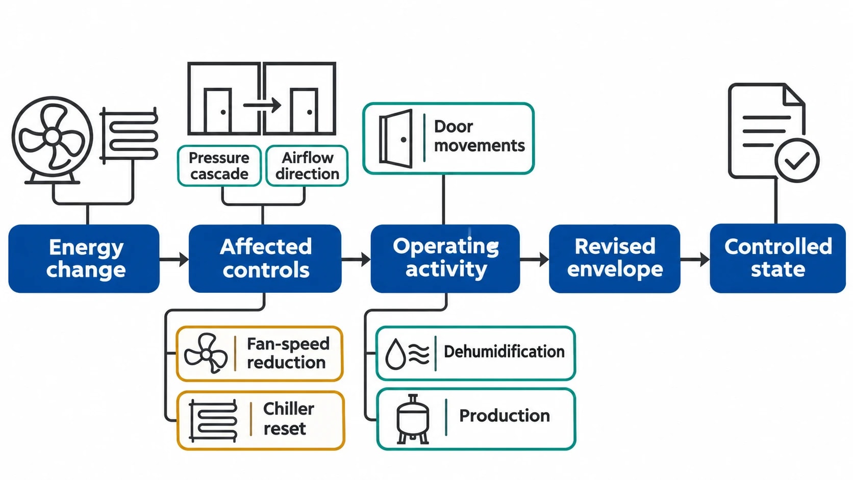
GMP-compliant energy-saving solutions cover more than lower utility consumption. A revised air-handling-unit setpoint, variable-speed drive, chilled-water reset, heat-recovery loop or refrigeration sequence can alter airflow, pressure differentials, temperature, humidity, alarm response or clean-utility conditions. Each may affect controls that protect product quality.
Facilities, utilities, quality assurance and validation teams must define the intended energy change, identify its GMP impact, set acceptance criteria before implementation, then demonstrate that the revised system operates in a controlled state.
GMP compliant energy saving solutions start with the contamination control strategy
EU GMP Annex 1 requires a contamination control strategy, or CCS, for a sterile manufacturing facility. It should identify critical control points and assess the combined effectiveness of design, procedural, technical, organisational and monitoring controls.
The CCS is the starting document for energy work in classified and sterile areas. It defines the environmental controls that an energy project must preserve.
Map the energy measure to the control it could affect
A facility team should connect each proposed measure to the relevant quality controls before choosing equipment or amending a sequence. A fan-speed reduction may influence room recovery, pressure-cascade performance, airflow direction and environmental-monitoring trends. A chiller reset may alter dehumidification performance and condensation risk. Heat recovery may introduce an indirect-contact risk through a heat exchanger.
The assessment should cover actual operating conditions, including production, cleaning, material transfers, door movements and maintenance. An empty-room check does not show that the revised system protects the product during normal activity.
For a classified area, relevant controls commonly include:
- Cleanroom grade and defined environmental conditions
- Pressure differentials and intended airflow direction between adjacent rooms
- Temperature and relative-humidity limits justified by the process and product
- Airflow volume or air-change rate justified by contamination risk and room use
- Airflow visualisation results
- HEPA-filter integrity and maintenance status
- Environmental monitoring, alarms, deviations and investigation history
- Cleanability, access and maintenance arrangements
Annex 1 permits risk-based engineering, supported by evidence
Annex 1 does not prescribe one fixed air-change rate for every cleanroom. It requires manufacturers to apply quality risk management, use scientifically justified controls and show that the facility remains effective in preventing contamination.
A long-standing fan setting or air-change rate may reflect an old design assumption rather than the current contamination risk. Equally, a lower airflow rate needs a documented technical and quality rationale. The site must demonstrate that the revised operating envelope maintains the required cleanroom conditions.
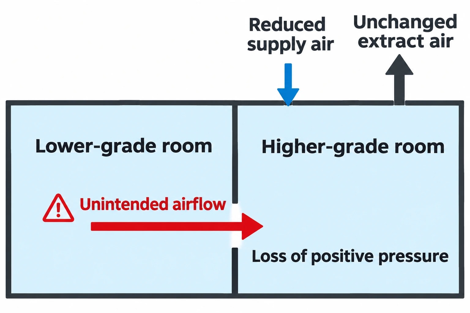
For sterile operations, Annex 1 states that cleanrooms should maintain positive pressure and/or airflow relative to lower-grade background areas under all operating conditions. It gives 10 Pascals as the guidance value for pressure differences between adjacent rooms of different grades, while recognising that containment requirements may justify a different arrangement.
Identify where your plant is losing energy and quantify the savings potential — our audits map every heat source, sink, and waste stream in your facility.
Annex 15 provides the validation route for energy projects
EU GMP Annex 15 applies to facilities, equipment, utilities and processes used to manufacture medicinal products. It requires planned changes that could affect product quality to be formally documented and assessed for their impact on the validated state or control strategy.
Energy conservation becomes a controlled GMP project when it changes an operating parameter, utility, facility, equipment item or computerised control function relevant to product quality.
Write a change description that engineering and QA can test
“Optimise HVAC” does not define a change that a validation team can qualify. The record should identify the asset, modification, operating range, interfaces and intended energy objective.
A suitable scope might state:
- Install a variable-speed drive on the supply fan serving a Grade C suite.
- Revise the minimum fan-speed limit and differential-pressure control sequence.
- Retain the approved temperature, relative-humidity and pressure-differential limits.
- Establish a new qualified operating range for the drive and associated airflow control.
- Verify alarm response, recovery performance and environmental-control performance before release.
The change assessment should identify direct and indirect effects. Annex 15 requires risk assessment where HVAC systems could have direct contact with product, or indirect contact through heat exchangers.
Set acceptance criteria before the work begins
Annex 15 requires validation protocols to define critical systems, attributes and parameters alongside their acceptance criteria. This prevents a project team from selecting convenient limits after results are available.
Acceptance criteria should derive from the CCS, approved user requirements, current qualification records, registered process requirements and documented product knowledge. They may include pressure-differential ranges, airflow direction, recovery time, temperature distribution, alarm performance, utility quality and relevant environmental-monitoring results.
| Qualification stage | Purpose for an energy project | Typical evidence |
|---|---|---|
| User requirements specification | Defines the required quality and engineering performance | Approved limits, functional requirements, alarm requirements and interfaces |
| Design qualification | Confirms the proposed design meets GMP and user requirements | Design review, risk assessment, control narrative and drawings |
| Installation qualification | Confirms correct installation or modification | Wiring checks, calibration records, equipment details and updated drawings |
| Operational qualification | Demonstrates operation across the defined range and fault conditions | Interlock tests, alarm challenges, control tests and operating-range checks |
| Performance qualification | Demonstrates effective performance in the intended operating environment | Environmental trends, pressure data, airflow visualisation and process-related evidence where relevant |
The level of qualification should reflect the risk. A revised fan-control loop serving a Grade B background area requires greater scrutiny than a lighting-control change in an administrative building.
Manage deviations openly
Annex 15 requires results outside predefined acceptance criteria to be recorded as deviations and fully investigated. The validation report should evaluate the consequence for the qualified state and recommend the formal next action.
A missed pressure target, failed alarm challenge or unexpected condensation event is quality evidence, not a commissioning inconvenience. It may require a revised design, retesting, a wider impact assessment or retention of the existing operating condition.
Validating HVAC energy savings without weakening cleanroom control
HVAC offers energy-saving opportunities because filtration, outdoor-air conditioning, dehumidification, cooling, reheating and fan operation run for long periods. It also presents the greatest risk of changing the physical controls that prevent contamination.
Establish a representative baseline
A baseline should capture the facility’s actual state before a setpoint or hardware change. The data must cover relevant operational modes and seasonal conditions.
For an air-handling project, this normally includes supply, return and extract airflow; room pressure differentials; temperature; relative humidity; fan electrical demand; coil-valve position; chilled-water demand; filter condition; alarms; and environmental-monitoring history.
The assessment should also consider performance during high outdoor humidity, low outdoor temperatures, peak occupancy and changing process heat loads. A control sequence that performs well during a mild week may produce unstable humidity or pressure control under more demanding conditions.
Use variable-speed drives within a qualified operating envelope
Variable-speed drives can reduce fan or pump energy where demand varies. Their installation alone does not demonstrate GMP suitability. The qualified system includes the drive, sensors, dampers, fan tracking, minimum-speed limits, interlocks, alarm setpoints and operator procedures.
An OQ protocol may test minimum and maximum drive speed, pressure-sensor failure, fan failure, supply and extract interaction, power interruption, automatic restart and alarm response. The protocol should also show that an operator cannot alter critical limits without controlled authorisation.
A building-management-system trend can support the evidence package where it records critical pressure, airflow and temperature values. It does not replace approved qualification testing with calibrated instruments.
Demonstrate pressure cascades and airflow direction
A lower supply-air volume can weaken positive pressure if extract flow remains unchanged. The risk may be intermittent, appearing during door opening, equipment movement or changes in filter resistance.
Annex 1 requires airflow-visualisation studies where they are needed to demonstrate that air does not move from lower-grade to higher-grade areas, or over sources that may transfer contamination. Studies should be performed both at rest and in operation, including simulated operator interventions. Video records should be retained.
For a pressure-cascade change, acceptance criteria should address more than the displayed differential pressure. The protocol should confirm intended airflow direction during credible operating activities, alarm response when pressure falls below a critical setpoint, and recovery after the disturbance ends.
Treat BMS changes as controlled GMP changes
Where a building management system records GMP-relevant data or controls GMP-relevant conditions, its configuration forms part of the validated state. EU GMP Annex 11 requires controlled change and configuration management for computerised systems.
The project record should identify changed control logic, revised setpoints, user access, alarms, historian tags and interfaces. Test scripts should cover parameter limits, error handling and continuity arrangements if the system fails. Updated operating procedures should specify setpoint ownership, authority to adjust it and alarm-response requirements.

Identify where your plant is losing energy and quantify the savings potential — our audits map every heat source, sink, and waste stream in your facility.
Clean utility and heat-recovery projects need defined boundaries
Energy projects beyond air handling can reduce thermal losses and refrigeration demand, but utility changes need the same quality discipline.
Assess heat recovery as an indirect-contact risk
Heat recovery can displace heating demand by recovering energy from refrigeration condensers, compressor aftercoolers or selected exhaust streams. A heat exchanger connected to a GMP utility creates an indirect-contact consideration under Annex 15.
The design assessment should establish physical separation between the recovered-energy circuit and any clean-utility or product-contact system. It should define heat-exchanger integrity requirements, materials compatibility, inspection access, temperature controls, fault response and maintenance arrangements.
The project team should also assess performance during fouling, pump failure, shutdown and maintenance bypass. A heat-recovery system remains suitable only where these conditions preserve approved utility and environmental limits.
Protect qualified water and clean-steam conditions
Purified water, Water for Injection and clean-steam systems can lose substantial energy through distribution, storage, sanitisation and thermal losses. Opportunities may include improved insulation, correction of failed steam traps, condensate-energy recovery or reduced avoidable heat loss from non-critical services.
Any proposal that changes sanitisation temperature, recirculation conditions, storage temperature, distribution velocity or operating schedule requires quality assessment. The revised state must remain within approved design and operating limits for the relevant utility. Qualification should account for intended use and seasonal effects, as Annex 15 requires for utilities.
Validate refrigeration changes against storage performance
Cold rooms, freezers and stability chambers may offer opportunities through condenser control, fan control, defrost review and improved door management. The governing requirement remains the approved storage or study condition.
A refrigeration qualification protocol should evaluate temperature distribution, alarm response, recovery after door-opening events, duty-transfer performance, power-failure response and the effect of the revised sequence under expected load. Stability chambers need particular care because a change to capacity, sensing, airflow or control logic can affect conditions supporting product studies.
A source-based workflow for validation-ready energy projects
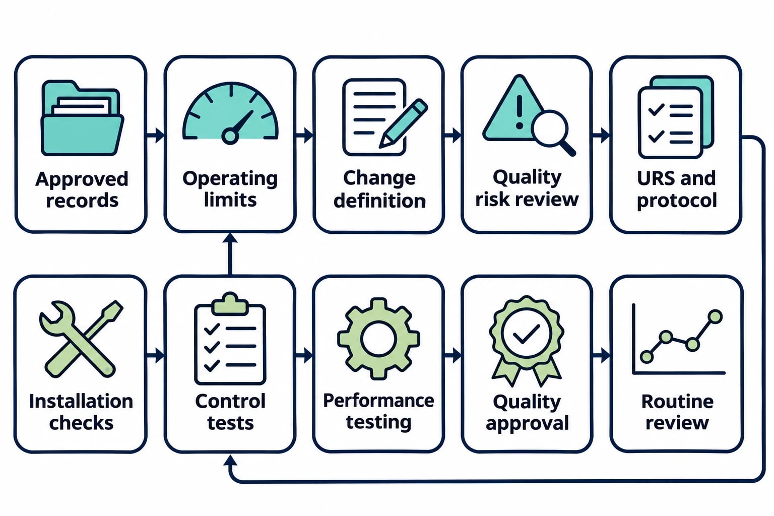
A repeatable GMP workflow keeps the energy case connected to the quality case from the first survey to routine operation.
1. Characterise the system and its current qualified state
Collect approved drawings, specifications, qualification records, calibration status, maintenance history, environmental data, utility trends and prior deviations. Establish the current operating limits before proposing a reduction.
2. Define the conservation measure and affected GMP controls
Describe the mechanical, electrical and control changes in enough detail for engineering, quality assurance and validation personnel to assess them. Identify the controls that protect product quality, the CCS elements involved and potential failure modes.
3. Perform documented quality risk assessment
Evaluate the impact on product quality, contamination control, qualification, calibration, maintenance, documentation and regulatory status. Annex 15 requires this assessment when determining the need for validation, verification or requalification.
4. Approve the design and test strategy
Create the user requirements, design review, protocol, acceptance criteria, sampling plan, data-review method and deviation route before installation. The test strategy should include normal operating conditions, defined operating limits and credible fault conditions.
5. Execute qualification and release through change control
Complete installation checks, calibration, control tests and performance testing. Record deviations, investigate failed criteria and obtain the required quality approvals before routine use.
6. Verify continued control and measured performance
Review energy consumption alongside the GMP controls affected by the project. For an HVAC change, that may include electrical demand, airflow, pressure differential, temperature, humidity, alarms and environmental-monitoring trends. For a utility project, it may include energy use, temperature, flow, quality results and maintenance findings.
Ongoing verification keeps energy savings inside the validated state
Qualification demonstrates that a revised system can meet defined requirements. Ongoing verification confirms that it continues to do so as filters load, seasons change, production patterns shift and maintenance takes place.
Facilities teams should review energy trends alongside quality indicators. A reduction in fan power has little value if pressure alarms, airflow deviations or environmental excursions increase. Stable quality performance with persistent excess energy use may identify a further risk-assessed optimisation opportunity.
This article reflects the independent analysis and editorial opinion of EnerTherm Engineering. Product names, trademarks, and brands mentioned belong to their respective owners. EnerTherm Engineering is not affiliated with, endorsed by, or a licensee of any third-party software or product mentioned unless explicitly stated.

Managing Director — EnerTherm Engineering
Dr. François Pierrel is Managing Director of EnerTherm Engineering with over two decades of expertise in thermal design, heat transfer, and industrial energy optimisation. He holds a PhD in Heat Transfer from Cranfield University and a Post-Doctorate from Heriot-Watt University.
