Why ISO 14644-16 Changes Energy Efficiency in Cleanrooms
How HVAC savings are assessed against airflow, pressure and GMP requalification
Energy efficiency in cleanrooms reduces the energy required to deliver a specified, validated cleanroom condition without weakening contamination control, product quality or operator safety.
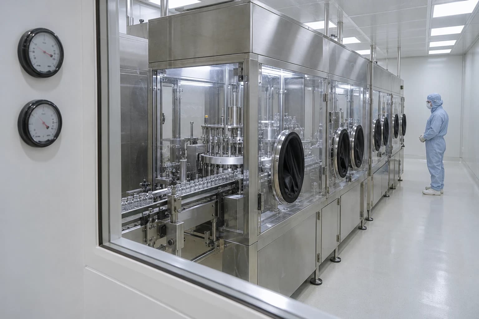
A Grade A filling zone cannot be treated like a conventional comfort-cooling load. Air must be filtered, distributed, conditioned and controlled to protect exposed product. Adjacent areas must retain the required pressure relationship. Operators, process equipment and heat loads can alter room conditions within minutes. These demands make HVAC one of the most energy-intensive services in a pharmaceutical facility.
BS EN ISO 14644-16:2019 changes the way facilities teams approach that energy use. The standard treats energy efficiency as a cleanroom performance issue rather than a separate utilities exercise. It covers new and existing cleanrooms, clean zones and separative devices across design, construction, commissioning and operation.
For UK pharmaceutical manufacturers, a lower fan speed or wider temperature band counts as an improvement only if the facility can demonstrate that particle control, airflow behaviour, pressure differentials, recovery performance and process conditions remain within qualified limits. The aim is to remove energy demand that does not support the validated process.
What BS EN ISO 14644-16:2019 changes for energy efficiency in cleanrooms
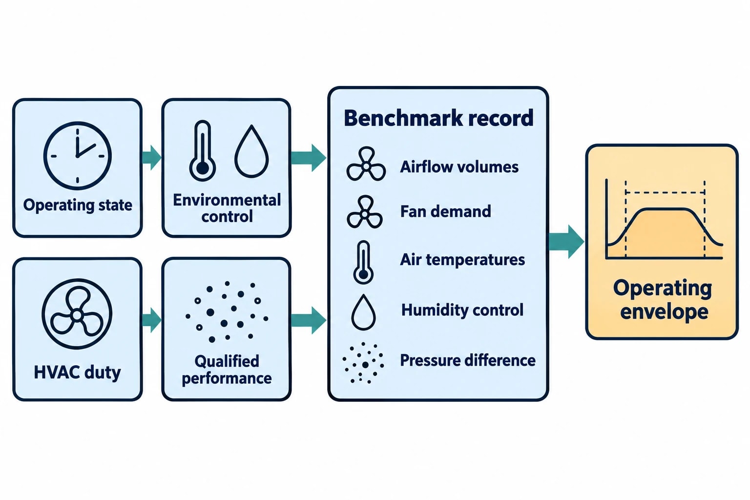
BS EN ISO 14644-16:2019 gives engineering and quality teams a framework for examining cleanroom energy use without separating it from cleanroom function. It introduces benchmarking to assess and compare energy performance while retaining the performance levels required by the ISO 14644 series.
A whole-site electricity trend is a poor guide to cleanroom efficiency. A production shutdown, batch change or lower ambient temperature may reduce consumption without proving that the HVAC system operates efficiently. Conversely, a room with high consumption may be performing exactly as its validated process requires.
Benchmark the controlled environment, not only the utility bill
A useful benchmark describes the cleanroom state driving energy demand. It can compare similar rooms, historic performance at the same facility or a calculated engineering reference. The comparator must account for the conditions that make rooms different.
Two Grade C rooms with equal floor area may have markedly different demand because of operating hours, heat gains, process equipment, outside-air intake, humidity requirements, filtration arrangements, occupancy or relationships with neighbouring rooms.
The baseline should record both energy and cleanroom performance:
- Air-handling unit supply, return and extract airflow volumes.
- Fan electrical demand, speed and static-pressure trends.
- Supply, return and extract-air temperatures.
- Outdoor-air condition and coil loading.
- Relative-humidity set points, actual values and control stability.
- Room pressure-difference trends, including door-opening events.
- Final-filter pressure drop and replacement history.
- Particle-classification, recovery and environmental-monitoring results.
- Production state, including at-rest, in-operation and approved setback periods.
This record gives the site a defensible reference point. It helps identify whether a high load arises from a justified process need, poor control, excessive airflow, fouled plant or an operating schedule that no longer reflects manufacturing activity.
Review historical overdesign with GMP evidence
Cleanroom overdesign is often inherited. A room may continue to operate at a historic airflow rate after a line change. An air-handling unit may run at a high fixed speed because no team has established its safe lower operating limit. A narrow humidity band may have become custom and practice without a documented link to product or process need.
ISO 14644-16 directs attention to the relationship between environmental requirements and design. This supports a structured review of whether the current cleanroom duty remains justified.
The room grade alone cannot answer that question. A lower airflow rate might be acceptable in one non-unidirectional Grade C room but unsuitable in an adjoining airlock, a Grade B background or an area supporting exposed sterile product. Facilities, production, engineering and quality teams need an agreed definition of the required operating envelope before changing HVAC duty.
Identify where your plant is losing energy and quantify the savings potential — our audits map every heat source, sink, and waste stream in your facility.
Why GMP performance sets the boundary for HVAC optimisation
Cleanroom HVAC consumes energy by moving, filtering, cooling, heating, dehumidifying and pressurising air. These functions interact. A change intended to save electricity can affect several critical attributes at once.
Reducing supply airflow can lower fan power, but it may also reduce room pressurisation, alter supply-air throw, lengthen recovery or change flow around operators and process equipment. Raising a supply-air temperature can reduce cooling demand while creating humidity-control instability during production. The engineering case must examine the complete controlled environment.
Pressure cascades are a defined energy constraint
EudraLex Volume 4, EU GMP Annex 1 has applied since 25 August 2023, except for point 8.123, which applied from 25 August 2024. It states that adjacent rooms of different grades should have an air-pressure difference of at least 10 Pa as a guidance value. It also states that filtered air should maintain positive pressure and/or airflow relative to the lower-grade background under all operational conditions, except where containment arrangements require another approach.
Pressure control depends on supply and extract balance, leakage paths, damper position, door activity and the behaviour of connected rooms. A single room-pressure sensor cannot establish whether an optimisation has preserved the full cascade. Engineers should review trends across the suite, particularly through shift changes, material transfers, cleaning activity and frequent airlock use.
Annex 1 requires critical pressure differences to be continuously monitored and recorded. A warning system must indicate air-supply failure or pressure reduction below defined limits. Any control reset must preserve alarm logic, delay justification, operator response and the rationale documented in the Contamination Control Strategy.
Containment can add a further condition. Facilities handling pathogenic, highly toxic, radioactive or live biological material may need modified pressure arrangements, including positively or negatively pressurised airlocks. Any reduction in extract duty or revised air balance needs an assessment of containment as well as product protection.
Airflow visualisation is engineering evidence
Annex 1 requires airflow patterns to be visualised to demonstrate that air does not enter a higher-grade area from a lower-grade area, and that air does not pass from less-clean areas, operators or equipment towards a higher-risk location. The studies must take place both at rest and in operation, including simulated operator interventions where appropriate. Video recordings must be retained.
This requirement changes how sites should treat fan-speed reductions and terminal-airflow adjustments. A smoke study completed before an HVAC reset does not validate the revised condition. Where airflow volume, room pressure, terminal distribution, process-equipment layout or operating practice changes, the original study may no longer represent routine manufacturing.
For unidirectional airflow systems, Annex 1 gives a 0.36 to 0.54 m/s guidance range at the working position unless the Contamination Control Strategy provides scientific justification for another value. The airflow visualisation study should correlate with the air-speed measurement. Grade A zones and their Grade B background therefore demand particular care during an energy project.
Which cleanroom energy measures fit ISO 14644-16?
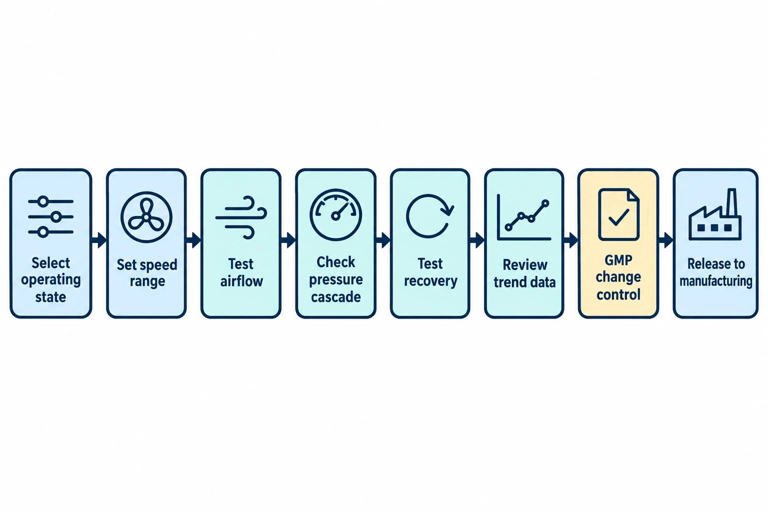
ISO 14644-16 does not prescribe a standard package of technologies. It frames the assessment of opportunities against feasibility, process compatibility, product quality, safety, regulations, cost, return, implementation timing, resources and business continuity.
The energy case and GMP change-control case need to support the same decision.
Airflow and fan optimisation
Variable-speed drives can reduce fan energy where airflow varies by validated operating state or where a system has excess static pressure. Before implementing a lower speed, the site should establish the safe minimum and maximum operating envelope. Final-filter loading, extract balance, airlock use, room pressure cascade and recovery must form part of that assessment.
Static-pressure reset can also reduce fan power where terminal units, dampers and sensors are correctly commissioned. Poorly configured resets can create unstable room pressure, damper hunting and simultaneous heating and cooling. Trend analysis should cover production, cleaning, door openings and shift changes rather than an unoccupied test period alone.
A planned setback during an unoccupied period is distinct from an uncontrolled overnight reduction. The procedure needs to define the authorised state, return-to-service sequence, recovery criteria, alarms and conditions for release back to manufacturing.
Temperature and humidity control
Annex 1 does not prescribe a universal temperature or relative-humidity set point for sterile manufacturing. This gives sites room for evidence-led optimisation, provided revised ranges meet product, process and personnel requirements.
Humidity control can be especially energy-intensive. The effect of a revised humidity target depends on outdoor-air volume, local climate, coil configuration, reheat strategy, internal heat gains and process constraints. Product stability, powder handling, electrostatic behaviour, operator comfort and microbiological-control strategy each need consideration.
Control bands matter as much as nominal set points. An excessively narrow temperature or humidity range can cause frequent heating, cooling, humidification or dehumidification with little process benefit. Quality approval, commissioning data and representative operational testing should support any revised control range.
Filtration, coils and heat recovery
Filter pressure drop increases fan duty over time. A final-filter replacement strategy should use qualified filters, differential-pressure data and contamination-control requirements rather than a generic calendar interval. Final-filter integrity testing forms part of Annex 1 periodic requalification.
Coil condition and valve operation also affect cleanroom energy performance. Fouling can increase air resistance and reduce heat transfer. A failed heat-recovery bypass damper can waste recovered energy or create unsuitable supply-air conditions. Trend data may reveal these faults through rising fan demand, drifting discharge-air temperature or prolonged coil-valve operation.
Heat recovery from exhaust requires a specific contamination-control assessment. The heat-exchanger arrangement, leakage risk, cleaning method and separation between supply and exhaust streams must be compatible with the process and the Contamination Control Strategy.

Identify where your plant is losing energy and quantify the savings potential — our audits map every heat source, sink, and waste stream in your facility.
Change control and requalification determine how savings proceed
Energy optimisation changes HVAC operating conditions. Annex 1 paragraph 4.32 makes the quality consequence explicit: cleanrooms and clean-air equipment require periodic requalification under defined procedures.
The minimum requalification scope includes particle classification, final-filter integrity testing, airflow-volume measurement and verification of air-pressure differences between rooms. It also includes air-velocity testing. For Grade B, C and D areas, the air-velocity test follows a risk assessment documented in the Contamination Control Strategy. In non-unidirectional airflow areas, recovery testing replaces velocity testing.
The maximum requalification interval is six months for Grade A and B areas and 12 months for Grade C and D areas. Annex 1 also requires appropriate requalification after remedial action for an out-of-compliance condition or after relevant equipment, facility or process changes. It identifies changes to HVAC operating parameters and final-filter replacement as changes to consider through change management.
Build the energy measure into the GMP record
A change-control package should document the current condition, proposed condition, quality-risk assessment, acceptance criteria, test plan and implementation sequence. It should identify the cleanroom attributes that the measure could affect.
The evidence package may include:
- Updated functional specifications where the HVAC control philosophy changes.
- A risk assessment linked to the Contamination Control Strategy.
- Revised drawings, control set points, alarms and operating procedures.
- Commissioning records for airflow, pressure, temperature and humidity.
- Airflow visualisation where the change could affect airflow pattern.
- Particle classification and, where applicable, recovery testing.
- Final-filter integrity results and room pressure-difference verification.
- Formal quality review before release to routine operation.
IQ, OQ and PQ documentation should reflect the scale and risk of the change. A controlled set-point adjustment has a different qualification burden from a revised air-handling unit, new terminal devices or ductwork modification. The common requirement is evidence that the revised system operates as intended in the manufacturing environment.
How an energy audit creates a cleanroom-specific evidence base
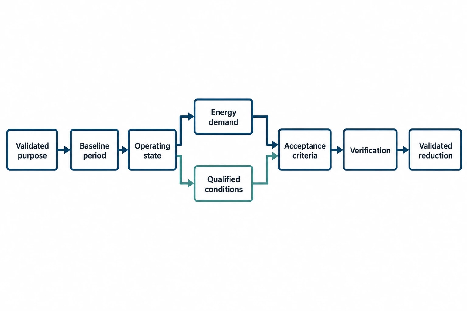
A pharmaceutical cleanroom energy audit should begin with the validated purpose of the room, not with a utility meter. The audit needs to separate energy that supports contamination control from energy that compensates for overcapacity, leakage, fouling, poor sequencing or an outdated schedule.
Measure energy and cleanroom condition together
Power data should be examined alongside supply and extract airflow, pressure difference, temperature, humidity, filter differential pressure and operating state. A reduction in electricity consumption during lower production does not prove that an HVAC change improved cleanroom efficiency.
The audit should also examine conditions that impose operational stress: door openings, material transfers, batch starts, cleaning, personnel entry and transition from setback to production. These conditions are most likely to expose weak pressure control or inadequate recovery.
Verify the result after implementation
Post-implementation verification should retain both energy and GMP indicators. The plan should define the baseline period, monitored variables, operating states, adjustment method, acceptance criteria and reporting frequency.
A credible result demonstrates lower energy consumption while maintaining qualified airflow volume, room-pressure differentials, temperature, humidity, recovery performance and relevant environmental-monitoring trends. This evidence allows engineering and quality teams to distinguish a validated reduction in demand from a temporary operational change.
ISO 14644-16 makes cleanroom efficiency a controlled engineering task
BS EN ISO 14644-16:2019 gives pharmaceutical facilities a disciplined route to improve energy efficiency in cleanrooms. It places benchmarking, technical assessment and documented implementation alongside the performance requirements that keep a cleanroom qualified.
The strongest projects target avoidable demand. They establish the safe operating envelope, test the effects on the pressure cascade and airflow pattern, and put the revised condition through GMP change control. A cleanroom that consumes less energy while retaining particle classification, airflow behaviour, pressure control, recovery performance and process conditions has delivered an improvement that engineering, facilities and quality teams can support.
This article reflects the independent analysis and editorial opinion of EnerTherm Engineering. Product names, trademarks, and brands mentioned belong to their respective owners. EnerTherm Engineering is not affiliated with, endorsed by, or a licensee of any third-party software or product mentioned unless explicitly stated.

Technical Manager — EnerTherm Engineering
John Naranjo is Technical Manager at EnerTherm Engineering, bringing specialist expertise in chemical and environmental engineering. He recently led the implementation of Omni Vision, EnerTherm's real-time energy and utility monitoring platform. He holds an MSc in Environmental Engineering from the University of Huelva and a BSc in Chemical Engineering, with memberships in both the Energy Institute and IChemE.
