Pharmaceutical Cleanroom Energy Efficiency: ISO 14644-16
How GMP sites can cut HVAC demand while preserving pressure cascades and compliance.
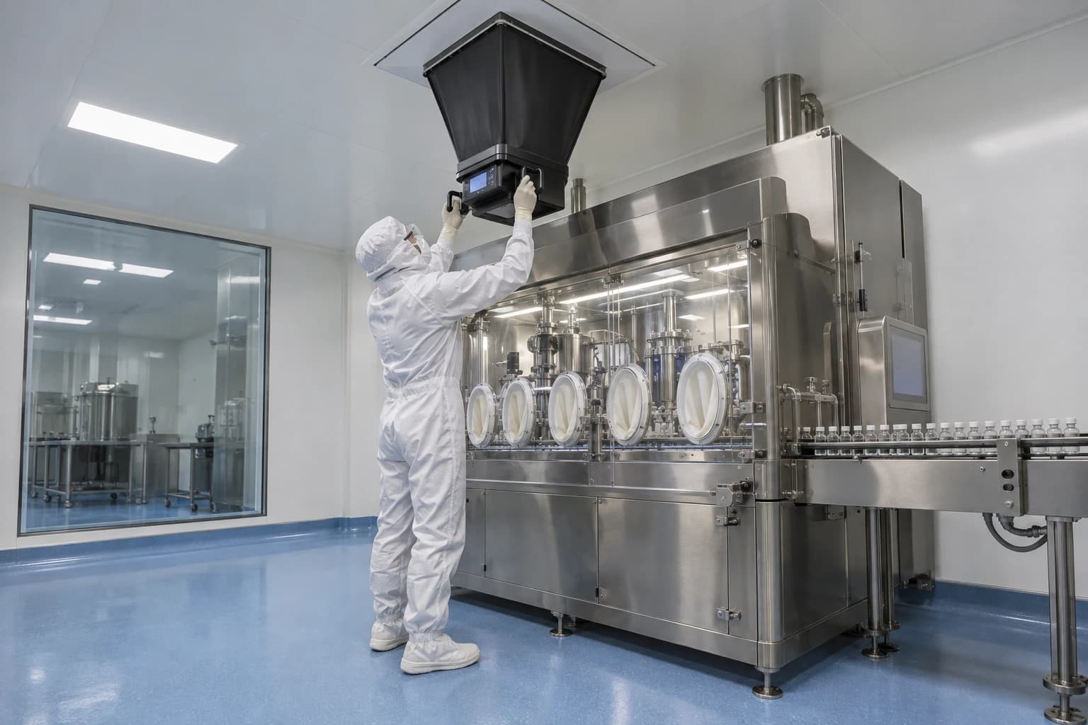
A pharmaceutical cleanroom energy-efficiency programme reduces the energy used to maintain clean air, pressure, temperature and humidity while retaining the suite’s qualified contamination-control performance.
ISO 14644-16:2019 provides cleanroom-specific guidance for this work. It addresses energy efficiency through design, construction, commissioning and operation while maintaining performance required by the ISO 14644 series. For pharmaceutical facilities, that qualification boundary matters more than any projected utility saving.
An HVAC setpoint change can alter supply airflow, room pressurisation, recovery time, relative humidity and air movement around exposed product. It therefore belongs within GMP change control, not a routine building-management adjustment. Effective projects establish the cleanroom’s required operating state, measure the energy needed to maintain it, then remove waste without weakening contamination control.
What ISO 14644-16 Means for Pharmaceutical Cleanroom Energy Efficiency
Energy efficiency is conditional on cleanroom performance
ISO 14644-16:2019 does not prescribe a universal air-change rate, fan speed or energy target. It gives recommendations for new and existing cleanrooms, clean zones and separative devices, and introduces energy benchmarking while maintaining ISO 14644 performance requirements.
A Grade A filling zone, Grade B background, Grade C preparation room and ISO 8 support area do not have equivalent risk profiles or HVAC needs. A single kWh per m² figure for an entire facility can conceal high fan energy in one critical suite or excessive conditioning in a lightly used support room.
The appropriate question is narrower: how much energy does a defined HVAC system consume to deliver a specified, qualified cleanroom condition over a known operating period?
A useful assessment defines:
- Cleanroom grade or ISO classification
- Product exposure and process risk
- Pressure relationships with adjacent rooms
- Temperature and relative-humidity limits
- Required airflow pattern and recovery performance
- Operating state, including at rest and in operation
- Environmental monitoring and alarm requirements
- HVAC plant boundary, including fans, coils, humidification and chilled-water pumps
This gives facility managers an engineering baseline that quality, production and maintenance teams can examine together.
Benchmark systems with comparable duties
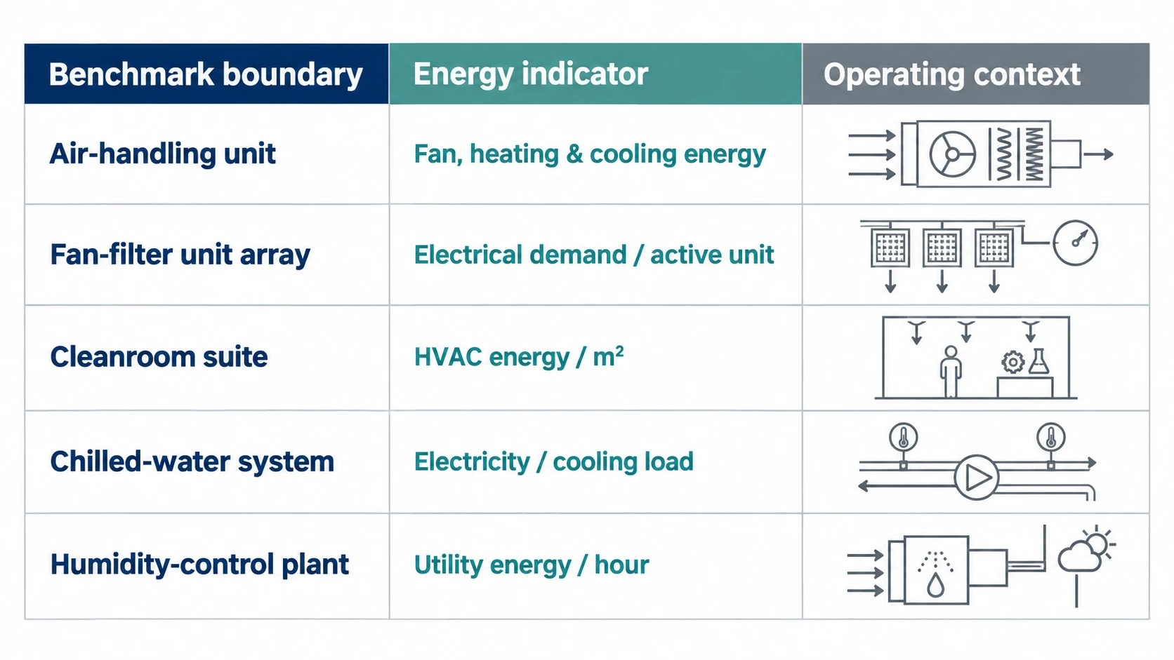
ISO 14644-16 frames benchmarking as a means of comparing cleanroom energy efficiency. The benchmark must include its boundary and operating context. Fan electricity from one air-handling unit cannot be compared directly with another unless airflow, operating hours, outside-air fraction, filter loading and room classification are known.
| Benchmark boundary | Energy indicator | Required context |
|---|---|---|
| Air-handling unit | Fan, heating and cooling energy | Supply airflow, outside-air fraction, operating hours and room states |
| Fan-filter unit array | Electrical demand per active unit | Airflow setting, filter pressure drop, coverage and operating state |
| Cleanroom suite | HVAC energy per m² | Grade, product exposure, occupancy, process equipment and setpoints |
| Chilled-water system | Electricity per delivered cooling load | Supply and return temperatures, pump operation and load profile |
| Humidity-control plant | Steam, gas or electricity per operating hour | Supply-air dew point, outdoor conditions and approved humidity limits |
A production week, an unoccupied week and a shutdown period require separate analysis. Combining them can make a setback programme appear successful even when normal production energy has not changed.

Identify where your plant is losing energy and quantify the savings potential — our audits map every heat source, sink, and waste stream in your facility.
GMP Boundaries for Cleanroom HVAC Optimisation
Annex 1 places air systems inside the contamination control strategy
EudraLex Volume 4, Annex 1, Manufacture of Sterile Medicinal Products, became applicable on 25 August 2023, except for point 8.123, which became applicable on 25 August 2024. It requires a contamination control strategy, or CCS, that identifies critical control points and assesses the combined effectiveness of technical, procedural and organisational controls.
HVAC is one of those controls. Annex 1 identifies premises, equipment, utilities, process validation, planned maintenance, monitoring and continuous improvement among the elements considered in the CCS. Energy work must assess how a change affects the whole control system, rather than treating supply-air volume or room pressure as isolated values.
For UK sites, MHRA GMP expectations remain central to inspection readiness. Facilities supplying EU markets must also ensure that their quality systems reflect applicable EudraLex requirements. The practical discipline is the same: document the rationale, assess risk, define acceptance criteria and retain evidence that the controlled state remains effective.
A CCS entry for an HVAC energy measure should identify the affected rooms, airflow paths, pressure relationships, product exposure, monitoring arrangements, alarm limits, requalification scope and restoration procedure.
Pressure cascades must remain demonstrably effective
Pressure differentials direct air from cleaner areas towards less clean adjacent areas where positive pressurisation is appropriate. Differential pressure alone does not prove effective contamination control. Door openings, personnel movement, material transfers, leakage paths, extract systems and local turbulence affect the actual airflow path.
Annex 1 requires pressure-difference indicators between cleanrooms, or between isolators and their background where relevant. Critical pressure differences should be continuously monitored and recorded, with a warning system for air-supply failure or a reduction below defined limits. Any alarm delay requires assessment and justification within the CCS.
The US Food and Drug Administration’s Sterile Drug Products Produced by Aseptic Processing, Current Good Manufacturing Practice recommends at least 10 to 15 Pa positive pressure between adjacent rooms of differing classification with doors closed. It also recommends continuous monitoring during each shift, frequent recording, alarm documentation and deviation investigation. This is US FDA guidance for aseptic processing under US current good manufacturing practice expectations, rather than a universal UK setpoint.
Each pharmaceutical facility should establish pressure targets from its own process risk assessment, design qualification and airflow evidence. Copying a differential pressure from a similar room elsewhere in the estate provides little assurance.
Airflow visualisation establishes the physical result
Annex 1 requires airflow-pattern visualisation to demonstrate that air does not ingress from a lower-grade area to a higher-grade area, and that air does not pass from less clean surfaces, operators or equipment towards higher-grade areas. Studies should cover both at-rest and in-operation conditions, including representative interventions.
Lowering fan speed may preserve a displayed pressure differential while changing the airflow path at an open door, pass-through or filling line. Smoke-study evidence should therefore form part of the acceptance criteria where the modification could affect directional airflow.
For unidirectional airflow systems, Annex 1 gives 0.36 to 0.54 m/s as a guidance range at the working position, unless the CCS scientifically justifies another value. This is not a target for all cleanrooms; it is a qualified operating parameter for systems that protect exposed product through unidirectional airflow.
How to Audit Pharmaceutical Cleanroom Energy Use
Establish actual operation before proposing changes
Historic setpoints often survive long after a process, room use or production pattern has changed. An area may run at full airflow overnight, at weekends or during extended campaign gaps because the original control sequence remains in place.
The audit should begin with evidence of actual performance:
- Room differential-pressure, temperature and humidity trends
- Supply, return, extract and outside-air flow measurements
- Fan speed, motor current and electrical demand
- Final-filter differential pressure and change history
- Chilled-water flow and supply-return temperatures
- Heating-coil and humidifier output trends
- Door-opening and material-transfer activity
- Environmental-monitoring excursions and pressure alarms
- Current qualification reports and airflow-visualisation studies
Power analysers can identify the electrical profile of supply and extract fans, fan-filter units, pumps and humidification equipment. Thermal imaging can assist investigation of failed insulation, hot motors, stuck valves and pipework losses. These observations should feed a controlled engineering assessment, rather than automatic control changes.
Separate at-rest and in-operation energy demand
Annex 1 defines the at-rest state as a completed installation with HVAC functioning, production equipment installed as specified but not operating, and no personnel present. The in-operation state has HVAC fully operational, equipment functioning in the defined mode and the maximum number of personnel performing or simulating routine work.
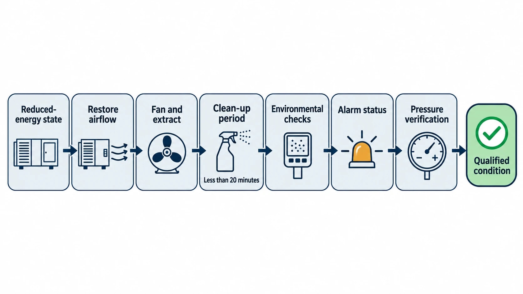
Every room should have a documented operating state for each period of the week, with associated fan, heating, cooling and humidification settings. A reduced-energy state should have a stated purpose and evidence that it remains suitable for the time it is used.
A cleanroom return-to-service procedure should specify:
- The trigger for restoring production airflow and conditioning.
- The required fan and extract sequence.
- The clean-up period and environmental checks.
- The alarm status and pressure verification required before release.
- The actions if the room does not return to its qualified condition.
Annex 1 gives a clean-up period of less than 20 minutes as guidance, while requiring each facility to determine, document and follow its own period during qualification. A reduced-flow strategy must allow sufficient time and verified performance before exposed-product activity resumes.

Identify where your plant is losing energy and quantify the savings potential — our audits map every heat source, sink, and waste stream in your facility.
HVAC Measures That Can Reduce Energy Without Compromising GMP
Reduce airflow only within a qualified operating envelope
Fan power is a major component of cleanroom HVAC electricity demand. Energy reduction may be available in at-rest or unoccupied periods, particularly where rooms retain full production airflow for operational convenience rather than a documented quality need.
The change requires more than reducing a variable-speed-drive setpoint. The facility must demonstrate that the revised state maintains the required pressure-cascade direction, airflow pattern, temperature, humidity and recovery performance. It must also show that the system restores correctly before production begins.
The qualified minimum flow should be specific to the room, state and process. A Grade B background supporting aseptic processing requires a different assessment from an ISO 8 room used for lower-risk activity.
Address filter and air-path pressure losses
Rising filter differential pressure increases the fan pressure required to deliver a set airflow. High demand may result from expected final-filter loading, but it can also indicate poor prefiltration, fouled coils, blocked ductwork, damper faults, unsuitable filter selection or an airflow setpoint above the qualified requirement.
An air-path review should cover outside-air intake, prefilters, cooling and heating coils, fan condition, ductwork, terminal devices, HEPA housings, return paths and extract balance. The goal is to identify the mechanism behind excess pressure loss before changing fan control.
Variable-speed drives can improve part-load performance, but supply and extract control must respond together. A supply-air reduction without appropriate extract control can weaken or reverse a pressure cascade. Commissioning should include representative door-opening and transfer activity, rather than a quiet-room test alone.
Correct simultaneous cooling and reheating
Humidity control often requires cooling to remove moisture followed by reheating to meet supply-air temperature. That sequence can be necessary. It can also reveal a control problem, including a heating-valve leak, excessive outside air, poorly coordinated coil loops or an unnecessarily narrow humidity specification.
Engineering teams should review supply-air dew point, chilled-water valve response, heating-coil valve shut-off, humidifier behaviour, outdoor-air treatment and seasonal room data. The process should distinguish between energy required to meet an approved moisture limit and energy caused by conflicting controls.
A wider approved temperature or relative-humidity band may reduce conditioning energy. Quality risk assessment must consider product stability, operator comfort, electrostatic risk, process performance and material handling before any limit changes.
Assess heat recovery at the contamination boundary
Heat recovery can reduce the heating or cooling load associated with outside air. Pharmaceutical applications require a design assessment that addresses air-stream separation, leakage risk, cleanability, maintenance access, pressure relationships and long-term integrity.
Run-around coil arrangements transfer heat between air streams through a pumped fluid loop without direct air mixing. They may suit applications where direct recovery devices would create an unacceptable cross-contamination concern. The selected arrangement must be assessed against the CCS and supported through design qualification.
Qualification, Requalification and Change Control
Define evidence before implementation
Changes to fan setpoints, pressure alarms, setback schedules, damper positions, supply-air temperature, dew point or air-handling sequences can alter a qualified system. The change-control package should describe the energy objective, engineering basis, risk assessment, testing protocol, acceptance criteria, roles and required approvals.
The evidence should connect to current controlled documents, including the CCS, HVAC drawings, functional specifications, alarm-response procedures, standard operating procedures and maintenance plans.
Annex 1 identifies a relevant qualification set for cleanrooms and clean-air equipment: final-filter integrity, airflow volume or velocity, pressure difference, airflow direction and visualisation, airborne and surface microbiology, temperature, relative humidity, recovery and containment leakage where applicable.
Apply IQ, OQ and PQ proportionately
Installation qualification can verify that new meters, drives, dampers, sensors or control hardware are installed and calibrated correctly. Operational qualification can test alarms, interlocks, fan response, pressure control and restoration from reduced-energy operation.
Performance qualification should demonstrate that the room retains its intended performance under representative conditions. Depending on risk, that can include classification, airflow visualisation, recovery testing, pressure mapping and review of environmental-monitoring data.
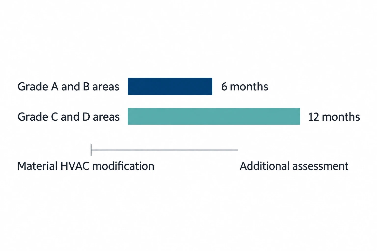
Annex 1 requires requalification at intervals no greater than six months for Grade A and B areas and 12 months for Grade C and D areas. A material HVAC modification can require additional assessment before the routine interval. The quality function should define that requirement in the change plan.
Energy Inspections and Ongoing Verification
UK air-conditioning inspection duties can identify opportunities
The Energy Performance of Buildings (England and Wales) Regulations 2012 apply to air-conditioning systems with an effective rated output above 12 kW. Regulation 17 requires relevant systems to be inspected at intervals no greater than five years, while Regulation 18 sets out the inspection-report requirement.
The regulations cover systems that combine temperature control with ventilation, humidity control or air cleanliness. Pharmaceutical air-conditioning infrastructure may therefore fall within scope. The inspection report assesses efficiency and system sizing against cooling requirements, and provides advice on cost-effective improvement.
A statutory inspection does not replace GMP qualification. It can identify opportunities that warrant a separate feasibility study, change-control assessment and defined requalification programme.
Measure energy and cleanroom control together
Savings require continuing verification after project handover. An effective monitoring plan pairs utility data with cleanroom performance indicators, so that an energy reduction does not obscure an emerging control issue.
Useful paired measures include fan electricity against supply airflow, cooling energy against supply-air temperature, humidification demand against supply-air dew point, and fan speed against filter differential pressure. These trends should sit alongside pressure alarms, room-state transitions, environmental-monitoring results and production schedules.
A credible energy baseline identifies the HVAC boundary, measurement period, operating states, weather influence and material-production changes. The resulting evidence gives engineering and quality teams a common basis for deciding whether a measure has reduced energy intensity while preserving the qualified cleanroom condition.
This article reflects the independent analysis and editorial opinion of EnerTherm Engineering. Product names, trademarks, and brands mentioned belong to their respective owners. EnerTherm Engineering is not affiliated with, endorsed by, or a licensee of any third-party software or product mentioned unless explicitly stated.

Managing Director — EnerTherm Engineering
Dr. François Pierrel is Managing Director of EnerTherm Engineering with over two decades of expertise in thermal design, heat transfer, and industrial energy optimisation. He holds a PhD in Heat Transfer from Cranfield University and a Post-Doctorate from Heriot-Watt University.
