Why P&ID Simulation Validation Must Precede Modifications
An 11-step check reconciles control loops, trips and heat duties with plant records.
P&ID simulation validation is the documented process of proving that a process model represents the as-built plant, operating data, control philosophy and protective functions before engineers use it to justify a modification.
A distillation model may suggest that more reboiler duty, a larger reflux pump or a new feed location will lift throughput. Tray temperatures settle, product purity remains within specification and calculated flooding stays below the selected limit. The calculation looks persuasive.
The operating plant may contain a steam-pressure constraint, a condenser bypass, a reflux cascade loop, a high-pressure trip or an exchanger fouling margin absent from the model. Each changes the answer. A modification based on an unvalidated case can shift the bottleneck, compromise operating flexibility or create an unsafe process response.
For UK petrochemical, speciality chemical and fine chemical plants, P&ID simulation validation belongs at the start of troubleshooting, debottlenecking and modification work. It connects Aspen Plus, Aspen HYSYS or DWSIM models to evidence from controlled P&IDs, operating logs, laboratory results, equipment records and control documentation. The resulting model gives operations, projects and process-safety teams an engineering basis they can examine.
What P&ID simulation validation establishes

A simulation can converge with internally consistent calculations while representing the wrong plant. Thermodynamic packages, recycle convergence methods and equipment models produce useful results only when the configuration and operating assumptions reflect reality.
The P&ID defines the installed process
A process flow diagram identifies the main equipment and streams. A piping and instrumentation diagram adds the detail that determines plant behaviour in service, including:
- Equipment tags, line numbers, isolation points and alternate routes
- Control valves, bypasses, recirculation lines and relief connections
- Transmitters, controllers, indicators, alarms and shutdown valves
- Steam, condensate, cooling water, thermal oil, nitrogen and instrument-air connections
- Interlocks, permissives, trips and valve fail positions
- Sampling points, drains, vents and start-up arrangements
A steady-state model may represent a heat exchanger as a duty block. The P&ID may show a bypass around the process side, a steam pressure-control valve, a condensate arrangement and a low-flow trip. These details determine whether the calculated duty is available, controllable and maintainable across the intended operating range.
Validation uses a defined operating period
Engineers should compare the model against data from a specific, stable operating period. Feed composition, production rate, utility conditions, laboratory results and historian records must relate to the same process state.
Weekly averages often combine incompatible conditions. A speciality chemical unit may change grade, solvent content, batch phase or production rate several times in a week. A model calibrated against blended averages can match no real operating condition.
The comparison should cover material flow, composition, temperature, pressure, utility use and product quality. Dynamic validation adds evidence about the direction, speed and limits of plant response during a suitable disturbance, such as a feed-rate change, cooling-water temperature shift or reflux adjustment.
| Validation area | Evidence to reconcile | Engineering question |
|---|---|---|
| Process configuration | As-built P&IDs, line lists, equipment register | Does the model contain the installed routes, bypasses and recycles? |
| Operating basis | Historian trends, batch records, shift logs, laboratory data | Does one consistent data window define the model case? |
| Equipment performance | Datasheets, inspection findings, maintenance records | Do duty, pressure drop, pump performance and fouling assumptions match service? |
| Control behaviour | Loop sheets, control narratives, alarm schedules, cause-and-effect charts | Does the dynamic model represent the real control and protective response? |
| Feed properties | Feed assays, water content, product analyses | Does the thermodynamic method predict observed phase behaviour? |

Map every energy and material flow in your process with detailed heat and mass balance calculations — the foundation for any optimisation or design project.
Why an unvalidated model creates modification risk
Modification studies usually begin with a sound commercial or technical objective: increase throughput, improve yield, reduce steam demand or resolve an operating constraint. Unverified assumptions can turn that objective into a poor capital decision.
Heat and mass balances can hide the real bottleneck
A model may predict that an exchanger has enough area to supply the required duty. Plant data may show a different condition: fouling has increased resistance, the utility header cannot maintain pressure, or an operator keeps a bypass partly open to control downstream temperature.
The same issue occurs in separation systems. A model may indicate spare tray hydraulic capacity in a column while the actual production limit lies in condenser duty, reflux-pump head, reflux-drum level control, compressor capacity or cooling-water availability.
A validated balance identifies the active constraint. An unvalidated balance can direct investment towards equipment that was never limiting the plant.
Thermodynamic selection needs plant evidence
The selected fluid package determines phase split, enthalpy, density, vapour-liquid equilibrium and calculated heat duty. Process engineers commonly assess NRTL or UNIQUAC for strongly non-ideal liquid systems, while SRK and Peng-Robinson are frequently assessed for hydrocarbon and gas-processing duties. Component data, operating pressure, temperature range and available interaction parameters affect the choice.
Validation tests the method against process evidence. For a distillation train, this may include measured temperatures, pressures and product compositions. For liquid-liquid separation, it includes observed phase split and composition. For reactive systems, it includes conversion, selectivity and reactor heat removal.
Engineers should record deviations rather than adjust uncertain parameters until a model matches a target value. A mismatch may indicate poor measurement quality, an omitted operating route, equipment degradation, incomplete property data or a process limitation requiring further investigation.
Control assumptions determine dynamic results
Control loops determine chemical-plant operating behaviour. A dynamic model that assumes a temperature controller moves a steam valve directly can mislead where the plant uses cascade control, valve-position limits, analyser feedback or frequent operator intervention.
Validation should confirm:
- The controlled and manipulated variables for each material loop.
- The control arrangement, including whether it is single-loop, cascade, ratio, split-range, override or manual during normal operation.
- Normal setpoint range, controller mode and practical output limits.
- Valve characteristics and fail position following loss of air or power.
- Signal location, filtering and response delay.
- Routine operator actions that affect the response.
A reactor can appear stable in simulation because the cooling valve opens immediately and without limit. The P&ID and control narrative may show that cooling depends on a shared header, a low-flow permissive or a shutdown action. The model must reproduce these installed constraints before it assesses a higher feed rate, concentration or batch temperature.
Trips and alarms define the operating boundary
High-high level trips, high-pressure shutdowns, low-flow alarms and emergency isolation actions affect inventories, flows, heat release and the route to a safe state. They are process constraints, not drawing annotations.
HSE guidance on control systems describes a lifecycle under BS IEC 61508 that includes hazard and risk evaluation, specification, design, validation, installation, commissioning, operation, maintenance and modification. HSE also warns that non-safety process control should not create demand on protective systems beyond the demand anticipated in their design.
A dynamic model should be checked against the P&ID, cause-and-effect chart, alarm schedule, loop documentation and operating procedure before an upset case is run. It should represent approved trip setpoints and actions where relevant to the study. It should never redefine safety-instrumented-function requirements or stand in for a hazard study.
P&ID validation and COMAH management of change
The Control of Major Accident Hazards Regulations 2015 apply to establishments within scope in England, Wales and Scotland. Regulation 7 requires operators to implement their major-accident-prevention policy through a safety management system. Schedule 2 requires that system to address management of change, including procedures for planning modifications to installations, processes or storage facilities.
A validated model supports that work by providing a defined technical baseline. It does not replace formal management of change, HAZOP, safety review, safety-report duties or independent safeguards assessment.
Regulation 6 and Regulation 10 have separate roles
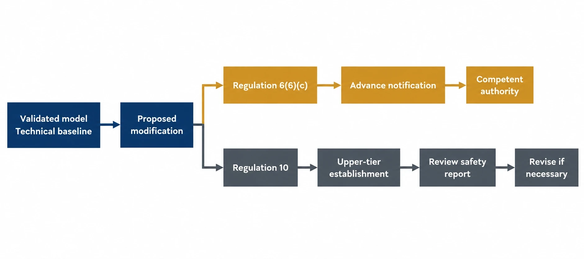
Regulation 6 concerns notification of an establishment. Regulation 6(6)(c) requires an operator to notify the competent authority in advance of a modification of the establishment or an installation that could have significant consequences for major-accident hazards.
For upper-tier establishments, Regulation 10 has a different function. It requires the operator to review and, where necessary, revise the safety report following specified trigger events, including modification of an establishment, installation, storage facility or process. Both obligations can be relevant to a change, but they should not be treated as the same requirement.
The modification team needs an agreed description of the plant as it operates before it uses model results to support the safety and engineering review.
Control and safeguard evidence needs reconciliation
HSE’s COMAH control and instrumentation assessment guidance states that much of the information expected in a full BS EN IEC 61511 lifecycle is also required for COMAH demonstrations. The guidance also identifies the need for a documented procedure for safety-instrumented-system modification.
Before proposing a process or controls change, the study should reconcile:
- Current P&IDs against equipment and field configuration
- Cause-and-effect charts against the actual trip actions
- Alarm schedules against normal operating limits and operator response
- Loop sheets against controller configuration and valve action
- Proof-test, maintenance and calibration records against instrument availability
- Operating procedures against routine bypasses, temporary arrangements and start-up practice
A discrepancy needs a recorded disposition. The team may update the model, correct the drawing, obtain more data or escalate the issue through the site’s management system. Unresolved discrepancies should remain visible in the model-validation record.

Map every energy and material flow in your process with detailed heat and mass balance calculations — the foundation for any optimisation or design project.
An 11-step P&ID simulation validation workflow
EnerTherm Engineering’s 11-step heat and mass balance methodology provides a structured route from plant evidence to a decision-ready model. The detailed sequence should align with the site’s management-of-change arrangements.
Define the basis before building the model
-
Set the study question. State whether the decision concerns throughput, yield, exchanger duty, reactor cooling limit, column bottleneck or another defined issue.
-
Establish the model boundary. Include upstream, downstream, recycle, storage and utility systems where they materially affect the answer.
-
Create an as-built P&ID register. Mark model items as confirmed, uncertain, omitted or outside scope. Site walkdowns help resolve conflicts between drawings and operation.
-
Select representative data windows. Choose stable periods with aligned process historian data, laboratory results, feed records and utility conditions.
Reconcile physical and thermodynamic behaviour
-
Build the component and property basis. Select and document the thermodynamic method, component data and phase-equilibrium assumptions.
-
Reconcile mass balance. Compare feed, product, recycle, purge, losses and composition data before accepting calculated duties.
-
Reconcile energy and pressure behaviour. Check exchanger temperatures, utility flow, condenser and reboiler loads, reactor heat removal, pressure drop and product specifications.
-
Assess equipment condition and capacity. Use maintenance, inspection and performance records to test fouling, pump head, valve authority, heat-transfer performance and hydraulic assumptions.
Validate the operating response and document limits
-
Model the applicable controls. Represent validated inventories, valves, controller configuration, operating limits and relevant process-control interactions.
-
Test credible disturbances. Compare model response with suitable plant trends, then assess proposed modification cases against site-defined scenarios.
-
Issue the validation register and operating basis. Record data sources, assumptions, deviations, uncertainty, model version and constraints that limit the proposed change.
This sequence prevents a model becoming a collection of convenient defaults and creates an audit trail for engineering review.
What a decision-ready model should deliver
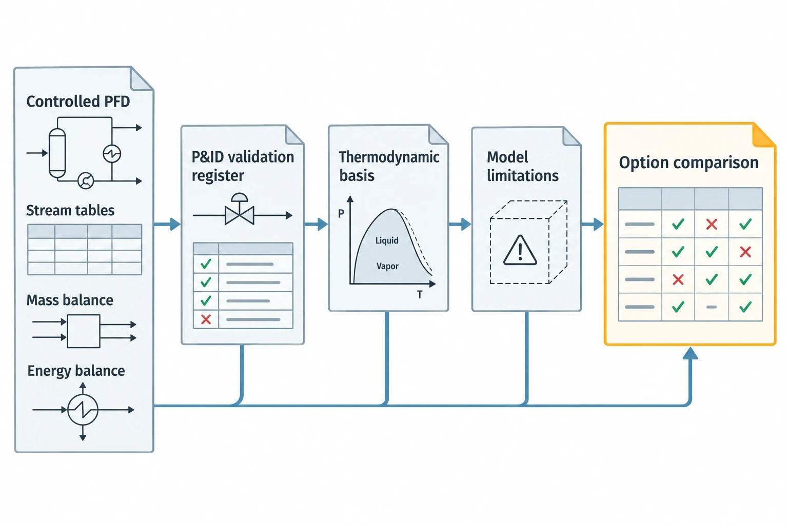
The final deliverable should include a controlled PFD with stream tables, reconciled mass and energy balances, a P&ID validation register, the selected thermodynamic basis and a statement of model limitations.
For a distillation project, the package might show product-quality sensitivity to feed composition, condenser duty, reflux limits and column pressure. For an exothermic reactor, it might identify the relationship between feed rate, heat removal, temperature control and the applicable protective response. For an exchanger project, it should distinguish design duty from the duty currently available in service.
This allows modification teams to compare options on a common basis and prevents a calculated improvement being mistaken for an installed capability.
Validate the plant before changing it
The modification should follow a validated representation of the plant, supported by traceable evidence and clear operating limits.
This article reflects the independent analysis and editorial opinion of EnerTherm Engineering. Product names, trademarks, and brands mentioned belong to their respective owners. EnerTherm Engineering is not affiliated with, endorsed by, or a licensee of any third-party software or product mentioned unless explicitly stated.

Senior Process Engineer — EnerTherm Engineering
Masab Javed is a Senior Process Engineer at EnerTherm Engineering with extensive expertise in chemical process design, decarbonisation, and sustainable industrial solutions. He holds an MSc from TUM School of Management and a BEng in Chemical Engineering from NUST, with experience spanning ammonia production, CO2 capture, and semiconductor manufacturing optimisation.
