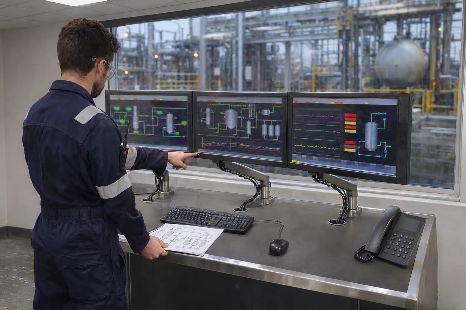
Chemical Process Simulation Services for COMAH Changes
Validated models support COMAH management of change and upset-case assessment.
Chemical process simulation services create validated mathematical models of process plants to predict material flows, phase behaviour, energy duties, equipment performance and operating limits. Under Regulation 10 of the Control of Major Accident Hazards Regulations 2015, SI 2015/483, an upper-tier operator must review and, where necessary, revise its safety report before modifying an establishment, process, or the nature, physical form or quantity of dangerous substances where the change could significantly affect major-accident hazards.
That requirement puts the heat and mass balance at the centre of change assessment. A proposed throughput increase, solvent substitution, recycle revision or heat-recovery project can alter inventories, vapour generation, relief loads, waste-gas composition and the performance margin of existing safeguards.
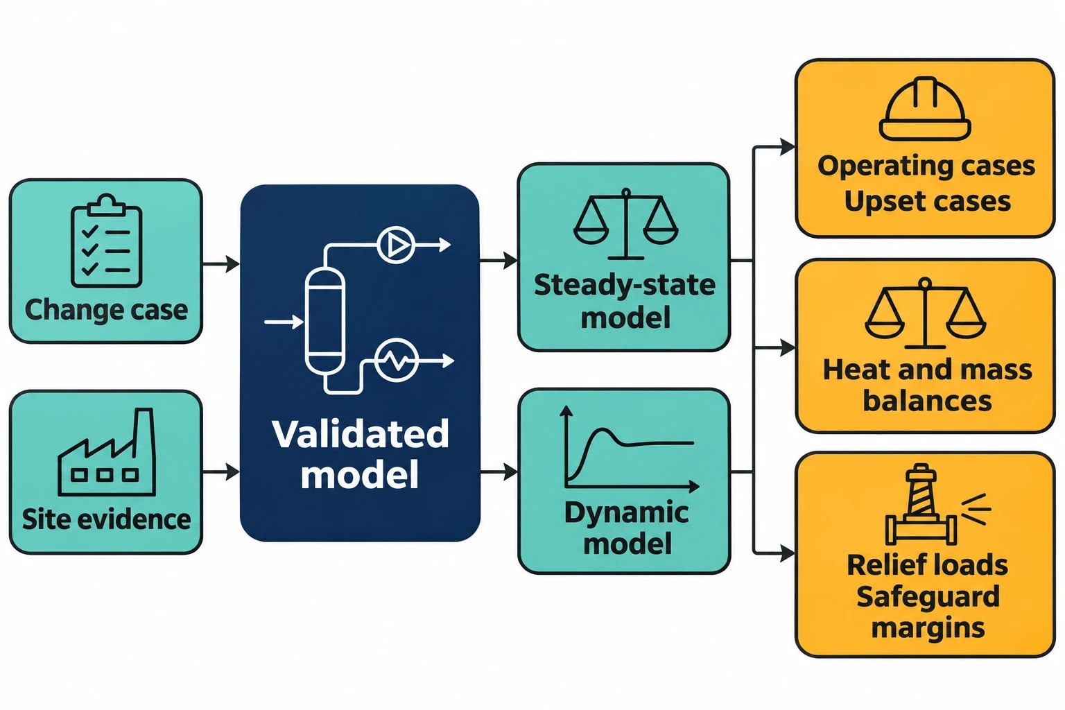
A converged flowsheet alone is insufficient. The model must represent the plant as operated, use thermodynamic methods suited to the chemistry, and agree with credible site evidence. It must then test the operating and upset cases relevant to the modification.
Why COMAH Changes Need Chemical Process Simulation Services
COMAH applies where dangerous substances are present at or above the Schedule 1 thresholds. Upper-tier operators must prepare a safety report describing the establishment, processes, dangerous substances, major-accident scenarios and measures used to prevent or limit their consequences.
HSE expects a clear connection between identified hazards and the measures used to manage them. Safety reports must also demonstrate that safeguards protect plant against foreseeable excursions beyond design conditions.
Management of change starts with the physical change
A management-of-change review needs more than a revised process flow diagram. It needs quantified answers to practical questions.
A feedstock change may move a distillation column closer to flooding by increasing vapour traffic. A higher reactor temperature may increase cooling demand and change vent-stream composition. A new exchanger may reduce steam use while reducing the driving force available during low-rate operation. A smaller purge may improve raw-material yield but permit inerts or impurities to accumulate in a recycle loop.
Chemical process simulation services connect these effects in a consistent calculation framework. A validated steady-state model establishes stream flows, compositions, temperatures, pressures, phase fractions and enthalpies. A dynamic model can then assess the path between operating states when utilities fail, feed properties shift, controllers respond or trips activate.
What a model can contribute to a safety report review
Simulation does not replace HAZOP, layers-of-protection analysis, relief-system design, functional-safety work or operating procedures. It provides the process data these activities require.
Useful questions include:
- What vapour flow and composition reach the flare header after condenser-duty loss?
- Does a proposed feed increase exceed reactor-jacket heat-removal capacity?
- How quickly does reactor temperature rise after loss of cooling water?
- What liquid inventory transfers to a separator during a high-level trip?
- Does a solvent change create liquid-liquid separation, carryover or an azeotropic limitation?
- How do compressor outage and recovery alter recycle composition and purge demand?
- Does a waste-gas treatment system receive a higher short-duration load than under normal operation?
The model should define what it can and cannot answer. A steady-state column model built to investigate product quality may not include the vessel holdup, control logic or relief connections needed for a transient upset assessment.

Map every energy and material flow in your process with detailed heat and mass balance calculations — the foundation for any optimisation or design project.
Building a Defensible Heat and Mass Balance
A future-state calculation has little value if the current-state model does not represent the plant. External simulation support is particularly useful where P&IDs, historian records, laboratory analyses, design documentation and operator observations do not agree.
Establish a controlled modelling basis
The modelling basis should identify the intended decision, process boundary, unit operations, feed cases, utility conditions, design constraints and scenarios to be examined. It should distinguish measured values from estimates and assumptions.
For a petrochemical, speciality chemical or fine chemical facility, the evidence pack commonly includes:
- Current PFDs, P&IDs and control narratives
- Equipment datasheets and operating limits
- Feed assays, product specifications and laboratory results
- Historian trends for flow, pressure, temperature, level and utility consumption
- Batch records and campaign data where relevant
- Known performance problems, including fouling, flooding, instability and off-spec product
- Planned modification details and credible abnormal operating cases
- Relevant flare, vent, relief and abatement information
A clear basis prevents a common error: applying a design condition to a plant whose normal feed quality, fouling state and utility performance have changed over time.
Select thermodynamics for the actual fluid system
Thermodynamic package selection determines whether calculated phase splits and duties have engineering meaning. The selected method must suit composition, pressure, temperature and the available property data.
NRTL and UNIQUAC are commonly used for highly non-ideal liquid systems, including many aqueous-organic, alcohol, ester and solvent mixtures. Peng-Robinson and Soave-Redlich-Kwong methods are widely used for hydrocarbon and gas-processing duties. Systems involving liquid-liquid equilibrium, vapour-liquid-liquid equilibrium, electrolyte behaviour or azeotropes often need more detailed property assessment.
Process engineers typically select Aspen Plus, Aspen HYSYS or DWSIM according to the process duty, existing site model base and required analysis.
Validate against several independent plant measures
A model should be tested against more than total mass flow. A good apparent mass closure can still conceal incorrect component splits, reaction conversion or heat loss.
| Validation check | Engineering purpose |
|---|---|
| Feed and product flow closure | Identifies missing streams, measurement error and unaccounted losses |
| Product assay comparison | Tests component-level predictions |
| Column temperature profile | Tests vapour-liquid equilibrium and pressure representation |
| Reboiler and condenser duty | Tests energy balance and utility assumptions |
| Reactor outlet temperature | Tests reaction heat, conversion and cooling duty |
| Recycle composition and purge flow | Tests accumulation and inert control |
| Measured pressure drop | Tests hydraulic assumptions and capacity conclusions |
There is no universal COMAH percentage tolerance for model agreement. The acceptance criterion should relate to the decision. A model assessing a 5% feed-rate increase must resolve the margin to the relevant hydraulic, thermal or inventory limit with greater confidence than a model used for preliminary screening.
Recycle Loops and Separation Changes Need More Than a Design Case
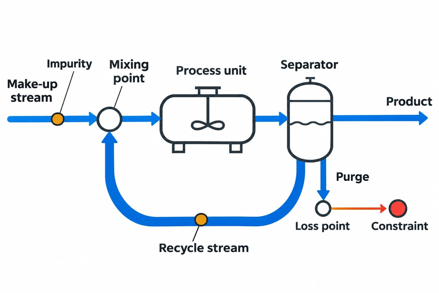
Recycle loops often create the largest gap between a nominal flowsheet and plant behaviour. Solvent recovery, hydrogen recycle, mother-liquor recycle, reflux circuits and off-gas recycling can accumulate components that enter at low concentration.
Converged does not mean representative
A solver can converge on a mathematical solution that does not reflect plant operation. A credible recycle study identifies the make-up stream, recycle stream, purge, intended loss points and unintended losses. It then tracks the components most likely to accumulate.
That analysis can reveal an impurity increase that changes vapour pressure, corrosion exposure, distillation separation, product quality or flare composition. It can also show that a lower purge rate has an economic benefit only until the recycle composition reaches a defined constraint.
Separation studies should test operating range
Distillation and liquid-liquid separation should be assessed across expected feed composition, throughput and utility conditions. A single normal operating point cannot establish a column’s performance during reduced reflux, elevated condenser temperature, fouling or altered feed volatility.
For a proposed capacity increase, the key output may be predicted vapour and liquid loading at each limiting tray or packing section. For a solvent-replacement project, it may be a revised liquid-liquid split, entrainment risk or composition reaching downstream recovery equipment. The engineering decision should rest on the limiting condition, not the most favourable case.
When Dynamic Simulation Adds Value to COMAH Assessment
Steady-state simulation establishes the condition a process can sustain. Dynamic simulation examines the response over time. This distinction matters where consequence depends on holdup, heat release, controller action, shutdown response or utility availability.
Test credible disturbances and protective actions
Dynamic models can represent vessel inventories, compressors, control valves, heat-transfer equipment, controllers, interlocks and utility failures. Suitable scenarios include loss of cooling water, loss of reflux, sudden feed-composition change, compressor trip, agitator failure and utility-pressure decay.
For an exothermic reactor, the model can calculate the temperature trajectory following a coolant-flow reduction and compare the predicted time to a trip set point with the documented detection, control and shutdown response. For a distillation system, it can estimate how a reflux interruption changes overhead pressure, condenser duty and vapour composition delivered to downstream recovery or abatement equipment.
The model output must state its basis. Initial inventory, heat-transfer coefficient, reaction kinetics, controller tuning, alarm set points, valve travel and trip logic can materially alter the result.
Define operating envelopes, not arbitrary targets
Simulation can establish quantified process limits that support operating procedures and change decisions. Examples include:
- Maximum feed rate before available reactor cooling becomes limiting
- Minimum reflux ratio that maintains product specification
- Maximum inert concentration in a recycle loop
- Minimum condenser duty that keeps overhead pressure below its operating limit
- Maximum short-duration waste-gas flow sent to an abatement system
- Maximum exchanger pressure drop before pump or compressor constraints arise
Those limits remain inputs to the wider safety case. The project team must confirm instrument performance, alarm response, relief capacity, equipment integrity and operator actions through the relevant engineering disciplines.
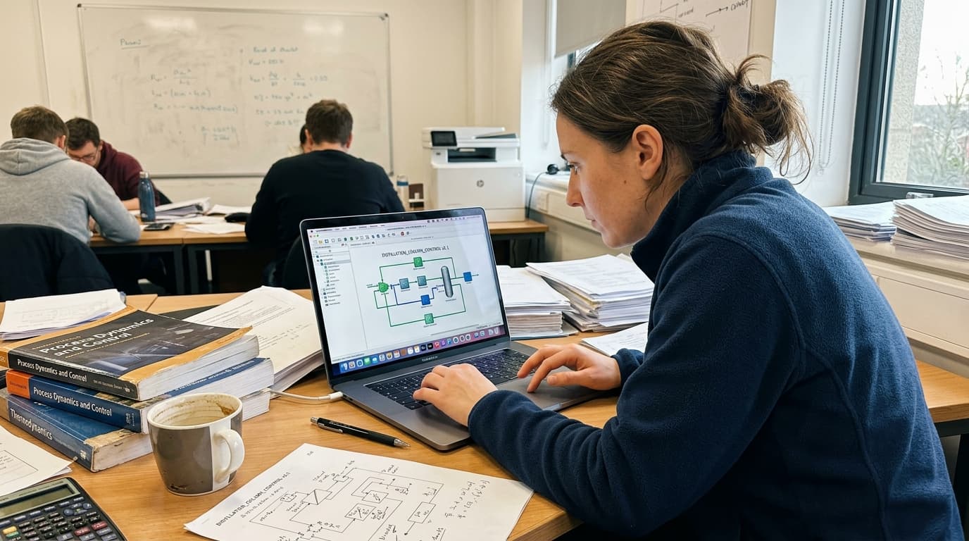
Map every energy and material flow in your process with detailed heat and mass balance calculations — the foundation for any optimisation or design project.
Chemical Process Simulation Services for Energy and CO₂ Reduction
A heat-recovery project needs a plant-wide heat and mass balance. Savings claimed from one exchanger can disappear if the modification increases refrigeration, cooling-water use, pumping duty, flare demand or treatment load elsewhere.
A quantified heat-recovery illustration
Consider an illustrative continuous process with 2 MW of recoverable hot-effluent duty available for 8,000 operating hours each year. If the exchanger consistently transfers that duty to a feed-heating service, the recovered thermal energy is 16,000 MWh each year.
Assume the recovered duty displaces natural-gas-fired steam generation at 90% boiler efficiency. The avoided gas input is then approximately 17,778 MWh each year. Applying the UK Government's 2026 natural-gas conversion factor of 0.18231 kgCO₂e per kWh gives an indicative reduction of approximately 3,241 tCO₂e per year.
This is a calculation example, not a forecast for a specific site. The final value depends on operating hours, exchanger availability, boiler efficiency, the fuel displaced and the organisation's selected reporting boundary.
The simulation study should also test whether the source remains useful during start-up, shutdown, grade change and low-rate production. A proposed exchanger may be rejected if fouling, temperature approach, control interaction or pressure drop makes the recovered duty unreliable.
Waste-gas modelling is timely under the WGC review
The UK BAT programme lists the formal draft Common Waste Gas Management and Treatment Systems in the Chemical Sector BAT Conclusions, WGC, as under review after public consultation closed on 14 May 2026. The eventual conclusions may inform future environmental permit requirements, making early modelling of vents, flare systems, recovery and abatement equipment worthwhile.
Relevant simulation cases include:
- Segregation of waste-gas streams by flow, composition and variability
- Condensation and recovery ahead of final abatement
- Flare-header loading during normal operation, start-up, shutdown and upset conditions
- Scrubber circulation rate, reagent demand and breakthrough exposure
- Thermal oxidiser fuel demand across credible inlet compositions
- Effects of production changes on volatile organic compound mass flow
- Heat recovery from abatement equipment without degrading control
Average emissions data are insufficient for every decision. A flare header or abatement system may be governed by a short-duration peak. Dynamic modelling can establish the peak flow, composition, duration and inventory route for the scenario under review.
An 11-Step Chemical Process Simulation Framework
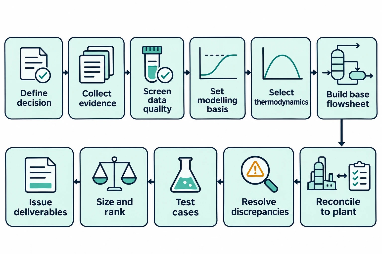
EnerTherm Engineering applies an 11-step heat and mass balance framework to move from fragmented site data to defined engineering decisions.
-
Define the decision. Set the scope, modification, success criteria, process boundary and required cases.
-
Collect plant evidence. Assemble P&IDs, PFDs, historian records, laboratory data, operating logs and equipment documents.
-
Screen data quality. Identify missing measurements, mismatched time periods, instrument concerns and uncertain composition data.
-
Establish the modelling basis. Record feed conditions, operating constraints, utilities, assumptions and exclusions.
-
Select thermodynamic methods. Match the property method to chemistry, phase behaviour and operating range.
-
Build the base flowsheet. Represent the relevant reactors, separators, columns, exchangers, compressors, recycle paths and utilities.
-
Reconcile against plant operation. Compare the model with measured flows, assays, temperature profiles, duties and pressure drops.
-
Resolve discrepancies. Investigate data gaps, fouling, bypasses, leaks, unmeasured flows and incorrect documentation.
-
Test modification and upset cases. Assess normal, maximum-rate, minimum-utility and credible abnormal scenarios.
-
Size and rank options. Produce equipment-duty summaries, identify constraints and compare yield, energy, CO₂ and operability effects.
-
Issue traceable deliverables. Provide a validated model, PFDs with stream tables, heat and mass balances, energy mapping, assumptions register and recommended site tests.
The completed package should separate measured values from calculated values. It should also specify the operating range for which the model has been validated.
Turning Modifications into Defensible Engineering Decisions
A throughput project may begin with a nominal 10% capacity target. The model may show that a reactor can support the additional feed but that the existing condenser reaches its calculated duty limit at 6% above baseline under the highest expected cooling-water temperature. The decision then becomes specific: retain the 6% limit, provide additional condensation capacity, reduce vapour generation or revise the project basis.
A recycle analysis can make the same point. If a proposed purge reduction cuts solvent losses by 0.5 t/h but pushes a trace impurity above the product or corrosion constraint after several residence times, the project team has a measurable trade-off. The result should include the predicted accumulation rate, new steady composition, purge requirement and uncertainty in the feed impurity measurement.
For heat recovery, the 2 MW illustrative case shows why annual hours and utility displacement matter. A project operating for 4,000 rather than 8,000 hours would recover 8,000 MWh, with the same assumptions producing roughly 1,620 tCO₂e per year of avoided emissions.
This article reflects the independent analysis and editorial opinion of EnerTherm Engineering. Product names, trademarks, and brands mentioned belong to their respective owners. EnerTherm Engineering is not affiliated with, endorsed by, or a licensee of any third-party software or product mentioned unless explicitly stated.

Senior Process Engineer — EnerTherm Engineering
Masab Javed is a Senior Process Engineer at EnerTherm Engineering with extensive expertise in chemical process design, decarbonisation, and sustainable industrial solutions. He holds an MSc from TUM School of Management and a BEng in Chemical Engineering from NUST, with experience spanning ammonia production, CO2 capture, and semiconductor manufacturing optimisation.
