Steady-State Process Modelling in Chemical Processing
An 11-step framework validates Aspen HYSYS and DWSIM balances for debottlenecking.
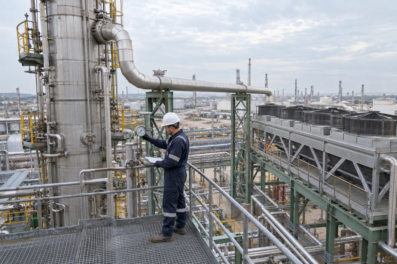
A steady-state process model is a mathematical representation of a chemical plant at a defined operating condition, in which stream flow, composition, temperature, pressure and energy duties remain constant over time. A distillation train can appear to have spare capacity until a recycle composition changes, condenser duty rises and the column approaches its hydraulic limit. A validated flowsheet exposes that chain before a plant commits capital.
Steady-state process modelling turns P&IDs, laboratory assays, historian records, operating logs and equipment information into a reconciled heat and mass balance. For senior process engineers, its value is traceability. The model should explain the current operating point, quantify plant constraints and show how proposed changes affect the connected process.
This matters where equipment interactions are tightly coupled. A fouled exchanger changes feed temperature. That shifts flash conditions and vapour load to a compressor or column. An apparently local modification can move the bottleneck downstream.
For petrochemical and speciality chemical projects, steady-state process modelling provides the engineering baseline for capacity studies, utility reviews, yield investigations and major CAPEX decisions.
What steady-state process modelling calculates
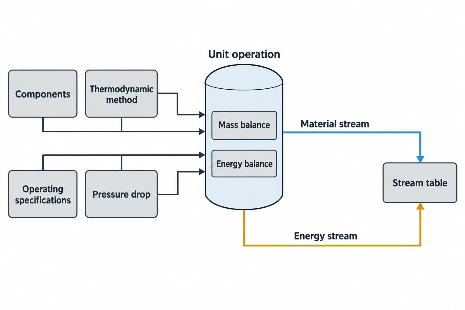
A steady-state flowsheet applies overall mass balances, component balances and energy balances to each unit operation and the defined process boundary. Thermodynamic calculations provide phase fractions, enthalpy, density, heat capacity and equilibrium compositions. Together, they define every material and energy stream.
A useful model contains more than connected icons. It should include a clear component list, a documented thermodynamic method, operating specifications, pressure drops and a complete stream table.
The operating case must match the decision
Steady state describes a selected process condition. It does not claim that the plant remains unchanged throughout a production campaign. The modeller must choose a representative time window and explain why it is appropriate.
Typical cases include:
- Normal production at a stable rate
- Maximum observed throughput before a debottlenecking project
- A future feedstock with different water, impurity or heavy-end content
- Seasonal utility constraints, such as high cooling-water temperature
- A known constrained case, such as low reflux capacity or a high non-condensable gas load
Monthly averages can hide the conditions that determine a capacity limit. A column may meet its product specification at average feed density but lose separation margin during shorter periods of heavier feed. The selected operating window must answer the project question.
What the finished model should deliver
A decision-grade steady-state model normally produces a process flow diagram with embedded stream tables, reconciled heat and mass balances, an equipment-duty summary and a property-method record. It should identify:
- The active constraint at the present operating rate.
- The impact of feed, composition, pressure and utility variation.
- The expected effect of each modification on downstream equipment.
- The operating margin remaining after the modification.
- The uncertain measurements or assumptions that could change the conclusion.
EnerTherm Engineering’s 11-step heat and mass balance methodology begins with project scoping and data acquisition, then develops the validated model into a single source of technical truth for the chosen case.

Map every energy and material flow in your process with detailed heat and mass balance calculations — the foundation for any optimisation or design project.
Building a plant-representative heat and mass balance
A solver can converge a flowsheet built from poor data. The result may be internally consistent while bearing little resemblance to the plant. Data quality, source control and reconciliation determine whether the model can support an investment decision.
Start with operating evidence
Original design information remains valuable for exchanger area, tray count, vessel dimensions, design pressure, installed pump curves and line sizes. It should not automatically define current performance. Fouling, catalyst ageing, changed feedstock, altered control practices and equipment modifications can move the plant far from its original design basis.
A practical data pack may include:
- Current P&IDs and process flow diagrams
- Equipment datasheets and vendor curves
- Historian data for flow, pressure, temperature and composition
- Laboratory assays and sample records
- Utility flow and supply-condition data
- Maintenance history and inspection findings
- Operating instructions, shift logs and previous process studies
The modeller should record the time period, source and confidence level for each input. Instrument maintenance periods, shutdowns, grade transitions, analyser faults and non-representative operating modes should be excluded before generating the base case.
A median from a stable operating period can be more representative than a single historian point. It also makes outlying measurements easier to identify and investigate.
Set clear battery limits
The model boundary may cover a reactor section, solvent-recovery train, distillation area or an entire production line. Every material stream crossing that boundary needs a defined flow, composition, temperature and pressure where relevant. Utility streams, vents, flares, purges, waste flows and make-up chemicals need the same attention.
Unmeasured flows often carry the greatest uncertainty. Common examples include water added by washing or steam injection, reflux inferred from pump performance, liquid carryover from a separator, vapour losses and heavy material excluded from a laboratory assay.
Reconciliation should preserve the original measurement and document any adjustment. A project team must be able to see which streams were measured, calculated or introduced as assumptions to close the balance.
Treat composition as a design variable
A total mass flow does not fully define a chemical process stream. The component list should include compounds that influence equilibrium, reaction heat, corrosion risk, product quality, emissions or separation duty.
A simplified component slate may be acceptable for an early screening model. A capacity case may need pseudo-components, trace water, dissolved gases, inerts, side products and heavy ends. The appropriate detail depends on process sensitivity.
Small quantities can matter. Water can alter liquid-liquid equilibrium in a solvent system. Carbon dioxide, hydrogen sulphide and light hydrocarbons can change dew-point prediction in a gas-processing system. A missing by-product can overstate reaction yield and understate distillation duty.
Thermodynamic validation in steady-state process modelling
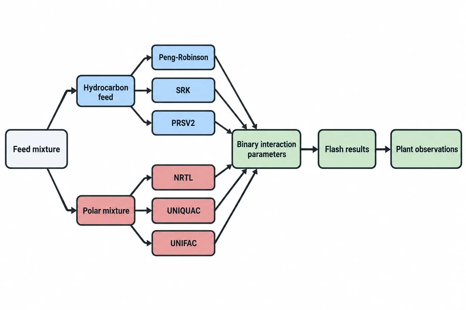
Thermodynamic package selection is one of the most important decisions in a flowsheet. The chosen method determines vapour-liquid equilibrium, liquid-liquid equilibrium, enthalpy, density, heat capacity and phase fraction. These properties drive separator performance, compressor duty, condenser load, reboiler duty and product recovery.
A method that gives credible flash results for a hydrocarbon feed may be unsuitable for a water-rich absorber or azeotropic separation.
Equations of state for hydrocarbon systems
Peng-Robinson and Soave-Redlich-Kwong are established cubic equations of state used in hydrocarbon processing, gas separation and refining. Peng-Robinson-Stryjek-Vera 2, commonly known as PRSV2, is another option where available parameters and validation evidence support its use.
Binary interaction parameters deserve close scrutiny. Missing, unsuitable or poorly sourced parameters can materially affect predicted dew points, liquid dropout and phase composition. The issue becomes more significant where carbon dioxide, hydrogen sulphide, water or polar compounds occur in the mixture.
Validation should compare model predictions with plant observations, including separator vapour fraction, saturation temperature at measured pressure, stream density, compressor suction condition, product recovery and measured heat duties.
Activity coefficient models for non-ideal liquid mixtures
NRTL and UNIQUAC are established activity coefficient models for strongly non-ideal liquid systems. They are frequently applied to mixtures containing polar organics, water, alcohols, acids and solvents, where molecular interactions influence separation performance.
UNIFAC methods can support early-stage studies where measured interaction parameters are unavailable. Group-contribution predictions should prompt further testing before supporting a major equipment decision, particularly where the project depends on an azeotrope, liquid-liquid split or tight product specification.
Relevant experimental evidence may include bubble points, dew points, azeotropic compositions, liquid-liquid equilibrium data and calorimetric measurements. Plant data often provides the most useful check because it includes real feed impurities and operating conditions.
Aspen HYSYS and DWSIM model comparison
Process simulation teams often use Aspen HYSYS and DWSIM for steady-state flowsheet work. DWSIM is open source and supports CAPE-OPEN interfaces, including interoperability with suitable property packages and unit operations. Its available property packages include Peng-Robinson, PRSV2, SRK, NRTL, UNIQUAC and UNIFAC variants.
Cross-platform comparison requires a controlled basis. Engineers should align:
- Component identities and pseudo-component characterisation
- Thermodynamic method and binary interaction parameters
- Stream reference conditions and enthalpy basis
- Unit-operation specifications and pressure drops
- Column efficiency assumptions and convergence tolerances
- Heat-loss assumptions and phase-handling settings
Different results do not automatically indicate a software defect. They can arise from differing compound databases, interaction-parameter coverage, default correlations or specification handling. The meaningful test is whether the documented model can reproduce trusted plant observations.

Map every energy and material flow in your process with detailed heat and mass balance calculations — the foundation for any optimisation or design project.
Recycle-loop modelling and flowsheet convergence
Recycle loops can provide some of the strongest insights in steady-state flowsheets. They also create difficult convergence problems.
A recycle may return unreacted feed, recovered solvent, hydrogen, wash water, catalyst slurry, purge gas or off-spec material upstream. Its flow and composition depend on downstream separation, which then depends on the recycle. The flowsheet must resolve both directions at once.
Establish physical logic before solver settings
A simulator closes a recycle by iterating until the estimated recycle stream matches the calculated stream returning from the loop. High recycle ratios, sharp phase changes, interacting specifications and sensitive components can slow or prevent convergence.
Solver settings can improve numerical behaviour, but cannot correct an incomplete process definition. The process engineer should first identify:
- The recycle boundary and tear-stream location
- The purge point and its operating rule
- The pressure-driving pump, compressor or control arrangement
- Separator phase split and carryover assumptions
- Pressure drops through equipment and piping
- Controlled variables used in the plant
- Practical operating limits for temperature, pressure and composition
A recycle loop that converges only after unrealistic specifications are imposed has identified a modelling issue, not a reliable operating case.
Use an open-loop build sequence
A disciplined workflow starts with the recycle open. The modeller specifies a defensible estimated recycle stream, solves the downstream equipment, validates the major operations and closes the loop only after intermediate results are credible.
The final review should confirm whole-system material closure before equipment-level conclusions are drawn. It should also test the purge treatment of inerts, heavy components and reaction by-products. These components can accumulate in a recycle even where their concentration in fresh feed is low.
A converged result needs plant comparison. Recycle flow, composition, temperature and pressure should be checked against measurements where they exist. This is particularly important where the recycle determines compressor loading, reactor feed ratio or column vapour traffic.
Debottlenecking with a validated steady-state flowsheet
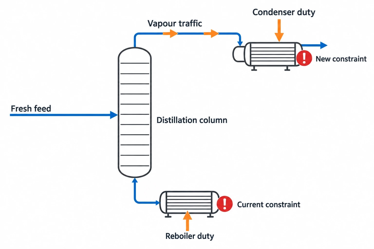
A capacity study must identify the active constraint at each throughput case. Potential constraints include reactor heat removal, pump head, compressor capacity, exchanger area, cooling-water temperature, steam availability, column flooding tendency, condenser duty and product specification.
The model should raise feed rate in controlled increments while retaining the operating rules used by the plant. If operators adjust reflux, pressure setpoint, quench flow or purge rate as throughput changes, those actions belong in the case definition.
Test the whole process, not a single item
A local improvement can transfer the constraint. Extra reboiler duty may increase vapour traffic and push a downstream condenser or column towards its limit. A larger feed pump may expose insufficient exchanger area. Increased recovery can raise impurity concentration in a recycle loop.
A clear case register helps project teams compare options on a consistent basis:
| Case | Change tested | Key checks |
|---|---|---|
| Base case | Current representative operation | Balance closure, product quality, utility duties |
| Throughput case | Higher fresh-feed rate | Equipment loads, recycle growth, utility margin |
| Feed-quality case | Changed assay or impurity level | Phase split, recovery, product specification |
| Utility case | Limiting steam or cooling condition | Heat duty, outlet temperatures, separation performance |
| Modification case | Proposed equipment or operating change | Constraint movement, remaining margin, downstream effects |
The model should report heat duty, flow rate, temperature, pressure, phase fraction and composition for each key stream. Equipment summaries should state whether the result represents current operation, an estimated performance limit or a design requirement for the proposed project.
Link energy and carbon decisions to the balance
Validated heat and mass balances provide a technical basis for comparing energy use before and after a modification. ISO 50001:2018 remains current and provides a framework for improving energy performance, including energy efficiency, energy use and energy consumption.
For UK installations covered by the UK Emissions Trading Scheme, emissions reporting follows an approved monitoring plan and the scheme’s monitoring, reporting and verification requirements. A process model can support engineering analysis of fuel use, material flows and potential CO₂ mitigation, but it should not replace the site’s approved monitoring and reporting methodology.
Acceptance checks for a decision-grade model
A project team should agree validation criteria before using a model to support CAPEX approval. Acceptance should rely on comparisons relevant to the decision, rather than a generic statement that the simulation has converged.
| Model area | Plant comparison | Risk if weak |
|---|---|---|
| Feed characterisation | Flow, assay, density, water and impurity content | Incorrect material balance and phase prediction |
| Thermodynamic method | VLE, LLE, vapour fraction, density and saturation condition | Misstated recovery, utility duty or separation result |
| Reactor representation | Conversion, selectivity, temperature and heat duty | Incorrect yield and heat-removal requirement |
| Heat exchange | Outlet temperatures, duty and pressure drop | Misstated utility demand or exchanger requirement |
| Recycle system | Recycle flow, composition, purge and pressure | False convergence or misplaced bottleneck |
| Distillation performance | Product quality, reflux, condenser and reboiler duty | Inaccurate capacity and operating-margin assessment |
A strong handover includes the flowsheet file, property-method selection record, source-data register, stream tables, equipment-duty summaries, model assumptions, validation comparisons and sensitivity cases. That documentation lets a future engineer update the model when feedstock, equipment condition or production targets change.
Steady-state process modelling represents defined operating conditions and their process-wide consequences. Transient equipment response and control-system performance require separate engineering studies. For debottlenecking, the immediate requirement is a defensible flowsheet that connects plant measurements to the proposed investment and shows where the next constraint will emerge.
This article reflects the independent analysis and editorial opinion of EnerTherm Engineering. Product names, trademarks, and brands mentioned belong to their respective owners. EnerTherm Engineering is not affiliated with, endorsed by, or a licensee of any third-party software or product mentioned unless explicitly stated.

Senior Process Engineer — EnerTherm Engineering
Masab Javed is a Senior Process Engineer at EnerTherm Engineering with extensive expertise in chemical process design, decarbonisation, and sustainable industrial solutions. He holds an MSc from TUM School of Management and a BEng in Chemical Engineering from NUST, with experience spanning ammonia production, CO2 capture, and semiconductor manufacturing optimisation.
