Why WFI Heat Recovery Can Cut Clean Utility Energy Waste
A GMP-aligned route to lower distillation steam and condenser cooling demand.
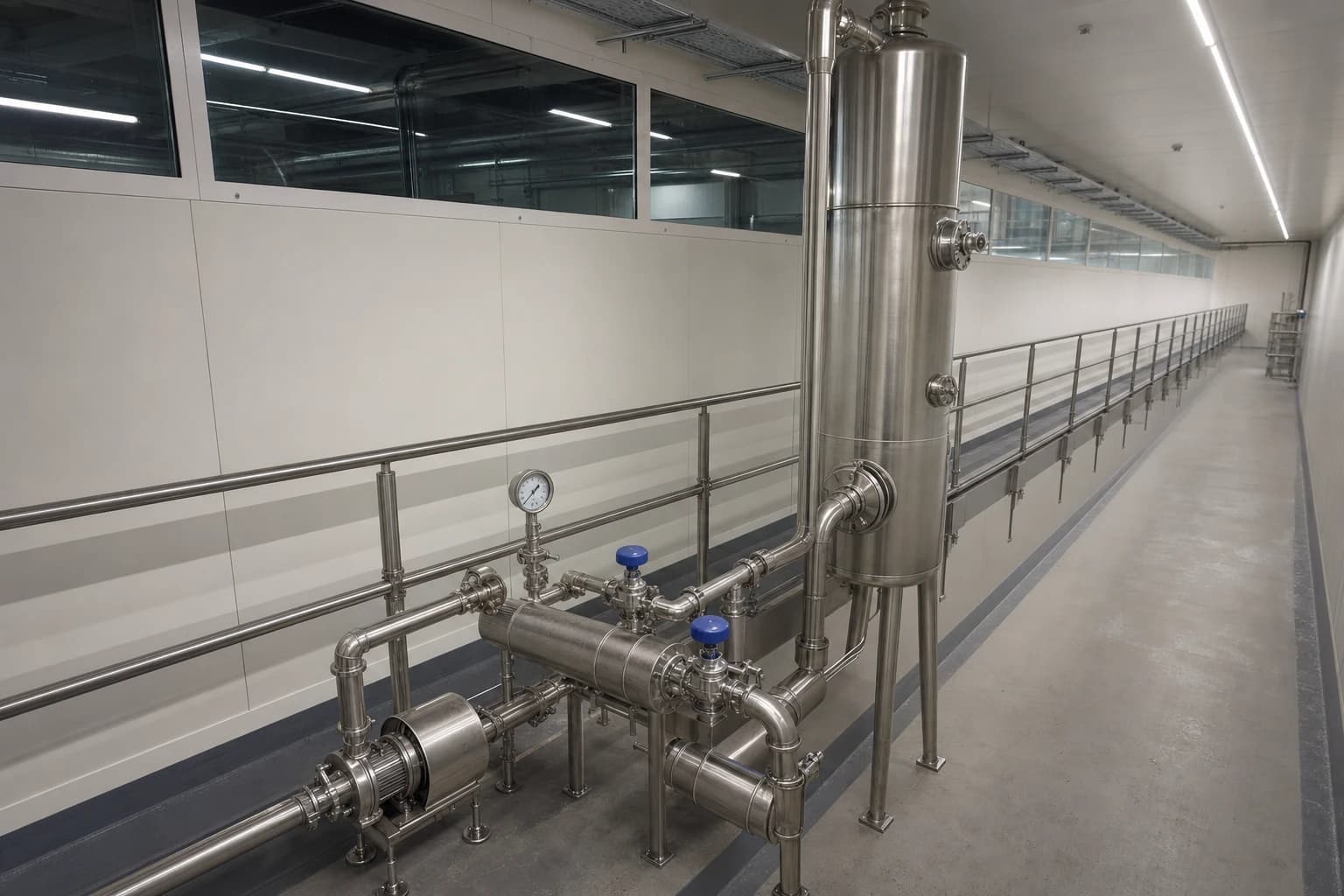
Water for Injection heat recovery captures and reuses heat from WFI generation, circulation, cooling or associated wastewater without compromising pharmaceutical water quality. In a conventional distillation-based WFI system, heating steam produces the water while condenser cooling water removes heat. The WFI loop is then held hot and often cooled again at the point of use. This sequence creates a sizeable clean utility energy-efficiency opportunity.
For facilities and utilities engineers, the task is more exacting than fitting a heat exchanger. WFI and pure steam are GMP-critical utilities. Any altered temperature profile, process-contact surface, instrument location or flow arrangement may affect the qualified state of the system. Energy recovery must therefore sit within a documented engineering and validation programme.
The strongest projects begin with a measured heat balance. They identify where heat leaves the WFI system, match it to a reliable low-temperature demand, and verify savings without weakening microbial control, monitoring or clean-steam quality.
Why WFI Systems Create Recoverable Energy Losses
Distillation uses heat twice
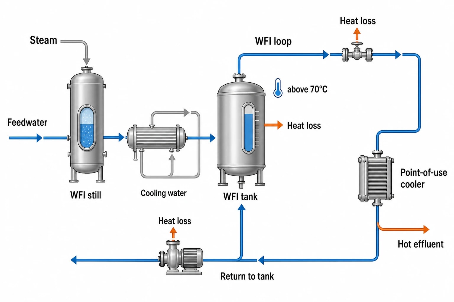
Distillation-based WFI production consumes a heat source, commonly plant steam, to evaporate purified feedwater. The system then rejects condensation heat through a condenser cooling-water circuit. Generated WFI is often retained in a hot storage and distribution system as a microbial-growth control measure.
This creates several thermal duties in close proximity:
- Steam or another heat source supplies the still.
- Cooling water carries heat away from the condenser.
- The WFI storage vessel and recirculation loop lose heat continuously to their surroundings.
- Point-of-use coolers remove energy from hot WFI shortly before use.
- Hot water and cleaning effluent may leave manufacturing areas without useful heat recovery.
The International Society for Pharmaceutical Engineering has highlighted that distillation-based WFI uses heating steam and substantial condenser cooling water. It also identifies wastewater heat recovery as a potential pharmaceutical decarbonisation measure where the system is designed and validated accordingly.
Hot circulation protects quality and consumes energy
EU GMP Annex 1 sets the operating context. Section 6.9 says water flow should remain turbulent through pipework to minimise microbial adhesion and subsequent biofilm formation. Section 6.10 gives continuous circulation above 70°C as an example of controlling microbial growth in WFI storage and distribution.
A hot loop continuously rejects heat through pipe insulation, valves, supports, pump casings and the tank shell. A poorly insulated valve cluster or continuously open low-use branch can add a recurring steam burden that remains invisible in a monthly gas bill.
The recovery opportunity often becomes clearer after mapping the utility route: feedwater to still, distillate to tank, tank to loop, loop to point of use, and return to tank. Losses may arise at the generator, a local cooler, or where hot effluent combines with colder drain streams and loses useful temperature.

Identify where your plant is losing energy and quantify the savings potential — our audits map every heat source, sink, and waste stream in your facility.
Where WFI Heat Recovery Fits Into Clean Utility Energy Efficiency
Recover condenser heat before it reaches the cooling system
A distiller condenser rejects a stable heat load while WFI production is running. That heat can pass through an indirect heat exchanger to a suitable non-product-contact load. Typical recipients include incoming water for a utility preheat duty, a lower-temperature heating circuit, or another process demand that coincides with WFI production.
The match must reflect real operating conditions. A batch facility may operate its WFI still intermittently while a recipient heating load peaks at a different time. Engineers should assess flow, temperature, operating hours, control response and seasonal demand before assigning a saving.
Recovery that displaces boiler steam and cooling-system electricity can affect more than one utility meter. The verification boundary should capture the utility services genuinely affected by the measure.
Recover heat from WFI loop cooling
Hot WFI is frequently cooled close to the point of use. The cooler transfers useful energy from a GMP-controlled utility into a cooling-water circuit, where it may then be rejected by chillers or cooling towers. An indirect recovery arrangement can redirect part of this duty to incoming water or another compatible sink.
This approach needs careful design because point-of-use demand is variable. A recovery circuit must not destabilise delivery temperature, leave stagnant sections, restrict the required recirculation regime or weaken loop control. Isolation valves, bypass operation, drainage, sanitary construction and maintenance access belong in the engineering assessment.
A dedicated intermediate circuit provides a defined thermal boundary between the WFI utility and the recipient system. The design team should assess heat-exchanger integrity, pressure relationships, leak detection, materials of construction and the consequence of failure through formal quality risk management.
Preserve temperature gradients in cleaning effluent
High-temperature wastewater has more recovery value before it mixes with cooler drains. A first-rinse or cleaning discharge can be a practical donor stream where it is segregated, characterised and available at a useful temperature.
Energy recovery from wastewater transfers heat only. It does not make wastewater suitable for reuse in a clean utility or product-contact application. Where a site considers recirculated washing or a change in cleaning duration, the change needs a separate assessment of cleaning effectiveness. ISPE notes that reducing unnecessary cleaning time requires reconfirmation through cleaning validation.
| Recovery source | Potential heat recipient | Engineering focus |
|---|---|---|
| Distiller condenser duty | Utility feedwater or low-temperature heating circuit | Coincident demand, heat-exchanger approach temperature, cooling-water reduction |
| WFI point-of-use cooler | Incoming utility water or compatible process preheat | Delivery temperature control, loop hydraulics, sanitary segregation |
| Segregated hot cleaning effluent | Non-product-contact preheat duty | Drain segregation, fouling, cleanability and operating availability |
| Hot WFI return or tank overflow where applicable | Indirect utility preheat | Continuous circulation, microbial-control strategy and qualification impact |
WFI Production Choice Changes the Energy Baseline
Distillation remains a major audit target
Multiple-effect distillation and vapour-compression technologies have established operating histories. Their thermal requirements make them important targets for an industrial energy audit, particularly where WFI demand is high and steam generation has a material carbon and cost burden.
An audit should separate generation energy from distribution energy. An efficient still can still feed a poorly controlled hot loop. Equally, extensive recovery around a still cannot offset unnecessary WFI consumption in cleaning, flushing or production scheduling.
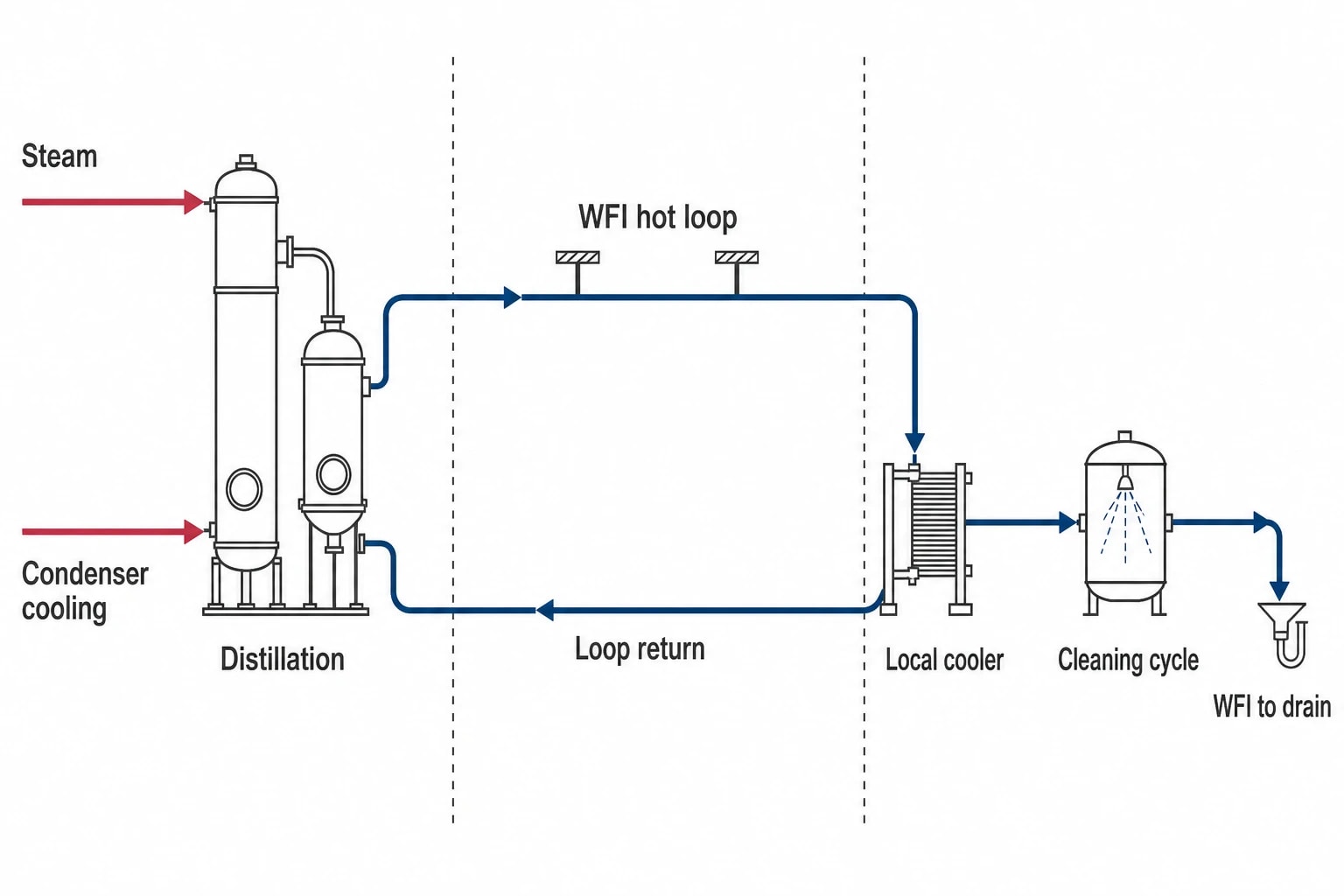
Useful indicators include WFI produced per batch, steam supplied per unit of WFI, condenser cooling-water use, WFI sent to drain, loop return temperature, local cooler duty and WFI used per cleaning cycle. These measures reveal whether the main loss sits in generation, distribution or consumption.
Membrane-based WFI can alter the heat-recovery case
The EMA Guideline on the Quality of Water for Pharmaceutical Use reflects the revised European Pharmacopoeia position that WFI may be produced by distillation or by a purification process demonstrated to be equivalent to distillation. The guideline identifies approaches including double-pass reverse osmosis coupled with additional treatment such as electrodeionisation, ultrafiltration or nanofiltration.
This does not make a membrane-based system an automatic retrofit answer. Raw-water quality, pretreatment, microbial-control strategy, sanitisation approach, lifecycle cost, available electrical capacity and validation requirements all affect the decision. A cold or ambient-temperature generation route can remove much of the recoverable distillation heat while reducing the steam and cooling duties that created it.
Facilities therefore need to evaluate two distinct questions:
- Can existing distillation heat be recovered safely and economically?
- Does the site’s future WFI demand justify reassessing its generation technology and distribution strategy?
Both questions belong in a clean utility energy-efficiency plan. They have different capital, quality and operational implications.

Identify where your plant is losing energy and quantify the savings potential — our audits map every heat source, sink, and waste stream in your facility.
GMP and Validation Define the Project Boundary
Annex 1 requirements remain fixed
Energy projects must retain the controls that protect WFI and pure steam quality. Annex 1 requires continuous monitoring of total organic carbon and conductivity in WFI systems. Sensor locations should follow risk-assessment and qualification outcomes.
A recovery project can affect those outcomes if it changes hydraulic conditions, temperature, tank behaviour, sampling arrangements or the response to an upset. The utility team should establish quality-critical parameters before design freeze, including distribution temperature, return temperature, circulation performance, conductivity, TOC, microbiological monitoring and endotoxin controls.
Annex 1 also requires appropriately purified feedwater for a pure-steam generator. The generator must be designed, qualified and operated to achieve defined chemical and endotoxin quality. Heat recovery on shared utility systems must not introduce a route that affects feedwater quality or the quality of pure steam used for direct sterilisation.
Treat the modification as a controlled GMP change
EU GMP Annex 15 requires planned changes to facilities, equipment, utilities and processes that may affect product quality to be formally documented. The manufacturer must assess the effect on qualified or validated status and on the control strategy.
For a WFI heat-recovery project, the change-control package commonly needs to cover:
- A quality risk assessment defining all new utility interfaces.
- Updated process and instrumentation diagrams, piping drawings and operating descriptions.
- Material and hygienic-design assessments for added pipework and heat exchangers.
- Functional specification and alarm assessment for controls, bypasses and failure modes.
- Installation qualification evidence for equipment, instruments and calibration.
- Operational qualification of normal operation, start-up, shutdown, bypass and fault response.
- Performance qualification evidence that the WFI and pure-steam systems continue to meet approved requirements under representative demand.
- An updated preventive-maintenance, inspection and sampling programme.
Validation leads should be involved before procurement. A technically attractive recovery scheme can become expensive if its quality impact emerges only after construction.
How an Energy Audit Should Measure WFI Heat Recovery
Meter the thermal system, not only the boiler house
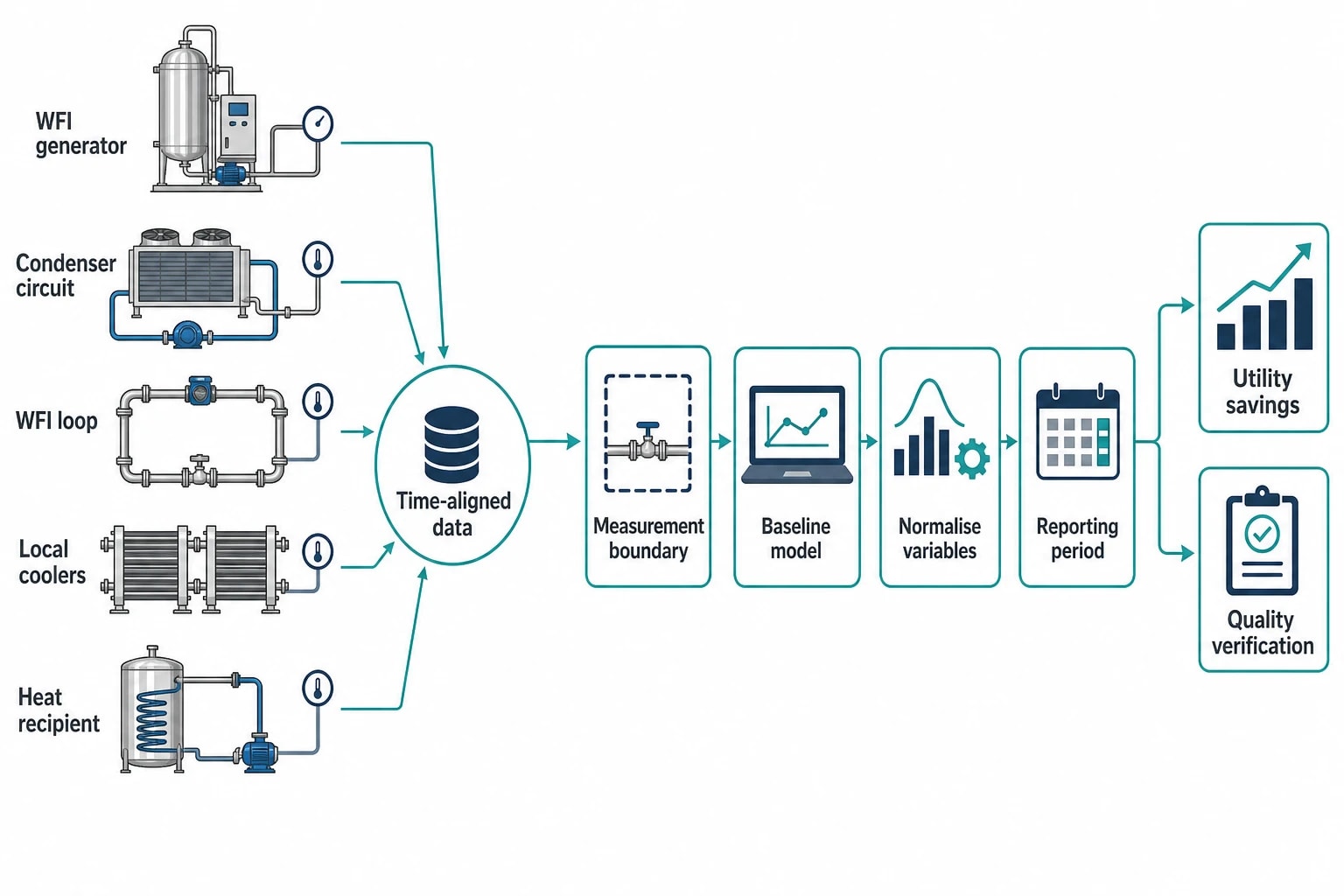
Monthly steam consumption cannot isolate WFI savings when production volumes, cleaning demand and seasonal cooling loads change. The audit needs time-aligned data from the WFI generator, condenser circuit, loop, local coolers and intended heat recipient.
Relevant measurements include steam flow to the still, feedwater flow, WFI production volume, condenser cooling-water flow and temperatures, WFI supply and return temperatures, recovered-heat circuit temperatures, and electrical consumption of affected pumps or cooling equipment. Production records should identify batches, clean-in-place cycles, shutdowns and atypical operating periods.
Thermal imaging can expose insulation losses, hot valves and bypass leakage. Ultrasonic leak detection can support a broader steam-system assessment. Power analysers help establish the electrical effect of pumps, cooling towers and chillers. These tools support site data rather than replacing calibrated utility metering.
Build a production-normalised baseline
A useful baseline distinguishes energy consumed because WFI was produced from energy consumed because the system remained hot between demands. It also records variables that change energy use: WFI volume, operating hours, feedwater temperature, cleaning schedule, ambient conditions and product campaign pattern.
EnerTherm Engineering’s seven-step audit methodology provides a practical route: initial consultation, on-site assessment, energy-model analysis, identification of conservation measures, report preparation, implementation support and ongoing monitoring. For WFI, the site assessment should include a GMP utility walkdown with facilities, engineering, production and quality representatives.
This joint review prevents an energy model from treating a quality-control duty as avoidable waste. The team can then identify which losses are necessary to maintain the qualified state and which arise from avoidable cooling, excess use, poor insulation or mismatched utility temperatures.
Verify savings alongside quality performance
An IPMVP-aligned measurement and verification plan should define the baseline period, reporting period, measurement boundary, normalisation variables and treatment of non-routine events. The plan should be agreed before implementation while the original operating condition remains measurable.
Quality monitoring must run alongside energy verification. A reduction in steam consumption is not successful if it coincides with loss of WFI temperature control, increased alert-level events, changed conductivity trends or an unqualified operating state.
Project reporting should present both sets of evidence: measured utility savings and documented proof that WFI, purified-water and clean-steam performance remain within approved limits.
A Practical Sequence for WFI Heat-Recovery Projects
Start with demand reduction
Heat recovery should follow a review of WFI demand. Each unnecessary litre avoided removes the energy needed to generate, circulate, cool and dispose of it. Cleaning-cycle duration, rinse volume, flushing practice, leakage, point-of-use behaviour and production scheduling can all change WFI demand.
Any alteration to a validated cleaning process needs formal assessment. The energy objective should be clear, but cleaning acceptance criteria and patient-protection requirements remain the governing conditions.
Match one donor to one dependable sink
Start with the most stable donor stream and the most consistent recipient load. A narrowly defined first project is easier to measure, qualify and maintain than an arrangement connecting several variable systems. The design should retain safe bypass operation so WFI quality and supply reliability do not depend on continuous recovery availability.
Commissioning should prove the thermal and GMP control response during representative conditions, including low demand, high demand, start-up, maintenance bypass and recovery-circuit failure.
Use the results to guide the next investment
Once measured data show where energy is lost, a site can sequence further measures: insulation remediation, local-cooler optimisation, wastewater segregation, distiller heat recovery, WFI-use reduction or a longer-term change in generation technology.
This article reflects the independent analysis and editorial opinion of EnerTherm Engineering. Product names, trademarks, and brands mentioned belong to their respective owners. EnerTherm Engineering is not affiliated with, endorsed by, or a licensee of any third-party software or product mentioned unless explicitly stated.

Technical Manager — EnerTherm Engineering
John Naranjo is Technical Manager at EnerTherm Engineering, bringing specialist expertise in chemical and environmental engineering. He recently led the implementation of Omni Vision, EnerTherm's real-time energy and utility monitoring platform. He holds an MSc in Environmental Engineering from the University of Huelva and a BSc in Chemical Engineering, with memberships in both the Energy Institute and IChemE.
