How Pharmaceutical Cold Chains Cut Energy Under GMP
A technical explanation of temperature mapping, validated controls and F-gas compliance
Pharmaceutical cold chain energy efficiency is the reduction of refrigeration electricity use and refrigerant losses while qualified storage conditions, product quality and GMP evidence remain within approved limits.
Carbon Trust guidance for cold stores indicates that maintaining thermal integrity and airtightness can save more than 10% of energy costs. In a pharmaceutical facility, however, that work cannot be treated as a facilities-only improvement. A door-seal replacement, revised defrost schedule or condenser control change can affect temperature distribution, recovery after disturbance and the validated state of the storage area.
That is the central discipline. Cold rooms, refrigerated warehouses, stability chambers, freezers and temperature-controlled dispatch areas should reduce load first, then optimise plant operation inside a documented quality framework.
Why pharmaceutical cold chain energy efficiency is a GMP change
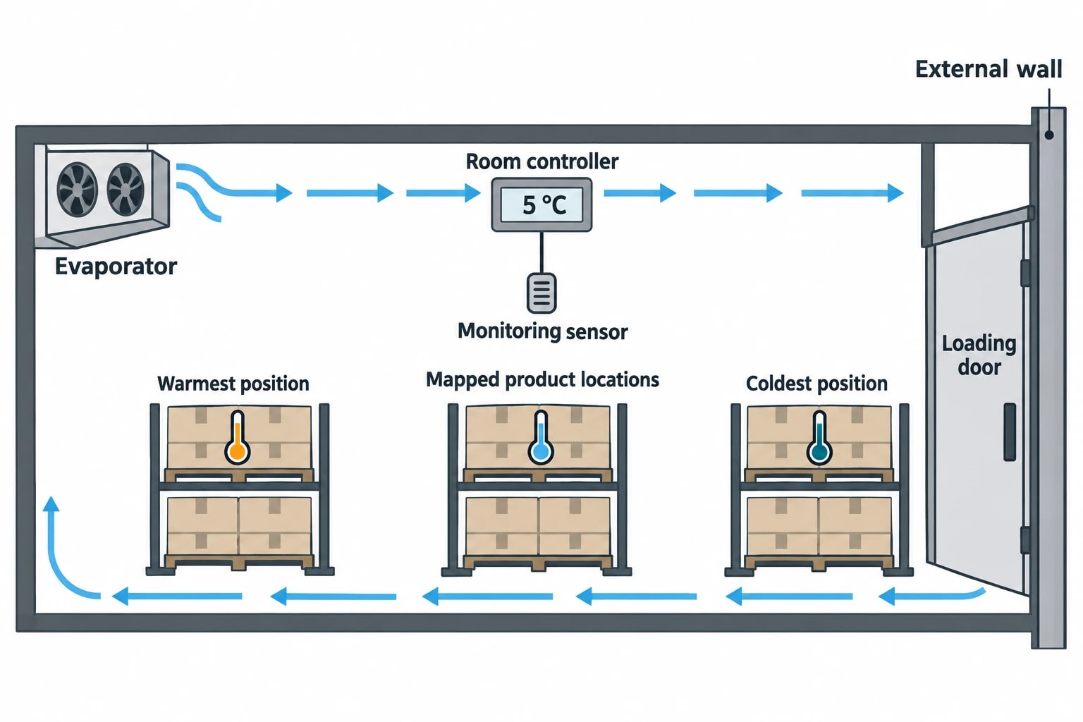
Refrigeration protects the approved storage condition before it delivers an energy target. A room controller may show 5 °C while product positions close to a loading door, external wall or evaporator experience different conditions. The controller display is therefore only one part of the evidence.
The EU GDP Guidelines 2013/C 343/01 require temperature mapping before storage areas enter service, under representative conditions. They also require monitoring equipment to be positioned according to mapping results, particularly where the greatest temperature variation occurs. Equipment should be calibrated to traceable standards, alarm systems should be tested, and maintenance and calibration records should be retained.
A refrigeration efficiency measure becomes a GMP-controlled change where it could alter:
- Temperature distribution across mapped product locations.
- Recovery time after door openings, defrost or loss of power.
- Alarm limits, delays, escalation or response procedures.
- Humidity conditions in a stability chamber.
- Calibration, maintenance or preventive-maintenance requirements.
- The relationship between the control sensor and the warmest or coldest product position.
EU GMP Annex 15 requires planned changes to facilities, equipment, utilities and processes that could affect product quality to be documented. The manufacturer must assess the effect on validated status and the control strategy. Quality Assurance, engineering and cold-chain operations should therefore approve the technical scope, risk assessment and acceptance criteria before changing a setpoint, control sequence or refrigeration component.

Identify where your plant is losing energy and quantify the savings potential — our audits map every heat source, sink, and waste stream in your facility.
Build one baseline from temperature and energy data
Temperature mapping and electricity metering answer separate questions. Mapping establishes whether the storage environment remains suitable for the product. Metering identifies the electrical consequence of refrigeration operation. An energy audit should align both datasets on the same time basis.
Use mapped locations as quality acceptance points
Mapping should represent the operating condition that presents the greatest credible risk. That may include full racking, low stock, frequent loading activity, high ambient temperatures, defrost operation and normal evaporator airflow.
Sensor placement should cover locations such as:
- High-level positions where warmer air can collect.
- Racking near evaporators, where cold spots may occur.
- Product positions furthest from cooling equipment.
- Loading-door and dispatch interfaces.
- External walls and locations exposed to solar gain.
- Dense storage arrangements that restrict airflow.
The control sensor may be appropriate for operating the refrigeration plant. It does not automatically represent the warmest product location. The mapping report should identify the approved monitoring points and define which location governs the worst-case acceptance decision.
Meter the plant at component level
A whole-building electricity meter cannot distinguish a high condenser load from unnecessary fan operation or electric defrost. Install temporary or permanent interval metering around the refrigeration boundary, separating compressors, condensers, evaporator fans, defrost heaters and associated pumps where installed.
A practical baseline dataset includes:
| Dataset | Purpose in the analysis |
|---|---|
| Compressor and auxiliary kWh | Identifies the plant energy affected by the measure |
| Mapped temperature points | Confirms storage performance during the same intervals |
| Outdoor temperature and humidity | Allows comparison between differing weather conditions |
| Door-open minutes | Quantifies infiltration exposure |
| Pallet movements or throughput | Represents operational refrigeration load |
| Store occupancy or pallet-days | Normalises changing stock volume |
| Defrost start, duration and termination | Identifies avoidable heater operation and coil performance |
| Refrigerant additions and leak events | Links direct emissions risk with plant condition |
Use the pre-change data to establish a regression baseline for refrigeration electricity. Daily or shift-level refrigeration kWh should be modelled against outdoor conditions, door-open minutes, throughput and occupancy where those variables materially affect demand. The resulting model predicts the electricity expected under post-change operating conditions. Verified saving is the difference between that weather and activity-adjusted prediction and the metered post-change use.
This method is stronger than comparing one month with another. A mild month, lower throughput or fewer dispatch movements can otherwise appear as an engineering saving.
Set acceptance thresholds before implementation
The change-control protocol should state the thresholds before a contractor modifies the system.
For GMP performance, the acceptance criteria should include:
- Every mapped location remains within the approved storage range throughout the challenge test.
- Alarm tests pass at the approved setpoints and delays.
- Worst-case recovery remains inside the established qualified recovery limit.
- Calibration status, maintenance records and revised operating procedures are complete.
- Any humidity requirement for a stability chamber remains within its approved operating range.
The energy criterion should state the required reporting period, data-completeness requirement and operating conditions to be represented. A sensible protocol can require at least 95% usable interval data, include routine door traffic and defrost activity, and cover the expected range of ambient conditions before the site declares normalised savings. The target saving itself should be specific to the measure and asset, rather than borrowed from another cold store.
Reduce refrigeration load before adjusting controls
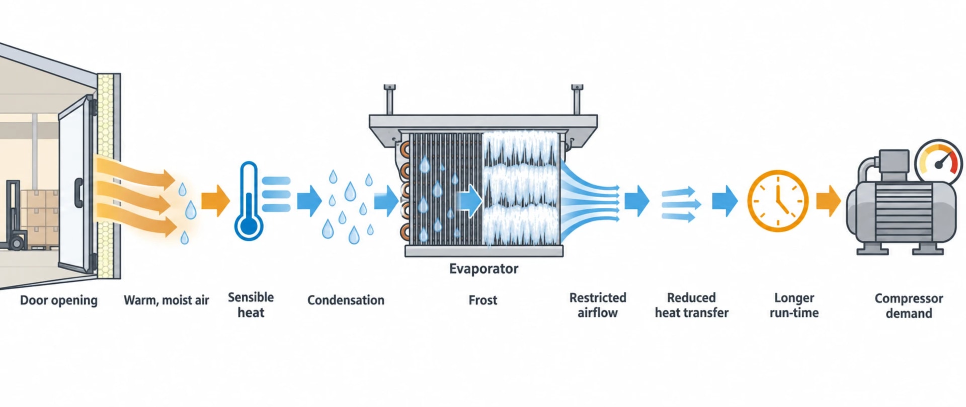
The least disruptive efficiency measures often prevent heat and moisture from entering the cold space. They reduce compressor demand without changing an approved storage temperature.
Control infiltration at cold-room doors
Each door opening introduces warmer, wetter air. The refrigeration system must remove sensible heat and condense or freeze that moisture. Frost then reduces evaporator heat transfer and can increase defrost demand.
Inspect door seals, automatic closing, strip curtains, dock seals, air curtains and panel joints. Review work practices too. A loading door held open during picking or stock checks can create a larger refrigeration load than a minor setpoint adjustment.
Carbon Trust guidance states that improved thermal integrity and airtightness can save more than 10% of cold-store energy cost. The figure is a cold-storage benchmark, not a pharmaceutical-site guarantee. Pharmaceutical facilities should validate the actual result through metered data and confirm that any new curtain, door arrangement or airflow device does not create a contamination, cleanability or temperature-distribution issue.
Maintain heat exchangers as energy assets
Dirty condenser fins, restricted water flow, failed fans and poor airflow raise condensing temperature and compressor power. Frosted evaporators restrict air movement and reduce cooling capacity. Both faults can lengthen plant run-time while increasing the risk of poor temperature recovery.
Maintenance checks should cover:
- Condenser and evaporator cleanliness.
- Fan condition and rotation.
- Drainage and condensate management.
- Defrost termination and frequency.
- Pipework insulation condition.
- Refrigerant charge indicators and recorded additions.
- Electrical connections and motor condition.
Thermal imaging can identify insulation defects, abnormal electrical heating and uneven coil temperatures. It should support calibrated temperature measurement and refrigeration engineering inspection, rather than replace either.
Quantify fan and defrost electricity
Auxiliary loads deserve direct measurement. A continuously operating 1 kW evaporator fan consumes 8.76 MWh a year. A 6 kW electric defrost heater running for 30 minutes, four times a day, consumes 4.38 MWh a year before considering any additional refrigeration required to remove that heat.
Those figures are examples, not benchmarks. Metering establishes whether fan and defrost loads justify action on a specific asset.
Variable-speed fan control can reduce fan power where airflow remains adequate across all mapped locations. Demand-based defrost can remove unnecessary heater operation where coil condition and room recovery remain acceptable. Each control sequence requires operational qualification because reduced fan speed can alter air distribution, while longer defrost intervals can allow frost accumulation.

Identify where your plant is losing energy and quantify the savings potential — our audits map every heat source, sink, and waste stream in your facility.
Optimise setpoints and deadbands with product evidence
Lower room temperatures increase the temperature lift across the refrigeration cycle and usually increase electricity use. A facility may have scope to remove inherited overcooling or an unnecessarily narrow deadband, but product evidence defines the boundary.
Approved range sets the limit
The approved storage condition, marketing authorisation commitments, stability information and site quality risk assessment govern the permissible operating envelope. The controller’s adjustment range does not create authority to change that envelope.
EMA GMP and GDP guidance confirms that products without a labelled storage statement still require temperature monitoring during storage and transport. The guidance refers to long-term stability data at 25 °C/60% RH or 30 °C/65% RH, with accelerated testing at 40 °C/75% RH, when justifying the absence of a storage statement for Europe.
That principle matters in a refrigeration project. A broad label statement does not remove the need for controlled, monitored storage conditions relevant to the product’s stability evidence.
Test controls through qualification
A change to a setpoint, deadband, floating head-pressure control or compressor sequence should proceed through a documented protocol. The protocol should assess room response under credible disturbances, including door openings, loading activity, defrost and power restoration where relevant.
Operational qualification should demonstrate that modified equipment performs as intended across anticipated operating ranges. Performance qualification should then demonstrate reproducible performance under representative operating conditions using production materials, qualified substitutes or simulated loads with equivalent thermal behaviour.
The test should compare the proposed control sequence against the existing qualified envelope. It should confirm that the warmest mapped location, coldest mapped location, alarm response and recovery behaviour all remain acceptable.
Refrigerant management supports energy and carbon performance
Refrigerant leakage causes direct greenhouse-gas emissions and can reduce cooling performance as charge falls. Leak detection and rapid repair therefore belong in energy management as well as environmental compliance.
EU and Great Britain F-gas requirements
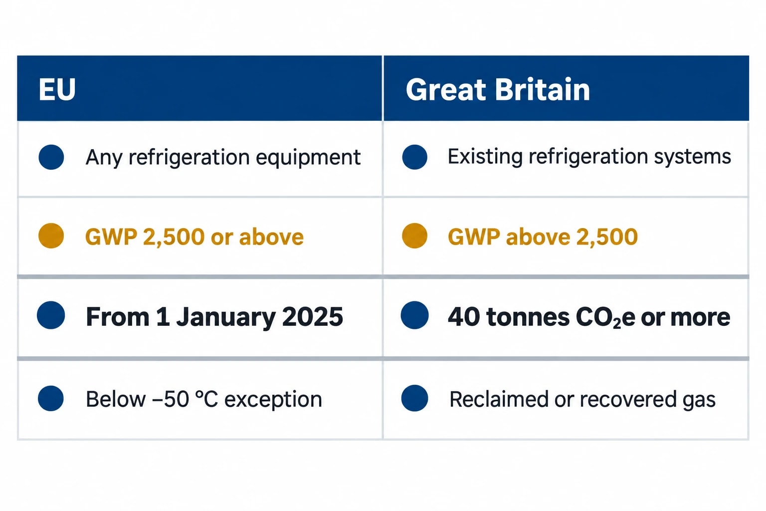
Regulation (EU) 2024/573 prohibits the use of fluorinated greenhouse gases with a global warming potential of 2,500 or above for maintenance or servicing of refrigeration equipment from 1 January 2025, subject to defined exemptions and transitional arrangements. Existing equipment designed to cool products below minus 50 °C is among the stated exceptions.
Great Britain applies separate F-gas rules. UK government guidance states that virgin F-gas with a global warming potential above 2,500 cannot be used to refill existing refrigeration systems containing 40 tonnes CO₂e or more, subject to specific exemptions. Reclaimed gas and gas recovered and recycled from similar equipment may remain available within the stated transition period.
Asset registers should record refrigerant type, charge, CO₂e quantity, leak checks, refrigerant additions and repair history. This information supports service planning and identifies assets where a leak, refrigerant restriction or declining efficiency makes retrofit or replacement necessary.
Investigate repeated refrigerant additions
A refrigerant top-up should trigger a plant-performance review. Engineers should investigate vibration, joints, valves, corrosion, oil return, pressure conditions and previous repair quality. Trend refrigerant additions alongside compressor kWh, discharge pressure and room recovery time.
UK F-gas guidance sets leak-check intervals by the system’s CO₂e charge. Automatic leak-detection systems affect those intervals at higher thresholds. The records should show that the operator found, repaired and verified leaks in line with applicable requirements.
A refrigerant replacement or system retrofit also requires GMP assessment. Capacity, refrigerant safety classification, component compatibility, defrost behaviour, alarm operation and temperature distribution can all change after the work.
Verify energy savings without weakening GMP evidence
IPMVP Core Concepts 2022 provides a useful structure for measurement and verification. For a cold-chain measure with dedicated meters, Option B, retrofit isolation with all-parameter measurement, can establish the energy change at equipment or system level. The measurement boundary should include the electricity directly affected by the measure.
The reporting plan should document:
- The meter locations and calibration arrangements.
- The baseline period and the operating conditions it represents.
- The variables used to normalise electricity consumption.
- The post-change reporting period.
- The treatment of planned or unplanned operational changes.
- The quality acceptance criteria and requalification evidence.
- The owner responsible for reviewing alarms, temperatures and savings.
Energy measurement and GMP qualification serve different decisions. Interval kWh data establishes whether the refrigeration measure reduced electricity consumption. Mapping, alarms, calibration records and qualification establish whether the storage environment remains fit for pharmaceutical use.
The strongest cold-chain projects retain both evidence streams. They lower electricity demand by reducing heat ingress, maintaining refrigeration hardware and tuning controls within the qualified operating envelope. That approach turns pharmaceutical cold chain energy efficiency into a documented engineering improvement rather than an uncontrolled utility intervention.
This article reflects the independent analysis and editorial opinion of EnerTherm Engineering. Product names, trademarks, and brands mentioned belong to their respective owners. EnerTherm Engineering is not affiliated with, endorsed by, or a licensee of any third-party software or product mentioned unless explicitly stated.

Managing Director — EnerTherm Engineering
Dr. François Pierrel is Managing Director of EnerTherm Engineering with over two decades of expertise in thermal design, heat transfer, and industrial energy optimisation. He holds a PhD in Heat Transfer from Cranfield University and a Post-Doctorate from Heriot-Watt University.
