Pharmaceutical Heat Recovery: Payback Under 11 Months
A pharmaceutical case study reports 4.2% lower energy use and payback under 11 months.
A pharmaceutical manufacturer reduced energy use by 4.2%, or 4,500 MWh a year, after investing around $246,000 in metering, waste-heat recovery and valve insulation. The World Bank Group and IFC case study reported annual savings of $275,000 and a payback period of less than 11 months.
The result needs careful interpretation. Waste-heat recovery formed part of a wider resource-efficiency programme, so the full 4,500 MWh annual reduction cannot be assigned to one heat exchanger or recovery loop. The case offers a useful benchmark: measured utility losses, practical recovery opportunities and modest capital investment can produce fast returns.
Pharmaceutical sites face a harder delivery environment than most industrial facilities. Steam, chilled water, clean steam, purified water, Water for Injection, HVAC and process-temperature control all support regulated production. Any intervention must protect validated operating conditions, product quality and utility quality while reducing purchased energy.
That makes the heat and mass balance the starting point for a credible project. Engineers need to establish where heat leaves the process, its temperature and availability, where compatible demand exists, and how the proposed change will pass through GMP change control.
Why pharmaceutical heat recovery can produce rapid payback
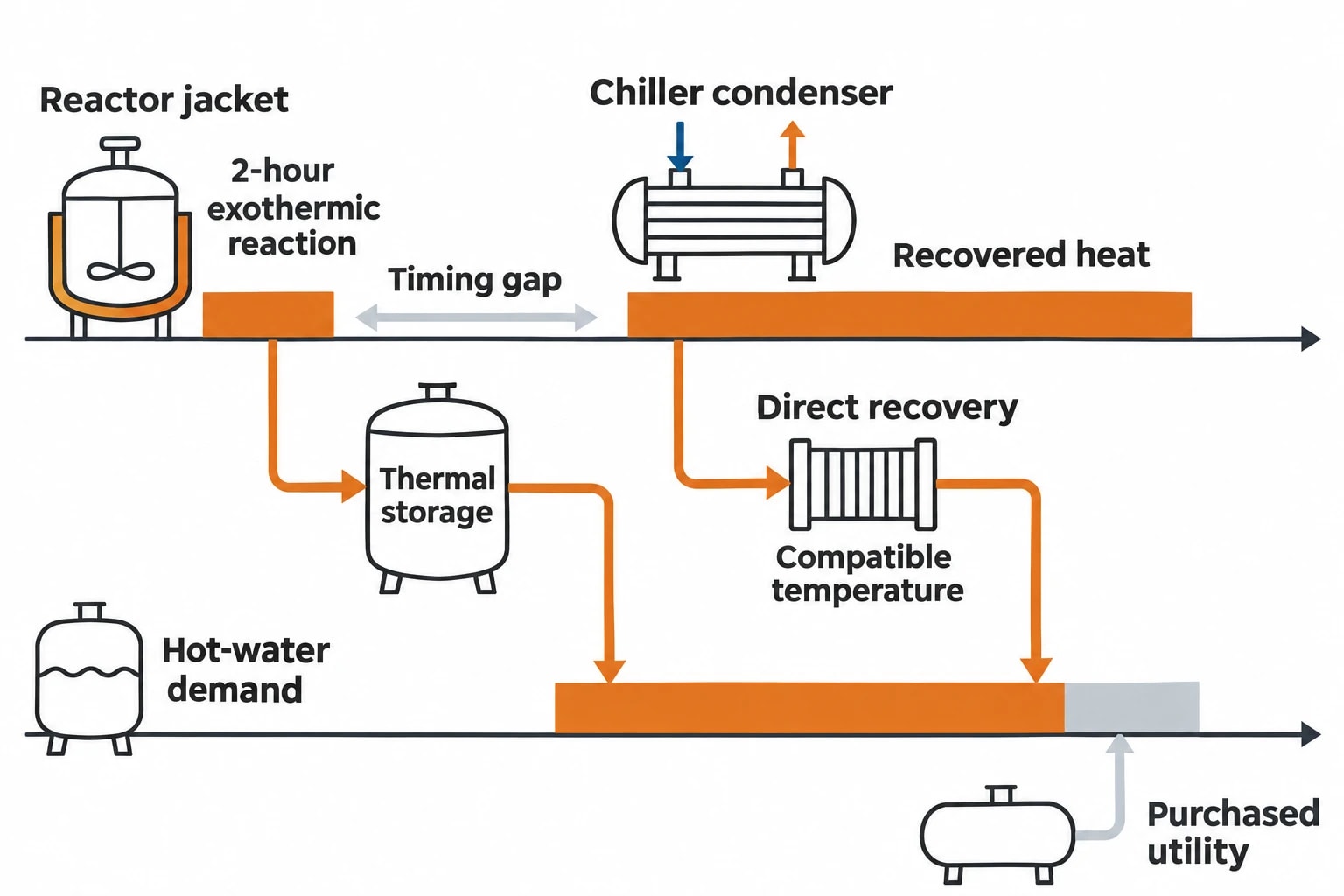
Pharmaceutical manufacturing often operates heating and cooling systems at the same time. A reactor jacket may reject heat during an exothermic batch stage while another area needs hot water for washing, cleaning or building heating. Chillers reject condenser heat while boilers or electric heaters generate low-temperature hot water elsewhere on site.
These simultaneous duties create the opportunity. Recovery displaces purchased steam, gas or electricity where a usable heat source and compatible demand overlap.
Batch production changes the recovery calculation
Batch plants require more than annual utility totals. Heat availability changes during charging, heating, reaction, cooling, discharge, cleaning and downtime. A cooling load can be substantial in annual terms but occur only during short campaign windows.
A reactor may reject heat for two hours during a controlled exothermic reaction. The intended hot-water demand may occur later during a clean-in-place cycle. Direct heat recovery cannot capture the full theoretical benefit unless those profiles overlap, the process sequence changes within approved operating limits, or thermal storage bridges the timing gap.
The analysis should identify:
- Batch recipes, product families and campaign schedules
- Reactor jacket heating and cooling profiles
- Steam, condensate and flash-steam flows
- Chilled-water supply and return temperatures
- Chiller condenser heat rejection
- Washer, steriliser and clean-in-place demand
- Purified-water, WFI and clean-steam operating patterns
- HVAC exhaust conditions and seasonal loads
- Cleaning windows, shutdowns and maintenance isolation periods
This evidence distinguishes an attractive diagram from a recovery duty that can run reliably in production.
Low-temperature heat is often the practical starting point
The quickest schemes often use heat rejected through cooling towers, chiller condensers, warm effluent or ventilation exhaust. That energy may not meet a high-temperature process requirement directly, yet it can preheat water or reduce the load on another utility system.
Potential receiving duties include non-product-contact hot-water circuits, boiler make-up water, wash-water preheat, space heating and selected feedwater applications. The final choice depends on temperature, hygiene requirements, contamination risk, operating hours and utility quality.
Direct recovery through a heat exchanger usually offers the simplest capital case when source and sink temperatures are compatible. An industrial heat pump can raise recovered heat to a more useful temperature, but adds electrical demand, capital cost, controls work and qualification scope.

Map every energy and material flow in your process with detailed heat and mass balance calculations — the foundation for any optimisation or design project.
Build a time-resolved heat and mass balance
A robust project starts by defining a boundary that includes both the heat source and intended heat consumer. The boundary may cover one process skid, a production suite, the central utility plant or an entire manufacturing campus.
The balance must also capture energy penalties. A steam reduction can coincide with increased pumping, altered chiller operation, lower condensate return or heat-pump electricity consumption. These effects determine the real saving.
Create a single source of truth for utility data
Piping and instrumentation diagrams, equipment schedules, historian records, utility invoices and batch records provide the evidence base. None is complete on its own. Temperature instruments may be poorly positioned, flow data may be absent, and production records often lack the utility profile needed to explain a batch cycle.
The engineering output should be a process flow diagram supported by stream tables. Each relevant stream needs a defined fluid, flow rate, inlet and outlet temperature, pressure, run time, data confidence and connection to a process or utility system.
| Stream or duty | Evidence required | Decision supported |
|---|---|---|
| Reactor cooling jacket | Flow, supply and return temperature, batch timing | Recoverable heat during reaction and cooldown |
| Chiller condenser loop | Condenser-water flow, temperature, chiller load | Hot-water recovery potential and chiller impact |
| Steam condensate | Pressure, temperature, return route, contamination risk | Feedwater preheat or flash-steam use |
| Hot-water demand | Flow, target temperature, hygiene classification | Compatible receiving duty |
| Clean utility system | Operating profile, critical parameters, segregation arrangements | GMP impact and change-control scope |
For a reactor cooling circuit, the balance should separate jacket water from central chilled water and refrigeration duty. For steam systems, it should distinguish plant steam, clean steam, condensate, flash steam and condensate return. These streams carry different energy values and quality implications.
Test real operating conditions
A representative production week is a useful starting point, but it should not be the only scenario. The heat and mass balance should examine high-production periods, low-output operation and seasonal extremes affecting chillers and HVAC systems.
This work reveals constraints early. A recovery loop might perform well during one product campaign but be unavailable during another because a line is cleaning, a utility is isolated or the source temperature falls below the heat exchanger’s useful range.
The resulting load profiles should show:
- Available heat by temperature band and time period.
- Receiving demand by temperature band and time period.
- Hours of direct overlap.
- Potential recovery with and without thermal storage.
- Hours when the system will bypass recovery.
A proposal built on these conditions gives operations, engineering and quality teams a common basis for design review.
Select heat-recovery routes that protect GMP operation
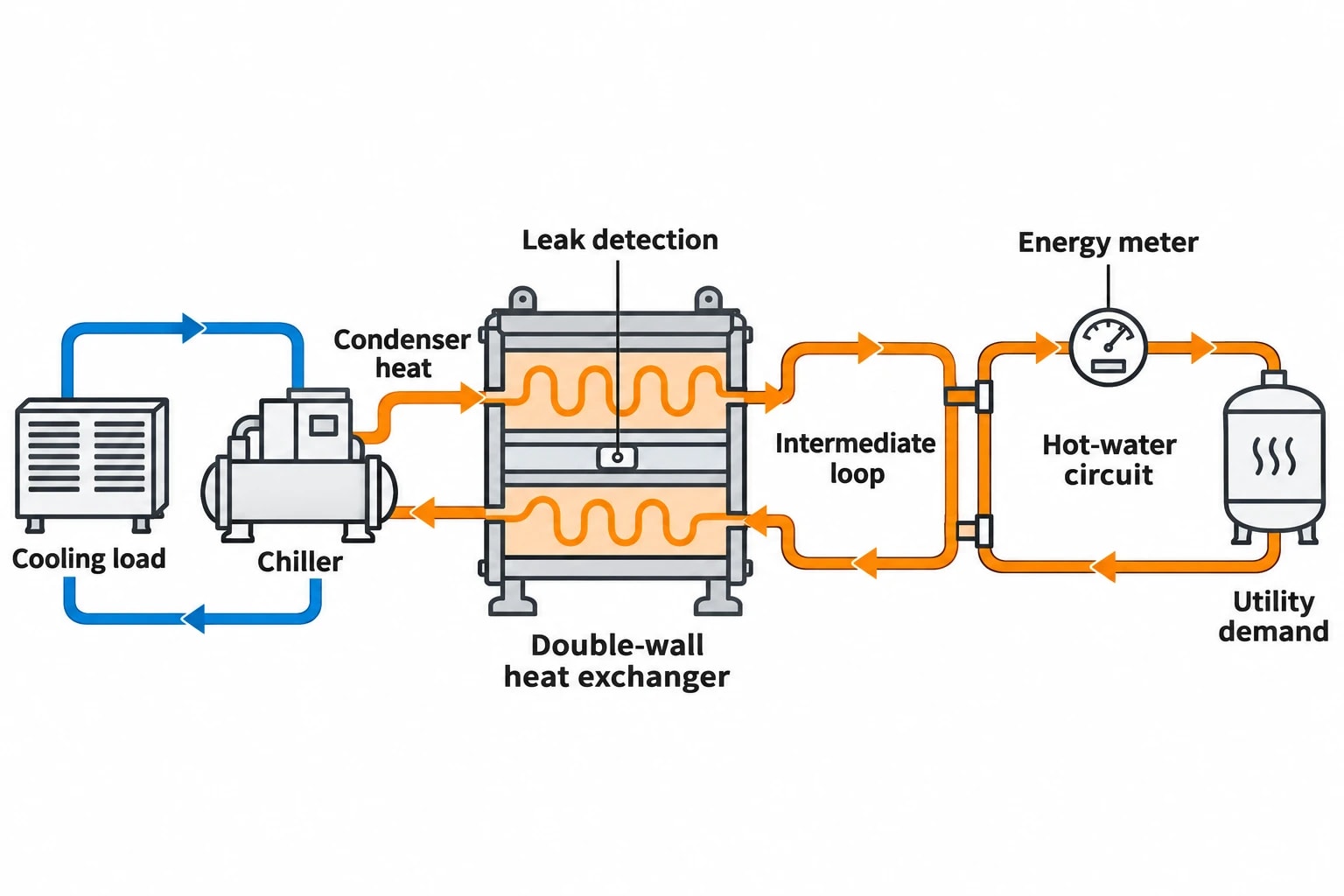
Heat recovery in pharmaceutical manufacturing should be designed around containment, segregation and maintainability. Many practical projects retain recovered heat within separate non-product-contact utility loops.
Recover chiller condenser heat for hot-water demand
Chillers reject heat whenever they remove process or building heat. A heat-recovery exchanger can transfer a proportion of that heat to a hot-water circuit where simultaneous demand exists.
This route can reduce boiler fuel use or electric-water-heater demand, but the calculation must assess the chiller as well as the heat consumer. Raising condenser-water temperature may change compressor energy consumption. The project case needs to calculate both recovered heat value and any refrigeration penalty.
Where higher delivery temperatures are required, a heat pump may improve the temperature match. Its economics depend on actual source and delivery temperatures, electrical tariff, run hours and the fuel displaced. Catalogue performance figures offer a preliminary screen. Metered site performance supports the final business case.
Use condensate and flash steam carefully
Hot condensate can preheat boiler make-up water or another compatible utility stream. Flash steam generated when high-pressure condensate drops to lower pressure can meet a lower-pressure steam demand where both are available at the same time.
Pharmaceutical sites should not treat clean-steam condensate, process condensate and plant-steam condensate as interchangeable. The receiving use, pipework segregation, material compatibility and credible contamination routes determine whether recovery is appropriate.
An indirect arrangement may be appropriate where the quality-risk assessment identifies a cross-contamination pathway. Depending on the service, the design team may consider an intermediate loop, double-wall heat exchanger or another engineered separation arrangement. Inspection access, leak detection and maintenance isolation should form part of the design basis.
Recover HVAC heat without compromising controlled areas
Air-handling systems can reject significant heat in facilities with high outside-air rates and tightly controlled internal conditions. Sensible heat recovery can reduce heating demand where airflow design and contamination controls permit it.
The energy balance alone is insufficient. The design assessment should cover pressure cascades, room classification, filtration, condensate management, cleanability, maintenance access and fault response. A recovery device must preserve the environmental conditions that support manufacturing.
Add thermal storage only where it extends useful run hours
Thermal storage can transfer recovered heat from a predictable batch-cooling peak to a later hot-water demand. It may be useful where campaigns produce regular recovery periods but utility demand occurs after the reactor or process train has completed its cooling phase.
Storage also introduces heat losses, space requirements, water-treatment needs, instrumentation and additional maintenance. Engineers should size a buffer vessel from measured source and sink profiles. Generic storage rules can overstate usable recovery and inflate installed cost.

Map every energy and material flow in your process with detailed heat and mass balance calculations — the foundation for any optimisation or design project.
Build a payback model that finance and operations can trust
Simple payback provides a useful first investment screen, especially when recovered heat directly displaces purchased fuel or electricity. A decision-grade case needs a fuller view of installed cost, production variability and operating risk.
The World Bank Group and IFC example reports a complete package rather than savings from a single technology. The business case should make the same distinction.
Include the full installed cost
The equipment quotation rarely represents the full cost of a GMP-regulated recovery scheme. A realistic capital model includes:
- Heat exchangers, pumps, valves, controls and instrumentation
- Pipework, supports, insulation and access arrangements
- Electrical works and control-system integration
- Shutdown, tie-in, commissioning and production support
- Water treatment and utility-quality controls
- Design review, hazard assessment and project management
- Change control, qualification protocols and test execution
- Calibration, maintenance plans and procedure updates
- Contingency for routing, access and production constraints
Teams should separate the cost of heat recovery from costs that correct pre-existing asset-condition issues. Finance teams can then assess the incremental investment, while maintenance teams retain visibility of asset-renewal work.
Value the utilities actually displaced
Recovered heat has different value depending on the energy source displaced. A loop replacing gas-fired boiler duty will generate a different saving from one replacing electric resistance heating. A scheme that reduces boiler load and changes chiller performance should value both effects and deduct additional pump or heat-pump electricity.
Annual run hours should come from historian data, campaign schedules and production plans rather than a generic assumption. The financial model should test reduced output, changed product mix, lower utility prices, maintenance bypass periods and partial availability.
A useful investment paper presents a base case and a conservative case. The conservative case should use defensible operating hours and include expected bypass conditions. This makes the project more resilient to normal production variation.
Meter the recovered energy after commissioning
ISO 50001:2018 provides a framework for energy-performance objectives, measurement and continual improvement. For a heat-recovery project, the practical requirement is clear: establish a representative baseline, meter key energy flows where feasible and define how output changes will be treated.
Batch sites may normalise performance against batch count, recipe family, kilograms processed, sterilisation cycles, WFI demand or operating hours. Chiller and HVAC projects may also need ambient temperature in the performance assessment.
The handover report should track recovered heat, displaced steam or fuel, additional electricity, production output, bypass hours and maintenance activity. That record supports future optimisation and exposes performance deterioration before it erodes the project return.
GMP change control shapes the engineering route
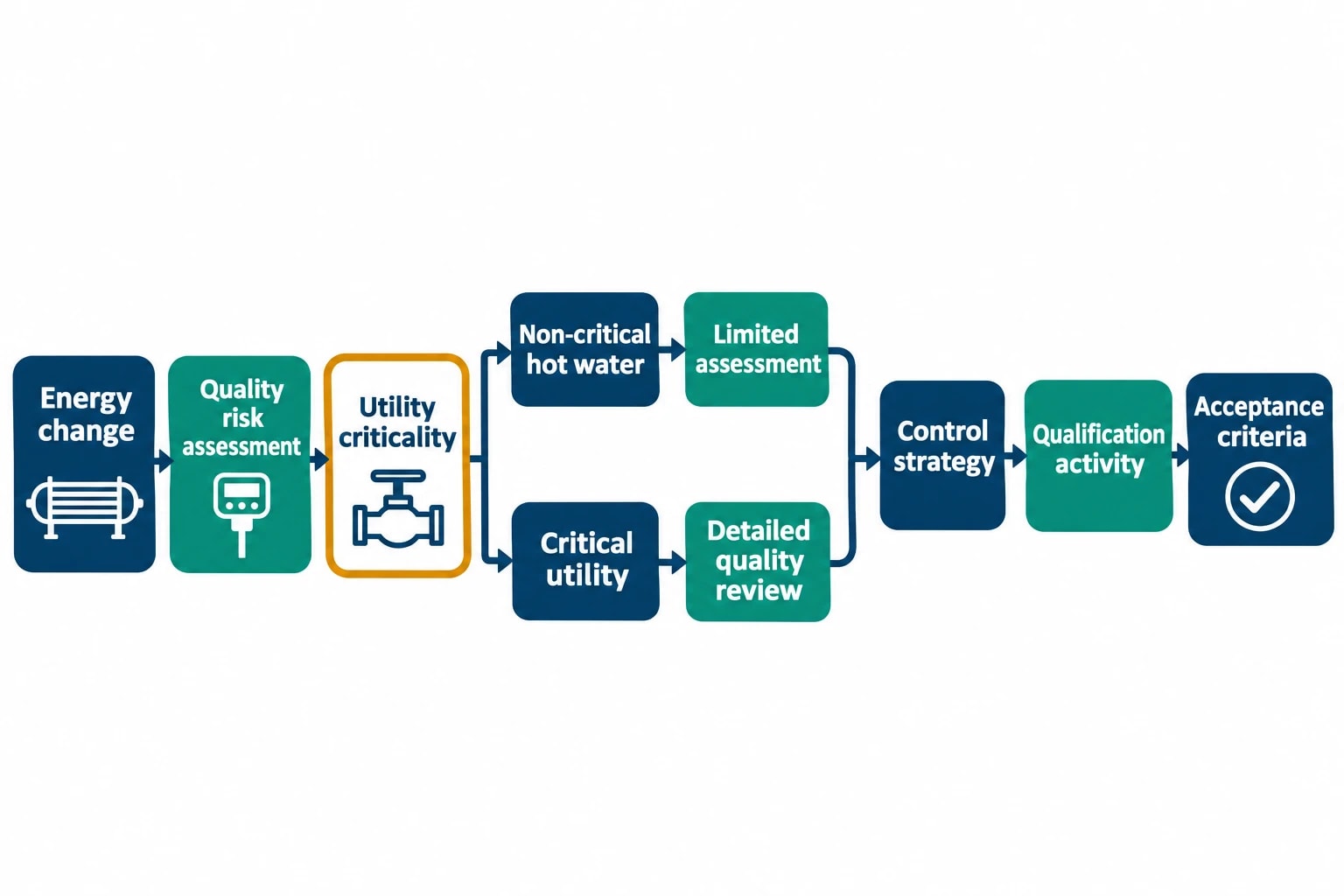
Energy efficiency in pharmaceutical manufacturing operates within the pharmaceutical quality system. A new heat exchanger, altered condensate route, revised utility setpoint or changed batch heating profile may affect systems that support product quality.
EU GMP Annex 15, section 11.4 requires quality risk management to assess the potential effects of planned changes on product quality, the pharmaceutical quality system, documentation, validation, regulatory status, calibration, maintenance and other systems. The assessment should identify necessary verification, including qualification, requalification or revalidation.
Bring quality assessment into concept design
The quality function needs a clear description of the energy change before equipment procurement. The initial assessment should identify affected utilities, critical parameters, potential failure modes, alarms, records, acceptance criteria and required qualification activity.
A loop serving non-critical building hot water may need a limited assessment. Changes affecting clean steam, WFI, purified water, cleanroom conditions or validated process temperatures require a more detailed quality review. The scope follows risk, system criticality and the site’s approved procedures.
Key review questions include:
- Does the design alter a validated operating range or process setpoint?
- Could a heat-exchanger failure create a contamination or utility-quality risk?
- Does the control strategy move the receiving utility to a safe condition after pump, sensor or power failure?
- Are control instruments calibrated and traceable?
- Does maintenance access affect cleanroom classification or production availability?
- Which procedures, training records and preventive-maintenance plans require revision?
- Which commissioning and requalification tests demonstrate continued fitness for purpose?
Design for maintenance, bypass and verification
A recovery loop needs defined normal, bypass, isolation and fault modes. Automatic bypass can protect the receiving utility when source temperature is insufficient, a heat exchanger is isolated or an abnormal condition occurs. Commissioning should test each mode against approved acceptance criteria.
Maintenance affects lifetime energy performance. Fouling, valve deterioration, pump reliability and sensor drift can reduce recovery over time. Instrument locations should support fault diagnosis, and isolation points should allow maintenance with minimal impact on production.
HSE identifies fouling, overheating, leakage, tube vibration and tube rupture among heat-exchanger failure modes that can affect safety. These issues should be addressed through materials selection, inspection, monitoring, isolation and maintenance planning.
A practical route from survey to controlled handover
A pharmaceutical heat-recovery project progresses most effectively when engineering, utilities, maintenance and quality teams work from the same evidence.
- Define the process and utility boundary.
- Gather batch, utility, maintenance and quality-system data.
- Validate measurements and close material data gaps.
- Develop time-resolved heat and mass balances.
- Identify heat sources, heat sinks and temperature matches.
- Screen direct recovery, thermal storage and heat-pump options.
- Complete GMP change-control and qualification impact assessment.
- Develop installed-cost, base-case and conservative-case savings models.
- Select metering points and performance indicators.
- Commission, verify, document and hand over the controlled system.
A credible proposal identifies a measured heat source, compatible demand, verified hours of overlap, a defined quality-risk strategy and a metered performance plan. These elements turn pharmaceutical heat recovery into an investment case that can deliver fast payback without compromising validated manufacture.
This article reflects the independent analysis and editorial opinion of EnerTherm Engineering. Product names, trademarks, and brands mentioned belong to their respective owners. EnerTherm Engineering is not affiliated with, endorsed by, or a licensee of any third-party software or product mentioned unless explicitly stated.

Managing Director — EnerTherm Engineering
Dr. François Pierrel is Managing Director of EnerTherm Engineering with over two decades of expertise in thermal design, heat transfer, and industrial energy optimisation. He holds a PhD in Heat Transfer from Cranfield University and a Post-Doctorate from Heriot-Watt University.
