Why WFI Loops Stay Above 70°C in GMP Facilities
A heat and mass balance of hot-loop insulation, cooling loads and WFI quality controls.
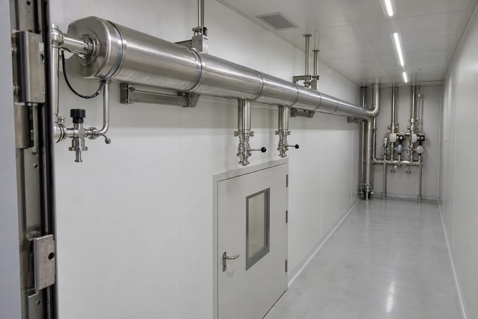
A Water for Injection (WFI) loop is a pharmaceutical clean-utility distribution system that continuously circulates bulk WFI, commonly above 70°C, to minimise microbial growth and biofilm risk while delivering validated water to production points of use.
That operating temperature has a visible utility cost. Hot WFI loses heat through pipework, valve clusters, tanks, supports and branches around the clock. The resulting demand appears as clean-steam consumption, electrical load at vapour-compression generation plants and, in some cases, additional cooling demand.
EU GMP Annex 1 explains why facilities accept that duty. Clauses 6.7, 6.9 and 6.10 link water-system design to biofilm prevention, turbulent flow and storage or distribution arrangements that minimise microbial growth. Constant circulation above 70°C is the stated WFI example. The engineering objective is to preserve that qualified microbial-control strategy while removing avoidable steam, electricity, water and cooling loads.
EU GMP Annex 1 explains why hot WFI circulation persists
Above 70°C is an established microbial-control measure
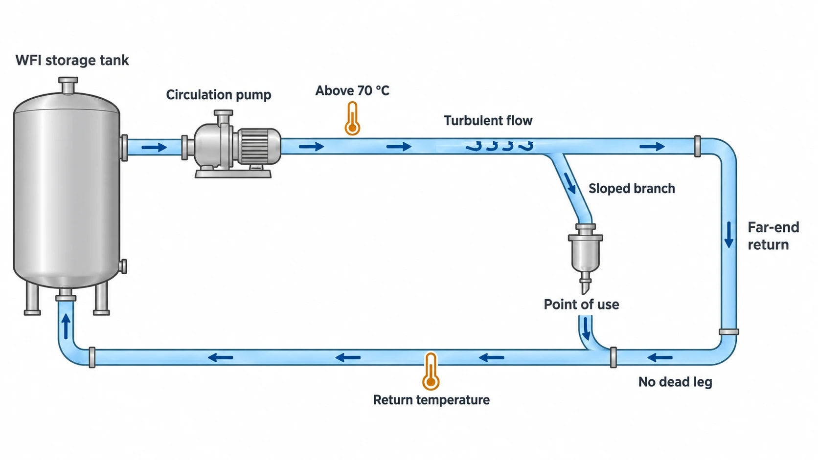
EU GMP Annex 1 clause 6.10 states that WFI should be stored and distributed in a manner that minimises the risk of microbial growth, giving constant circulation above 70°C as an example.
For hot WFI systems, temperature, continuous movement and sanitary construction work together. Storage tanks often operate above the minimum loop temperature to accommodate distribution losses. Return temperature is therefore a useful indicator at the far end of the WFI loop. A sustained fall can indicate that the system no longer operates within its qualified thermal range.
Annex 1 does not prescribe an identical setpoint for every installation. The manufacturer must define and qualify the operating range, supported by a contamination-control strategy. A site may choose another distribution concept, but it must demonstrate equivalent control of microbial risk, biofilm formation, sanitisation and recovery after intervention.
Flow, drainage and branch design remain inseparable from temperature
Clause 6.7 requires water treatment and distribution systems to minimise particulate contamination, microbial contamination or proliferation, pyrogens and biofilm formation. It identifies pipe slope for drainage and avoidance of dead legs. Clause 6.9 requires turbulent water flow through distribution pipework to reduce microbial adhesion and subsequent biofilm formation.
Heat alone cannot correct poor hygienic design. A 75°C WFI loop with poorly drained branches, stagnant sample lines or redundant take-offs still carries quality risk. It also carries a larger thermal load because each branch adds wetted volume, stainless-steel surface, fittings and insulation discontinuities.
The operating question is broader than, “Can the loop temperature be reduced?” Engineers need to establish whether the qualified system controls microbial risk at the worst-case point of use, during low demand, after maintenance and through seasonal ambient changes.

Map every energy and material flow in your process with detailed heat and mass balance calculations — the foundation for any optimisation or design project.
Why hot WFI loops consume continuous utility energy
Distribution heat loss continues outside production hours
A hot WFI loop loses heat whenever its surface temperature exceeds the surrounding air temperature. That duty persists during weekends, planned shutdowns and low-production periods if circulation continues.
A useful heat and mass balance separates three categories of load:
- Continuous heat loss from distribution pipework, fittings, tank surfaces and equipment.
- Reheating duty associated with WFI draw-off and replacement water.
- Intermittent loads from start-up, sanitisation, cool-down, maintenance and regeneration.
The first category is often underestimated. Straight pipework is easy to count from a layout drawing. Valve stations, flanges, flowmeters, pressure instruments, tank nozzles, removable covers and pipe supports are harder to quantify. Their combined exposed area can be material in a dense pharmaceutical utility corridor.
For illustration, a 400 m route with an assessed average loss of 12 W per metre has a continuous heat loss of 4.8 kW before tank and fitting losses. Over 24 hours, that represents 115.2 kWh of delivered heat. This is an illustrative result rather than a design allowance. Diameter, insulation thickness, ambient temperature, air movement, pipe supports, valve density and operating temperature all alter the outcome.
BS EN ISO 12241:2022 provides calculation rules for heat-transfer properties in industrial installations, including thermal bridges. The UK Energy Technology List identifies pipework, fittings, tanks and vessels as distinct insulation categories, which matters where valve matrices dominate local heat loss.
Draw-off changes both the water and thermal balance
Each WFI withdrawal creates a mass-balance event. The generation system must replace the delivered volume, and the storage and distribution system must restore its operating temperature. Large rinses, cleaning operations and simultaneous production demand can therefore drive a different heat load from static distribution loss.
The water balance should identify:
- WFI generated and transferred to storage.
- WFI delivered to each production area.
- Water discharged through samples, flushing and maintenance.
- Membrane-system concentrate or reject water, where applicable.
- Tank overflows, leaks and unplanned losses.
- Water used during sanitisation and post-sanitisation rinsing.
A WFI loop that appears inefficient may have a water-loss problem rather than an insulation problem. A leaking point-of-use valve, oversized branch-flushing routine or redundant connection increases WFI generation, heating duty and the quantity of water the site must treat or discharge.
Tank heating and return temperature reveal the operating pattern
Tank level, supply temperature, return temperature, recirculation flow and heating duty should be trended alongside production demand. These values distinguish steady loss from event-driven load.
A stable recirculation flow with rising heating duty during a cold spell points to heat loss to the surroundings. A tank-level decline combined with high generator run time may indicate greater draw-off, leakage or flushing. A falling WFI-loop return temperature during peak use can identify a capacity shortfall in heating, distribution or recirculation.
This data reconciles the heat and mass balance used to assess insulation, tank heating capacity, generator operation and distribution changes.
WFI system design and energy optimisation begin with sanitary hydraulics
Turbulent flow must be demonstrated at the real operating condition
Annex 1 requires turbulent flow, but a nominal pump duty on a datasheet does not prove that condition across the WFI loop. The hydraulic review needs actual internal diameters, water temperature, recirculation rate, fluid properties, pipe lengths, pressure losses and the worst-case configuration of simultaneous point-of-use demand.
The return leg and remote branches need the same attention as the main ring. Flow conditions can change after a pump replacement, pipework extension, altered valve arrangement or variable-speed-drive adjustment. A reduced pump speed may save electricity while undermining the qualified hydraulic condition.
The target is a recirculation rate that meets the qualified flow requirement without excess throttling or unnecessary pump head. Excessive pump head raises electrical demand and adds heat to the water. Undersized pipework can introduce high pressure losses and poor distribution. Oversized pipework increases hold-up volume, exposed surface area and warm-up time.
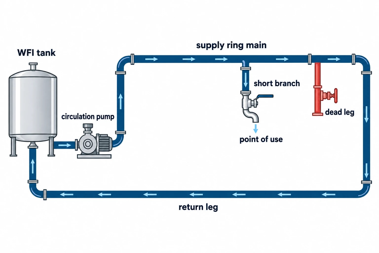
Dead legs add quality risk and thermal burden
Dead legs prevent reliable water renewal and complicate temperature control. They can cool more quickly than the main WFI loop, retain water during low demand and make sanitisation harder to demonstrate. Their energy effect is less dramatic than a long uninsulated ring main, but removal can improve thermal performance, hygienic design and validation effort.
A distribution survey should classify every branch by operational purpose:
- Active production connection.
- Validated sample point.
- Temporary equipment connection.
- Isolated legacy connection.
- Redundant branch suitable for removal.
The survey should also identify low points, poor pipe slope, inaccessible valves and branch sections requiring repeated flushing. These findings belong in the heat and mass balance because they affect water loss, exposed surface area, hold-up volume and sanitisation demand.
Insulation quality deserves field verification
Installed insulation can perform differently from its drawing specification. Maintenance work can leave valve covers off, damage jackets, compress insulation around supports or create gaps at flanges and instruments. Wet insulation also changes thermal performance and may introduce condensation or cleanability concerns.
A site survey can combine infrared observations with dimensional checks, insulation-thickness measurements, ambient conditions and operating temperatures. Infrared images help identify locations for detailed inspection. Heat-loss calculations should use confirmed geometry and material properties rather than surface-temperature images alone.
Any insulation upgrade requires GMP assessment. The selected solution must preserve access for maintenance, cleanability, drainability, inspection and temperature mapping. Removable covers can reduce loss from valves and flanges where the materials and attachment method suit the local environment.

Map every energy and material flow in your process with detailed heat and mass balance calculations — the foundation for any optimisation or design project.
Distillation and membrane WFI generation change the utility profile
Generation technology does not remove hot-loop duty
Ph. Eur. monograph 0169 permits bulk WFI production by distillation or by a purification process equivalent to distillation, including reverse osmosis combined with suitable techniques such as electrodeionisation, ultrafiltration or nanofiltration. The generation route changes the upstream utility balance. It does not eliminate distribution heat loss where a site selects hot WFI storage and circulation.
A membrane-based WFI system can reduce reliance on plant steam, while a distillation-based system provides a thermal route to water production. Both can supply a hot WFI loop. That loop should therefore be modelled as a common downstream load when comparing generation technologies.
ISO 22519:2023 provides a benchmark for assessing the design, operation and performance of membrane-based WFI generation systems. Its scope covers new membrane systems and excludes distillation and validation. It can inform the generator assessment, while site qualification and the Annex 1 contamination-control strategy remain separate responsibilities.
Multi-effect and vapour-compression distillation require different balances
Multi-effect distillation uses heat across successive effects. Its balance should include feed water, WFI output, plant steam, condensate recovery, cooling demand, start-up losses and operating hours. Condenser performance, steam pressure and part-load operation can materially affect the result.
Vapour-compression distillation recycles vapour energy through mechanical or thermal compression, changing the split between electricity and steam. A comparison based only on generator nameplate capacity can mislead. Engineers need measured or vendor-guaranteed duty at the required WFI rate, inlet conditions and turndown.
Membrane WFI systems bring reject-water and sanitisation loads
An RO, CEDI and ultrafiltration train requires a complete water balance from feed-water intake to qualified WFI output. The principal streams include feed water, permeate, concentrate, sanitisation water, rinse water and cleaning-related discharge. Electrical demand includes high-pressure pumping, CEDI and ancillary equipment.
Recovery matters, but it cannot become the sole optimisation criterion. Higher recovery changes the concentration of dissolved species and foulants in the reject stream. That can affect pretreatment duty, cleaning frequency, membrane condition and system availability. The meaningful comparison is lifecycle utility demand per qualified cubic metre of WFI, assessed alongside quality performance and operational resilience.
| System area | Distillation-led WFI | RO/CEDI/UF-led WFI |
|---|---|---|
| Main energy input | Steam or electrical compression duty | Electricity for pumps, CEDI and ancillary equipment |
| Principal water-loss term | Start-up, maintenance and process-specific blowdown | RO concentrate or reject water |
| Heat rejection | Condenser cooling requirement may apply | Equipment heat and configuration-specific cooling loads |
| Key operational sensitivity | Steam conditions, condensate return, cooling conditions and turndown | Feed-water quality, recovery, pretreatment and membrane condition |
| Hot-loop energy demand | Pipework, fittings, tank and branch heat loss | Pipework, fittings, tank and branch heat loss |
Building a heat and mass balance for a WFI upgrade
Establish a representative operating baseline
A reliable model needs data from production and non-production periods. One day of steady operation rarely captures peak draw-off, campaign changes, sanitisation or idle losses.
The baseline should include WFI generation rate, tank level, supply and return temperatures, recirculation flow, steam use, electricity use, condensate return, cooling-water use where relevant, generation run time, production draw-off and water discharged from flushing or maintenance. Data should cover defined operating modes rather than being averaged into one annual number.
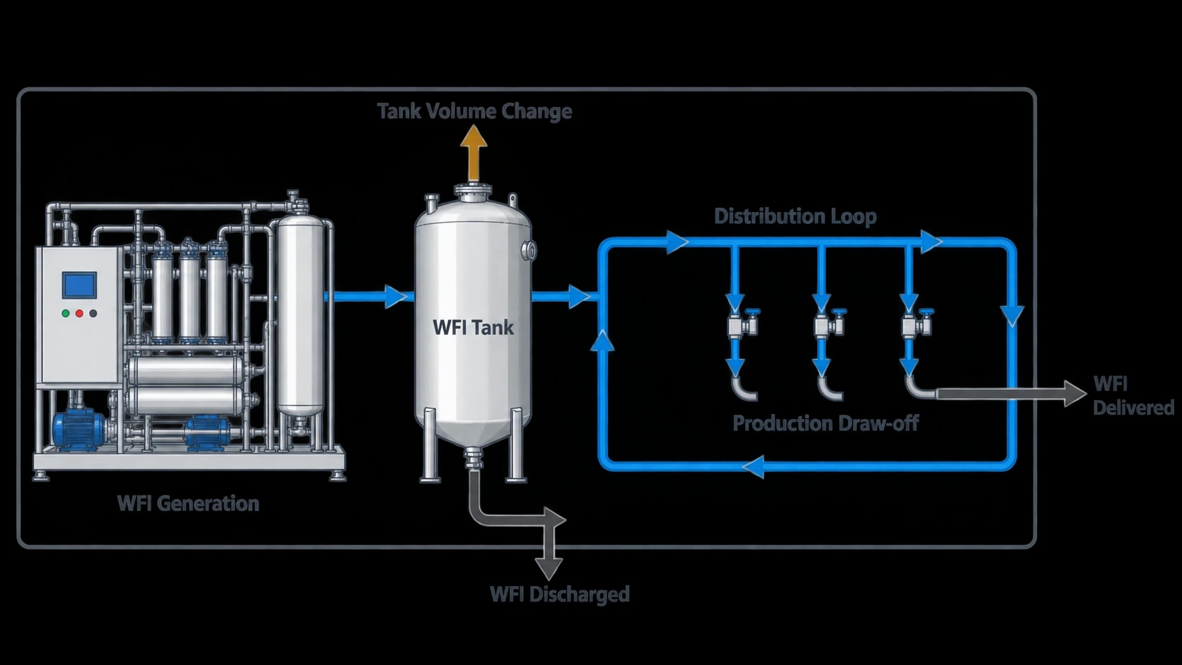
The model should reconcile WFI generated with WFI delivered, discharged and retained in changing tank volume. It should also reconcile delivered heating duty with pipework, tank, fitting and operational loads. A material mismatch can expose unmetered draw-off, failed traps, insulation damage, inaccurate flowmeter scaling or a missing utility connection.
Test changes against the qualified operating envelope
Once the baseline is credible, engineers can assess individual measures and combined packages.
- Repair damaged insulation and provide suitable covers for high-loss fittings.
- Remove redundant branches and correct drainability defects.
- Confirm recirculation flow against the qualified turbulent-flow requirement.
- Review pump control, differential pressure and throttling losses.
- Match generation capacity and standby operation to actual WFI demand.
- Recover condensate where the clean-steam arrangement and quality assessment permit.
- Compare distillation and membrane options using water, steam, electricity, cooling and sanitisation loads together.
Any change to WFI-loop temperature, circulation regime, sanitisation frequency or operating limits requires formal GMP change control, risk assessment and requalification. The energy model shows the size and location of the utility load; it cannot substitute for qualification evidence.
The practical route to lower WFI energy demand
A credible heat and mass balance separates static distribution loss, WFI draw-off and generation-related utility loads. It gives engineering, quality and energy teams a common basis for reducing consumption without weakening the qualified conditions that protect WFI quality.
This article reflects the independent analysis and editorial opinion of EnerTherm Engineering. Product names, trademarks, and brands mentioned belong to their respective owners. EnerTherm Engineering is not affiliated with, endorsed by, or a licensee of any third-party software or product mentioned unless explicitly stated.

Managing Director — EnerTherm Engineering
Dr. François Pierrel is Managing Director of EnerTherm Engineering with over two decades of expertise in thermal design, heat transfer, and industrial energy optimisation. He holds a PhD in Heat Transfer from Cranfield University and a Post-Doctorate from Heriot-Watt University.
