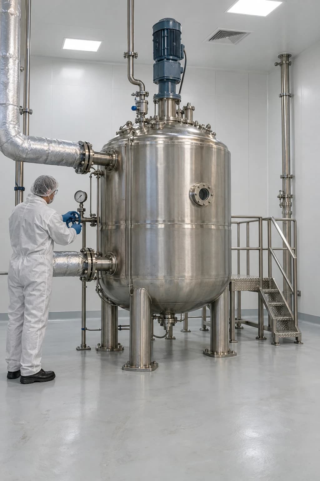
When Cooling Fails in an Exothermic Batch Reactor
Calorimetry establishes heat release and TMR for alarms, trips and relief design.
Exothermic reaction temperature control manages reaction heat generation so that it remains below the heat a reactor can remove, preventing a temperature excursion, loss of product quality and possible overpressure. In a pharmaceutical batch reactor, that margin can disappear quickly after a utility interruption, agitator failure, excessive reactant charge or a warmer-than-specified feed.
The Health and Safety Executive defines thermal runaway as the point at which reaction heat generation exceeds heat loss to the surroundings. This is especially relevant to batch and semi-batch processing because reaction composition, reactor inventory and heat-transfer demand change throughout the batch. A jacket that provides adequate cooling at the start of an addition may be unable to control the peak reaction rate later in the operation.
For GMP-regulated drug-substance manufacture, the consequence extends beyond plant safety. A temperature excursion can alter impurity formation, selectivity, crystallisation behaviour, solvent composition or downstream filtration performance. The batch record, control strategy and validation evidence must show that the process remained within its approved operating range, or provide the factual basis for an investigation and quality decision.
Why exothermic reaction temperature control can fail suddenly
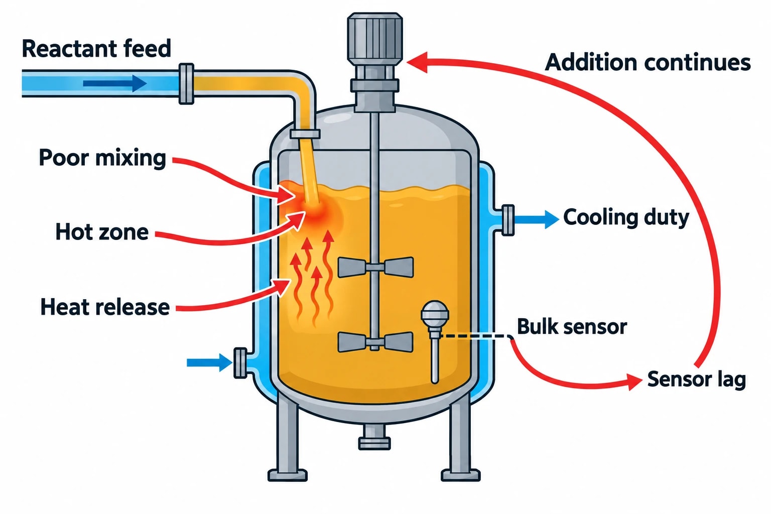
Cooling duty has a physical limit
A reactor jacket, internal coil or external recirculation loop removes heat through finite heat-transfer area and temperature driving force. Its actual duty depends on coolant supply temperature, coolant flow, fouling, jacket pressure, reactor fill level, agitation and the physical properties of the batch.
During an exothermic addition, heat release may rise more rapidly than the available cooling duty. The batch temperature then increases. Many reactions accelerate as temperature rises, producing more heat and reducing the time available for intervention.
The critical engineering question is not whether a cooling utility is available. It is whether the reactor can remove heat at the highest credible rate of generation under the conditions applying at that point in the batch.
Batch operation creates moving conditions
A continuous process can settle around a defined operating state. A batch reactor does not. Its thermal behaviour changes with each charge, hold, addition, temperature ramp and solvent-removal step.
The factors that commonly change during a pharmaceutical reaction include:
- Reactor liquid mass and fill level
- Heat capacity and viscosity of the mixture
- Concentration of reactive species
- Jacket temperature driving force
- Agitator power and mixing quality
- Addition rate and feed temperature
- Vapour generation and condenser duty
- Heat-transfer performance as solids form or viscosity increases
A jacket control valve may show its expected opening position while the process loses control. Restricted coolant flow, high utility return temperature, a partially blocked jacket circuit or poor agitation can remove thermal margin without generating a separate alarm.
Agitation loss changes more than mixing
Loss of agitation can create local regions of high reactant concentration and temperature. It also reduces heat transfer at the reactor wall and can delay the temperature sensor response relative to the hottest part of the batch. A single bulk-temperature indication may therefore understate the severity of a developing excursion.
This matters during feed-controlled reactions. If the control system continues an addition because the measured bulk temperature remains below its setpoint, reactant can accumulate in poorly mixed liquid. Restored agitation may then expose the accumulated reactant to favourable reaction conditions and release heat rapidly.

Map every energy and material flow in your process with detailed heat and mass balance calculations — the foundation for any optimisation or design project.
Foreseeable cooling-failure scenarios for batch reactors
HSE guidance identifies cooling failure, loss of agitation, reactant addition rate and reactant temperature as foreseeable worst-case scenarios for batch and semi-batch reactors. Each should be evaluated against the actual chemistry, equipment design and operating procedure.
| Scenario | Immediate thermal effect | Evidence needed for the assessment |
|---|---|---|
| Loss of chilled-water, brine or glycol supply | Reduced or zero heat removal | Utility failure mode, cooling-loop response and reactor heat-transfer data |
| Reduced coolant flow | Falling jacket duty despite an available utility | Pump curve, valve performance, differential pressure and fouling history |
| Loss of agitation | Lower heat transfer and possible local reactant accumulation | Mixing assessment, agitator trip response and temperature sensor location |
| Addition above the approved rate | Heat generation exceeds planned removal duty | Feed calibration, flow data, control logic and reaction calorimetry |
| Warm reactant charge | Reduced temperature margin before reaction begins | Raw-material temperature range and charging procedure |
| Incorrect reactant concentration | Higher reaction rate or greater total heat release | Raw-material specification, assay data and mass balance |
| Delayed stop of addition | Continued reactant accumulation during an upset | Alarm, trip and valve-closure testing |
Treat utility failure as a process scenario
A utility-failure assessment should include the reactor and utility network. A chiller trip, loss of cooling-tower performance, transfer-pump failure or utility-header pressure drop can affect several vessels at once. The assessment should establish whether the reactor remains protected when shared cooling demand is high.
The relevant time window starts before the utility fully fails. A gradual reduction in cooling flow may permit temperature drift while the process continues to accumulate reactive material. Dynamic modelling should therefore examine both sudden loss and degrading cooling duty.
Treat feed control as a safety function
The reactant addition rate directly controls the rate at which reactive inventory enters the reactor. An automatic feed stop on high temperature, high temperature rate of rise, agitator trip or low cooling-flow condition can prevent further accumulation. The trip setpoint and response time need a defined technical basis rather than a value inherited from a laboratory instruction or prior campaign.
The selected limits should account for sensor lag, valve-closing time, material already in the feed line and residual reaction after the feed stops.
Calorimetry establishes the credible heat-release case
Begin with DSC and DTA screening
Differential scanning calorimetry and differential thermal analysis provide early screening information from small samples. HSE identifies them as common methods for identifying decomposition-onset temperatures and examining the effect of contaminants on thermal stability.
These tests can identify whether a starting material, intermediate, reaction mass or isolated solid has an exothermic decomposition risk. They can also highlight a secondary event above the intended reaction range. Screening does not establish safe plant-scale conditions by itself. Small samples, different thermal histories and different heat-loss conditions limit direct scale-up to a production reactor.
A reaction-hazard programme should examine relevant process materials, including credible off-specification concentrations, hold-time conditions, residues and contamination cases justified by process knowledge.
Use adiabatic calorimetry for runaway behaviour
Adiabatic calorimetry approximates the condition in which the reacting mass retains its generated heat. HSE states that adiabatic calorimeters can provide data on heat-production rate and gas evolution under runaway conditions. This evidence supports assessment of temperature rise, pressure rise and the potential for vessel overpressure.
The resulting work should establish:
- The onset behaviour of the intended reaction and any secondary reaction
- Heat-release rate as temperature and conversion change
- Gas evolution and pressure development
- The effect of concentration, charge ratio and feed accumulation
- The effect of contamination or decomposition where credible
- Time to Maximum Rate, or TMR
- The time available for an emergency action to take effect
HSE defines TMR as the period from runaway onset to the maximum rate of heat generation. It is useful because it connects test data to the practical response time of a feed trip, emergency cooling system, quench addition or relief system.
Link testing to relief and quench design
A relief device must protect against the actual relieving case. For a runaway reaction, this may involve vapour, non-condensable gas, liquid carryover or a two-phase discharge. HSE guidance notes that detailed emergency-relief analysis with experimental testing has become accepted practice for such duties.
Where evidence indicates that cooling and feed isolation cannot control the event within the available TMR, designers may consider emergency cooling, a chemically compatible quench, reaction inhibition, containment or emergency pressure relief. The choice depends on the chemistry and must address downstream consequences, including vent disposal, scrubber capacity, flammability, toxicity and liquid carryover.
A quench system requires more than suitable quench material. It requires adequate inventory, proven compatibility, a reliable injection path, sufficient mixing and a defined response time. HSE notes that direct quenching cools and dilutes reactants, slowing the reaction rate and heat generation to a controllable level.
Build the heat and mass balance around the full batch profile
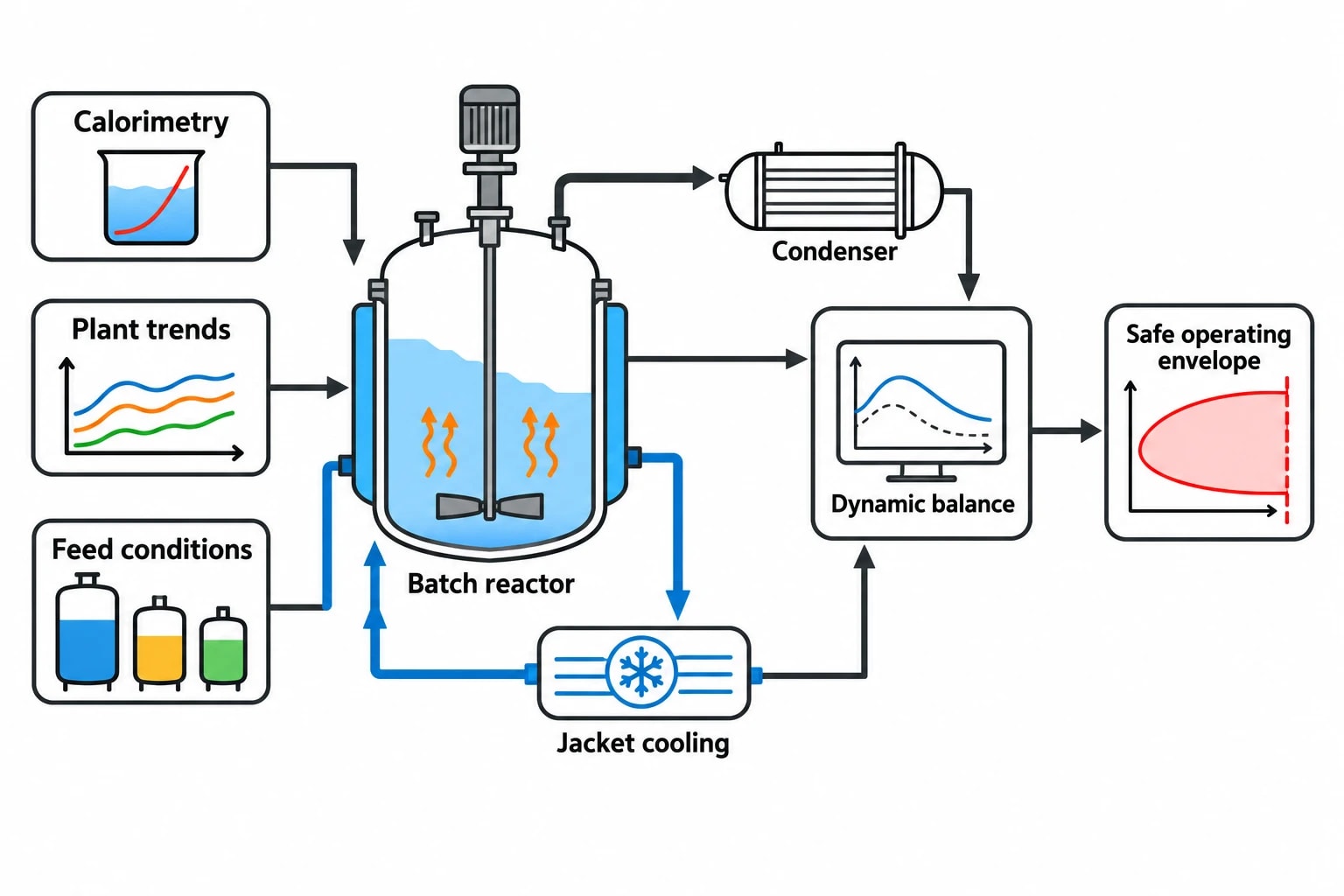
Use a dynamic reactor model
A steady-state heat balance can estimate peak utility demand, but an exothermic batch reactor requires a time-dependent model. The model should track changing reactor inventory, composition, reaction rate, sensible heat, heat-transfer duty and utility conditions through the batch.
Key model inputs include:
- Reactor working volume, material of construction and heat-transfer area
- Batch mass, composition and heat capacity at each stage
- Reaction calorimetry data and reaction kinetics where available
- Reactor heat-transfer performance at relevant fill levels and agitation rates
- Jacket or coil supply temperature, flow and return conditions
- Feed rate, feed temperature, line hold-up and maximum credible overfeed
- Condenser duty and vapour-generation behaviour
- Emergency cooling, quench and relief-system response characteristics
Plant data should challenge the model. Historical batch trends can show actual jacket temperature approach, valve movement, coolant return temperature and response during controlled additions. A model that assumes a constant overall heat-transfer coefficient may overstate available cooling duty when the batch thickens, solids appear or agitation deteriorates.
Identify the safe operating limits
The model and calorimetry package should define a safe operating envelope for the reaction. This normally includes a target temperature, normal operating range, alarm threshold, feed-stop trip threshold and maximum allowable temperature. These values serve different purposes and should not be collapsed into one number.
A target temperature supports consistent product formation. An alarm prompts review and intervention. A trip protects the process before thermal margin is exhausted. A maximum allowable temperature marks the boundary beyond which product quality, process safety or both may be compromised.
The limits also need to cover reactant temperature, addition rate, cooling availability and agitation status. A temperature limit alone cannot control an exotherm if the reaction mass already contains excessive accumulated reactant.

Map every energy and material flow in your process with detailed heat and mass balance calculations — the foundation for any optimisation or design project.
Design a layered temperature-control strategy
Control the normal operation
The normal control layer uses reactor temperature measurement, jacket temperature control and a governed feed rate to maintain the approved reaction profile. A cascade arrangement may improve response where jacket supply conditions vary, provided the design is qualified for the intended duty.
Instrument placement matters. A probe close to a cold wall or feed point can give a misleading indication of bulk conditions. Multiple temperature measurements may be justified for larger reactors, viscous mixtures or reactions with local heat-release risks.
Protect against the credible upset
Protective functions should act on conditions that identify loss of control early enough to be effective. Common initiating conditions include high reactor temperature, high temperature rate of rise, agitator trip, low coolant flow, high jacket return temperature and loss of cooling-utility pressure.
The process-safety assessment should establish the required independence, reliability and proof-testing arrangements for any protective trip. It should also confirm the final action. Stopping feed, placing the jacket on maximum cooling, isolating heating and initiating a quench are materially different responses, with different hazards and validation implications.
Preserve relief as the final physical safeguard
Emergency relief protects equipment integrity when prevention layers do not arrest pressure generation. It does not restore product quality or make an uncontrolled reaction acceptable. The relief basis must include measured reaction and gas-evolution behaviour, relieving temperature and pressure, potential two-phase flow, downstream backpressure and the capability of the disposal system.
HSE advises that the design basis and methodology for relief streams should be documented and incorporated into plant-modification and change procedures. For pharmaceutical facilities, this should form part of the engineering evidence supporting the validated process and site emergency arrangements.
GMP implications of temperature excursions and control changes
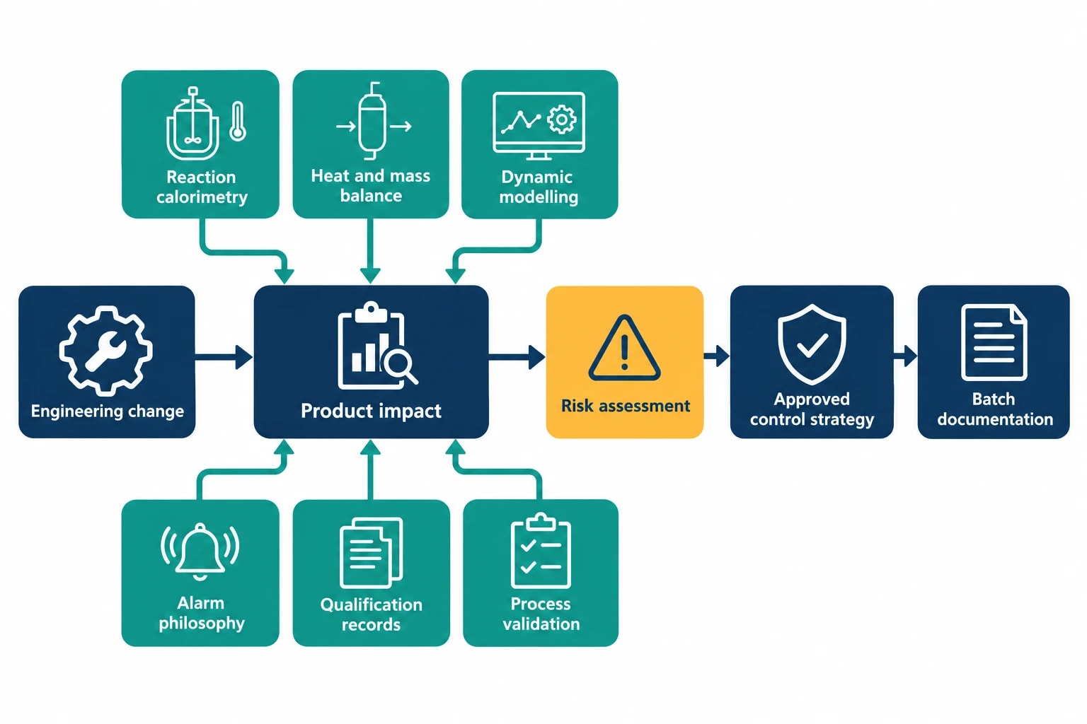
EudraLex Volume 4, Annex 15, Qualification and Validation, has been in operation since 1 October 2015. It establishes a lifecycle approach to qualification and validation and requires documented, risk-based control of changes that could affect product quality.
For exothermic reaction temperature control, a significant change may include:
- A new reactor or a change in reactor scale
- Replacement of a jacket, coil, agitator or temperature probe
- Change of cooling utility, control valve or feed pump
- Revised addition rate, feed temperature or reaction setpoint
- Change in raw-material concentration or impurity profile
- Modified alarm, interlock, trip or emergency operating procedure
- Revised batch-record instructions or acceptance criteria
The change-control assessment should connect the engineering change to the product impact. It should review reaction calorimetry, heat and mass balance, dynamic modelling, alarm philosophy, qualification records, process-validation status and batch documentation. A revised setpoint without this chain of evidence can create a gap between process knowledge and the approved manufacturing control strategy.
ICH Q9(R1) supports this approach. It describes quality risk management as a systematic process for assessing, controlling, communicating and reviewing risks to drug quality across the product lifecycle. Its risk questions apply directly to an exothermic batch operation: what could go wrong, how likely is it, and what would the consequence be for safety and quality?
What the operating team should do after cooling fails
An approved emergency operating procedure should provide the immediate sequence for a cooling failure. The procedure must reflect reaction-specific evidence and site design rather than a generic instruction for any exothermic batch.
The response normally needs to address four priorities:
- Stop further reactant addition and prevent automated restart.
- Confirm agitator status, coolant flow, utility condition and independent temperature indication.
- Apply the approved protective action, such as maximum cooling, quench or controlled transfer, within the demonstrated response time.
- Escalate under the site emergency procedure if temperature, pressure or rate of rise reaches the defined trigger.
After the process is stable, the investigation should preserve the batch trend, alarm sequence, valve positions, feed total, utility data and operator actions. Manufacturing science, process engineering, quality and safety teams need that evidence to determine whether the batch remained within the validated state and whether the control strategy requires change.
Exothermic reaction temperature control needs evidence, not assumptions
The protection strategy should reflect the actual reactor and batch profile rather than an ideal vessel with constant cooling duty and perfect mixing. It should show what happens when cooling capacity falls, agitation stops, feed conditions drift or the reaction behaves at its credible worst case.
This article reflects the independent analysis and editorial opinion of EnerTherm Engineering. Product names, trademarks, and brands mentioned belong to their respective owners. EnerTherm Engineering is not affiliated with, endorsed by, or a licensee of any third-party software or product mentioned unless explicitly stated.

Managing Director — EnerTherm Engineering
Dr. François Pierrel is Managing Director of EnerTherm Engineering with over two decades of expertise in thermal design, heat transfer, and industrial energy optimisation. He holds a PhD in Heat Transfer from Cranfield University and a Post-Doctorate from Heriot-Watt University.
