Heat and Mass Balance for GMP Batch Process Changes
How batch heat loads, solvent recovery and WFI balances inform GMP validation
A heat and mass balance in the pharmaceutical industry is a documented engineering reconciliation of material inputs, outputs, accumulation and thermal duty across a defined process boundary. For GMP batch manufacture, it provides numerical evidence behind changes to reactor capacity, solvent recovery, heating and cooling systems, WFI demand, clean-steam supply and associated control limits.
Solvents typically account for 80 to 90% of the total mass used in API production, according to Raymond, Slater and Savelski’s 2010 Green Chemistry study. That scale means a seemingly local change, such as a revised distillation endpoint or larger reactor charge, can affect utility peaks, waste routes, equipment inventory and validation scope.
A useful balance does more than report energy consumption. It gives engineering, validation and quality teams a common, traceable description of what enters, remains in and leaves the batch process.
Why Heat and Mass Balance Matters in GMP Change Control
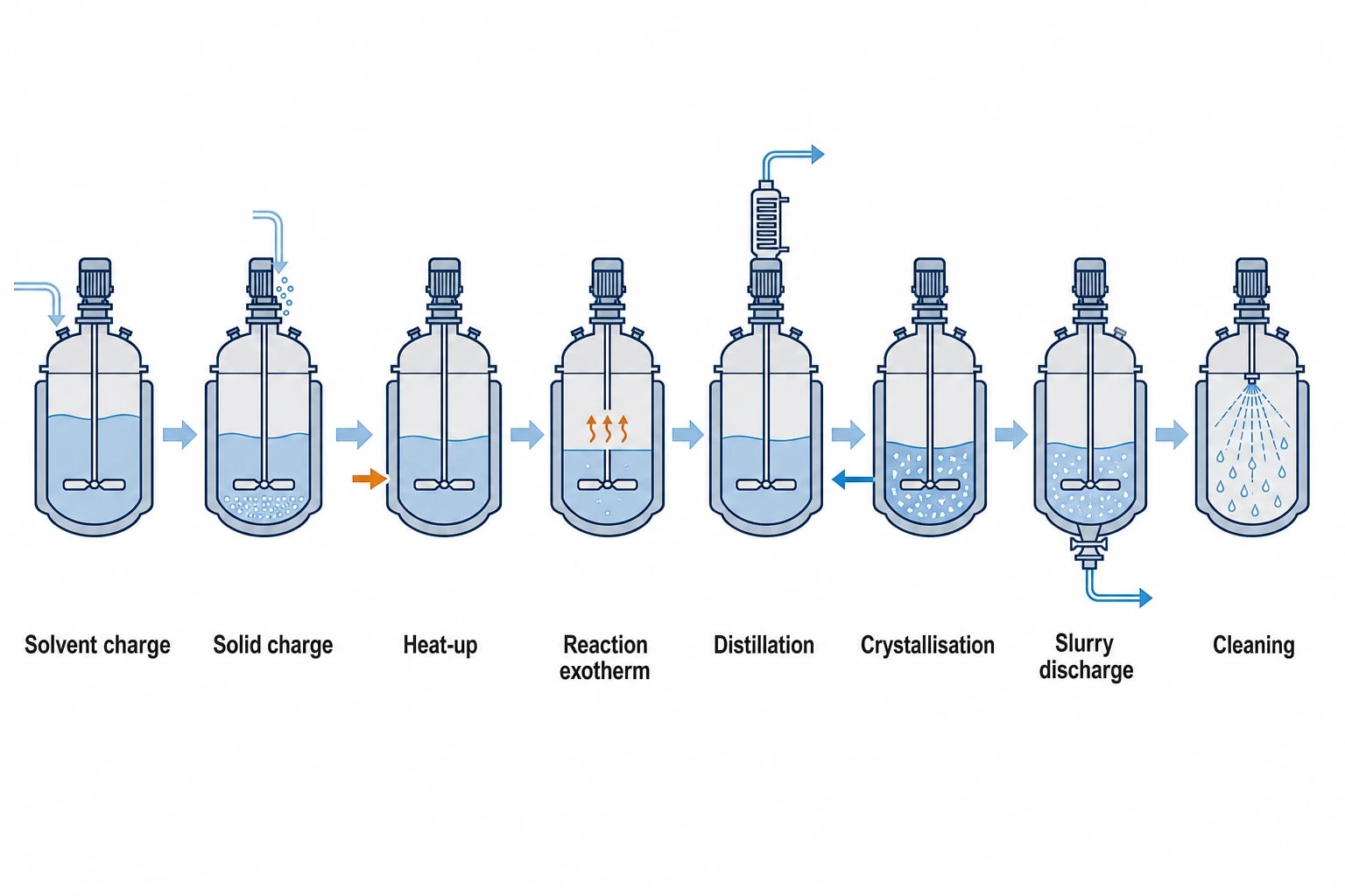
A batch reactor does not operate at one stable condition. It may receive solvent and solid charges, heat through a programmed ramp, control a reaction exotherm, distil volatile material, cool for crystallisation, discharge slurry, then undergo cleaning or sterilisation. Each stage has its own material inventory and heat load.
A daily total for steam or chilled water can conceal the short demand peak that determines whether a shared utility system can maintain the required operating range. Likewise, a yield reconciliation can overstate product recovery if it excludes vessel heel, filter-cake retention, sample withdrawals, condensate inventory or solvent carried into aqueous waste.
Annex 15 links engineering evidence to validation scope
EU GMP EudraLex Volume 4, Annex 15 requires manufacturers to use documented quality risk management to support qualification and validation activities. Significant changes to facilities, systems, equipment or processes need assessment before implementation, with validation scope justified by the potential effect on product quality.
A heat and mass balance provides a technical basis for that assessment. It can show whether a proposed change affects:
- Maximum working volume, agitation performance or vapour space in a reactor.
- Heat-up time, cooling duty or temperature-control capability.
- Solvent composition, condensate quantity and receiver capacity.
- Clean-utility flow, temperature, pressure or coincident demand.
- Hold times, crystallisation conditions, drying behaviour or cleaning performance.
- Material retained in connected equipment and transfer lines.
The document should identify the source of each important value. Batch records, P&IDs, calibrated weigh scales, flow totalisers, laboratory assays, temperature trends and equipment data sheets may each contribute evidence. Where data conflict, the discrepancy needs investigation before the model becomes a controlled basis for change.
The balance should reflect the approved operating range
Design data alone rarely describe plant behaviour during an actual campaign. A reactor jacket may have a stated duty at one utility temperature and flow rate, while the utility network delivers a different condition during concurrent production. A condenser may perform differently when cooling-water return temperatures rise during summer operation.
The analysis should define the intended operating envelope. This normally includes the approved recipe, batch-size range, charge sequence, feed temperatures, agitation conditions, utility supply conditions, relevant vacuum level and expected duration of each phase.

Map every energy and material flow in your process with detailed heat and mass balance calculations — the foundation for any optimisation or design project.
Define the GMP Batch Boundary Before Collecting Data
The process boundary determines whether the balance answers the right question. For a reactor change, the boundary may include the charge vessels, reactor, condenser, receiver, jacket supply and return, vacuum-system interface, vent-treatment connection, discharge route and relevant clean-in-place connections.
For a clean-utility project, the boundary may instead include generation, storage, distribution, return, points of use, sanitisation cycles and drains. Each stream crossing the boundary requires a defined quantity, condition and destination.
Separate product streams from utility streams
Product and utility balances answer different questions, even when they interact.
| Balance area | Information required | GMP change-control question |
|---|---|---|
| Raw-material charging | Mass, assay, composition, sequence and temperature | Does the revised charge remain within approved equipment and recipe limits? |
| Reactor inventory | Heel, reaction mass, solids content, vapour space and retained residue | Does the maximum credible inventory affect pressure, agitation or thermal performance? |
| Vapour and condensate | Condensed solvent, receiver inventory, vent losses and non-condensables | Is the recovery and emissions route still representative? |
| Heating and cooling | Supply and return temperature, flow, pressure and stage timing | Can the utility system meet the required duty at the required time? |
| Cleaning and sterile utilities | WFI, clean steam, rinse volumes, condensate and drain flows | Does the change affect qualified conditions or contamination control? |
A distillation change may leave the product mass balance largely unchanged while increasing condenser duty and cooling-water return temperature. That return temperature can affect other users on a shared network. The H&MB boundary should therefore capture connected systems that could experience a material effect.
Reconcile retained inventory and losses
Batch transitions create many of the hardest reconciliation problems. Material can remain in transfer lines, pump casings, filter housings, condensers, receivers and sampling assemblies. These quantities can be significant for high-potency products, small batches or expensive solvents.
The report should distinguish measured values from estimates. A weighed receiver inventory is measured. A vent loss calculated from vapour-pressure data and estimated condenser efficiency is an estimate. Both may be appropriate if the document identifies the method, assumptions and sensitivity of the result.
This distinction matters in GMP investigations. A model that closes only after unexplained adjustments cannot provide a defensible explanation for a changed yield, utility deviation or waste quantity.
Build a Time-Based Heat Balance for the Batch
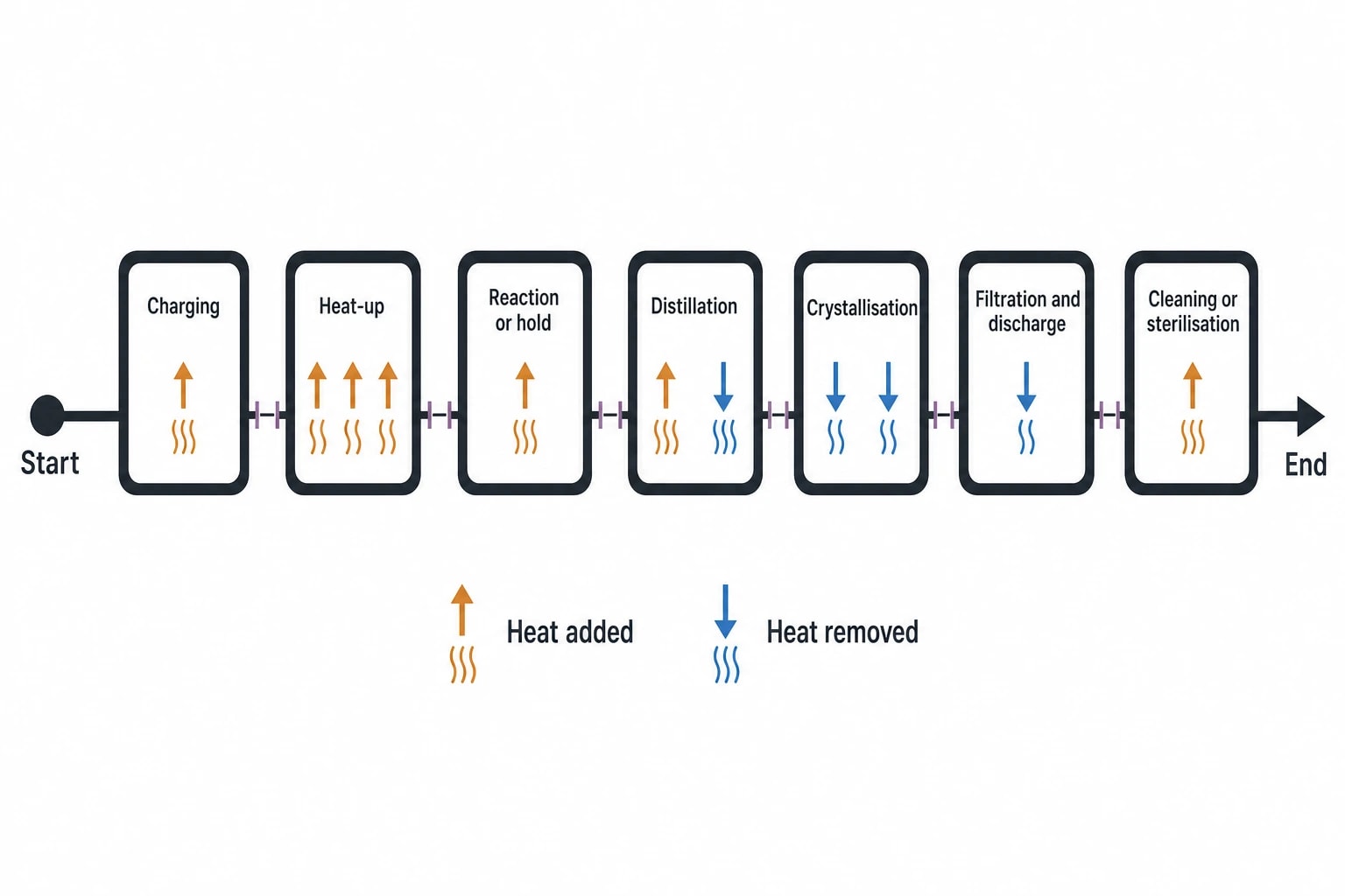
A batch heat balance should show when heat is added or removed, rather than presenting only a total energy figure. Shared steam, hot-water, chilled-water and glycol systems experience coincident loads. Plant capacity depends on the timing and magnitude of those demands.
Divide the recipe into defined thermal stages
The batch record can be converted into stages with a start condition, end condition, mass change and expected duty.
| Batch stage | Principal material event | Main thermal consideration |
|---|---|---|
| Charging | Solids, liquids or solvent enter the reactor | Incoming material temperature and sensible load |
| Heat-up | Inventory remains largely within the reactor | Jacket duty, ramp time and utility peak |
| Reaction or hold | Reaction mass changes, sometimes with gas evolution | Exotherm control and cooling availability |
| Distillation | Vapour leaves and condensate collects | Boil-up duty, condenser duty and vent handling |
| Crystallisation | Solid forms from solution | Cooling rate, mixing and heat of crystallisation |
| Filtration and discharge | Product and mother liquor separate | Wash volumes, retained liquor and residual inventory |
| Cleaning or sterilisation | Water or steam enter and rinses or condensate leave | Peak utility demand and return conditions |
The stages should follow the real operating sequence, including pauses and overlapping activities. Two reactors may each fall within their individual chilled-water allocation yet exceed system capacity when crystallisation stages overlap. Production scheduling belongs in the assessment where shared utility headroom is limited.
Thermal duty and total energy answer different questions
Thermal duty is the rate at which heat must be transferred at a particular time. Total energy is the accumulated heat supplied or removed over a stage. Both are relevant, but they support different decisions.
A long cooling hold can consume substantial energy while demanding little instantaneous cooling capacity. An exothermic feed step may require a much higher peak duty for a short period. That peak determines whether the jacket, control valve, utility supply and temperature-control strategy can maintain the approved range.
For reaction changes, the assessment should consider the planned feed profile, reaction heat where available, batch inventory, solvent concentration, agitation, jacket performance and credible utility supply conditions. A change in feed rate or batch size can move the maximum cooling duty even where final product quantity remains similar.
Assess WFI and Clean Steam as Qualified Utility Systems
Clean utilities require a balance that covers both capacity and quality. The revised EU GMP Annex 1 entered into operation on 25 August 2023, with point 8.123 becoming applicable on 25 August 2024. Its contamination-control expectations make utility changes relevant to sterile-process risk assessment.
WFI balances need demand, return and temperature data
A WFI balance should establish generation rate, storage inventory, distribution flow, points of use, return flow, recirculation temperature, sanitisation demand, flush volumes and drainage. The demand case should include normal production, concurrent cleaning, sampling, recovery after maintenance and credible peak use.
Annex 1 states that WFI storage and distribution systems should minimise microbial growth. Continuous circulation above 70°C is cited as one example of control. An H&MB assessment therefore needs to show whether the changed system can maintain defined circulation and temperature conditions at remote points of use while meeting process demand.
A new branch, altered tank volume or additional user point can change residence time, heat loss, flush requirements and return temperature. Those physical changes should inform qualification, sampling plans and the site contamination-control strategy.
Clean-steam demand includes condensate and peak use
For direct sterilisation applications, clean-steam demand includes warm-up, air removal, the sterilisation hold, distribution losses and condensate production. The balance should identify each user, use pattern, peak coincident demand, condensate route and relevant quality checks.
Annex 1 identifies condensate quality, non-condensable gases, dryness value and superheat as parameters requiring periodic assessment for direct sterilisation uses. A capacity increase, altered steriliser sequence or new steam-in-place branch should therefore enter change control with both a demand profile and a quality-impact assessment.
A generator can have sufficient nominal output while still failing to maintain required conditions during overlapping users. The time-based balance exposes that risk before qualification testing begins.

Map every energy and material flow in your process with detailed heat and mass balance calculations — the foundation for any optimisation or design project.
Use a Species-Level Mass Balance for Solvent Recovery
Solvent recovery needs more detail than a single solvent-in and solvent-out figure. Recovery quality and quantity depend on composition, water content, impurity carry-over, volatile losses, non-condensable gases, material retained in equipment and the approved destination for reclaimed solvent.
Track each solvent destination
The solvent balance should separate the following destinations:
- Recovered solvent that meets its defined reuse or disposal route.
- Recovered solvent requiring further processing, testing or segregation.
- Solvent retained in mother liquor, filter cake, vessel heel or transfer equipment.
- Solvent discharged to aqueous or high-strength waste.
- Solvent directed to controlled vent treatment.
- Solvent contained in samples, cleaning residues or off-specification material.
This approach prevents an apparent increase in recovery from masking a movement of solvent into another waste stream. It also gives environmental, quality and waste-management records a common material basis.
Test condenser and vacuum changes against the operating envelope
A revised distillation endpoint, changed vacuum level, larger condenser or altered cooling-medium temperature can affect recovery yield and vent loading. The model should compare the previous and proposed process on the same batch basis, then test credible high and low operating conditions.
Reclaimed solvent should appear as a defined material stream with composition, quantity and destination. Reuse may require specification, testing and approval under the pharmaceutical quality system. The H&MB provides engineering evidence for those decisions, while the quality system determines the route to use.
Convert the H&MB into a Validation-Ready Change Package
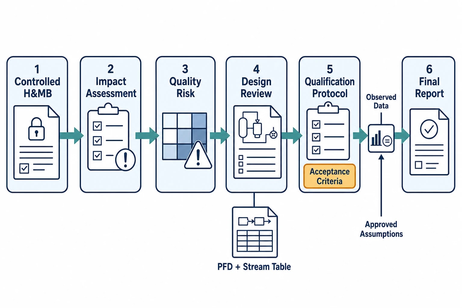
A strong GMP package traces the proposed change from engineering calculation through testing and final approval. Annex 15 expects validation protocols to identify critical systems, attributes, parameters and acceptance criteria. The H&MB helps select those items on a justified basis.
Turn calculated loads into testable acceptance criteria
The assessment should identify directly changed systems and connected systems that may be affected. A reactor-jacket modification may affect the reactor, utility loop, control configuration, alarms, pressure protection, batch recipe and cleaning cycle. A WFI branch extension may affect loop circulation, temperature maintenance, sanitisation and sampling.
| Change-package item | Contribution from the H&MB |
|---|---|
| Change-control impact assessment | Defines material, thermal and utility consequences |
| Quality risk assessment | Identifies where altered conditions could affect product quality or system performance |
| Design review | States required capacities, temperatures, flows and batch ranges |
| Qualification protocol | Converts duties and operating limits into measurable acceptance criteria |
| Process validation assessment | Assesses whether the revised process remains within the approved control strategy |
| Updated PFD and stream table | Creates a controlled record of streams, duties and interfaces |
| Final report | Compares observed qualification data with approved assumptions |
Acceptance criteria should be set before testing. Relevant examples include a defined reactor temperature profile, maximum receiver inventory, minimum WFI return temperature, clean-steam capacity during a specified sterilisation sequence, or cooling performance under an approved worst-case scenario.
Compare qualification results with the approved balance
The post-change report should compare actual batch masses, utility flows, temperatures, durations and recovery quantities with the approved model. A discrepancy requires explanation and impact assessment.
The cause may be a different production schedule, feed-temperature variation, metering error, unaccounted vessel heel or an inaccurate engineering assumption. The investigation should establish whether the variance affects validated conditions, product quality, utility capability or ongoing operating limits.
This comparison improves the model for future changes. A controlled H&MB can provide a reliable reference for later capacity studies, deviation investigations and planned maintenance work.
Keep Energy Recovery Within GMP Process Boundaries
The UK Government’s study of eight heat-intensive sectors identified 48 TWh per year of industrial waste-heat sources, including 8 TWh per year of economic recovery potential. That finding supports a disciplined review of heat recovery where a pharmaceutical site has suitable temperature levels and a stable demand sink.
For GMP batch operations, a heat-recovery proposal should begin with the established H&MB. The assessment should show the source temperature profile, heat quantity, batch timing, receiver demand and any effect on segregation, cleanability, utility quality or contamination control.
A reactor condenser may offer a recoverable heat source during distillation, but the project must preserve process control and prevent unacceptable utility interfaces. The H&MB gives the site a numerical basis for energy reduction, solvent-recovery decisions and capital investment while maintaining validation evidence for the batch process.
This article reflects the independent analysis and editorial opinion of EnerTherm Engineering. Product names, trademarks, and brands mentioned belong to their respective owners. EnerTherm Engineering is not affiliated with, endorsed by, or a licensee of any third-party software or product mentioned unless explicitly stated.

Managing Director — EnerTherm Engineering
Dr. François Pierrel is Managing Director of EnerTherm Engineering with over two decades of expertise in thermal design, heat transfer, and industrial energy optimisation. He holds a PhD in Heat Transfer from Cranfield University and a Post-Doctorate from Heriot-Watt University.
