Flow Chemistry Heat Transfer Design at up to 10,000 m²/m³
How to characterise the three partial thermal resistances using the Wilson Plot method.
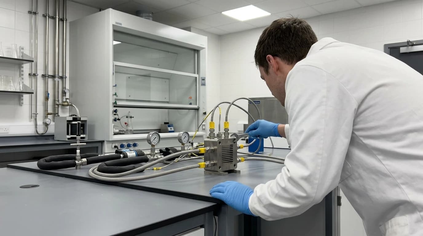
Flow chemistry heat transfer design is a thermal engineering methodology focussed on configuring and optimising continuous-flow reactor systems to manage heat transport across exceptionally high surface-area-to-volume ratios of up to 10,000 m²/m³. Traditional batch processing relies on jacketed vessels with minimal heat transfer area relative to the reaction mass. In contrast, continuous-flow systems utilise narrow channels, structured internals, and advanced materials to achieve precise temperature control. This design approach is essential for scaling up highly exothermic, fast chemical processes in the pharmaceutical and speciality chemical sectors, ensuring reactions run under near-isothermal conditions to maintain safety, selectivity, and product purity.
What is Flow Chemistry Heat Transfer Design?
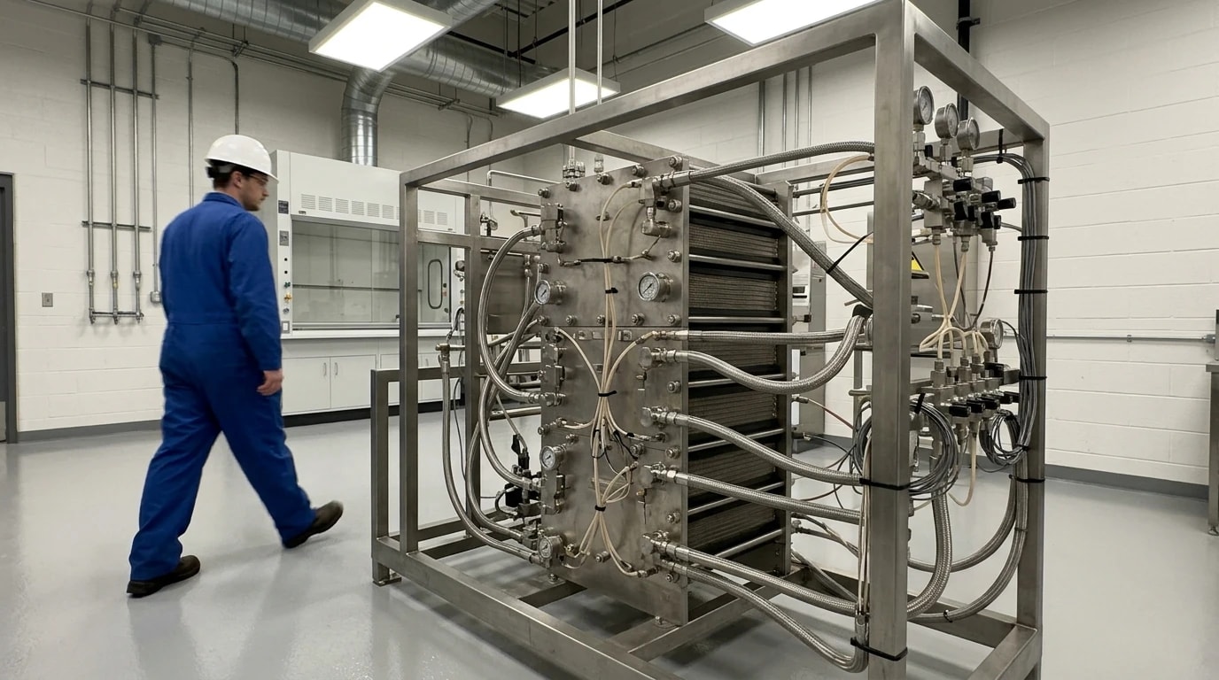
Standard industrial batch vessels exceeding 1,000 litres typically possess a surface-area-to-volume ratio (A/V) of only 2 to 5 m²/m³. When a highly exothermic reaction—such as a nitration, organometallic coupling, or halogenation—is executed at this scale, this limited surface area cannot remove thermal energy as fast as reaction kinetics generate it. To prevent hazardous thermal runaway, manufacturers must operate under semi-batch, feed-controlled conditions, adding reagents slowly over several hours. This operational constraint artificially extends cycle times and limits throughput.
Flow chemistry heat transfer design resolves this bottleneck by transitioning the process from a bulk vessel to continuous-flow channels. In these systems, fluid passes through micro- or meso-scale channels with characteristic dimensions measured in millimetres or micrometres. This physical downsizing increases the specific surface area dramatically. A typical micro-reactor achieves a surface-area-to-volume ratio between 2,000 and 2,500 m²/m³, while highly engineered structures like heterogeneous micro-packed beds or foam-filled channels can reach up to 10,000 m²/m³.
This geometric advantage allows heat transfer rates to match rapid chemical kinetics. Consequently, reactions requiring hours of controlled cooling in batch vessels can run safely in seconds or milliseconds under continuous conditions, maintaining a virtually constant temperature along the flow path.

Map every energy and material flow in your process with detailed heat and mass balance calculations — the foundation for any optimisation or design project.
Characterising Thermal Resistance in Continuous Microreactors
Designing continuous systems requires calculating the overall heat transfer coefficient (U). This parameter governs the rate of heat transfer from the process stream, through the channel wall, and into the utility fluid. The overall thermal resistance is modelled as a series network of three partial resistances:
U1=hr1+λdw+hj1where:
- U is the overall heat transfer coefficient (W/m²K).
- hr is the convective film heat transfer coefficient on the process side (W/m²K).
- dw is the thickness of the reactor partition wall (metres).
- λ is the thermal conductivity of the wall material (W/m·K).
- hj is the convective film heat transfer coefficient on the utility side (W/m²K).
Reactor-Side Film Resistance
The process fluid film coefficient (hr) depends heavily on the flow regime and channel geometry. In standard micro-channels, flow is almost exclusively laminar because of low Reynolds numbers. In smooth channels under laminar conditions, heat transfer is low because a static boundary layer forms along the wall, acting as an insulating barrier. Overcoming this resistance requires channel configurations that periodically disrupt this boundary layer, bringing fresh bulk fluid to the wall surface.
Reactor Wall Conduction Resistance
The wall conduction resistance (dw/λ) represents the conductive barrier of the solid partition separating the process and utility fluids. Material selection is critical. Borosilicate glass is popular in laboratories for its transparency and chemical compatibility, but its low thermal conductivity (λ≈1.1 W/m·K) imposes a major bottleneck during scale-up. For industrial production, designers specify silicon carbide (λ≥100 W/m·K) or specialised metal alloys like Hastelloy or tantalum to minimise this resistance.
Utility-Side Film Resistance
The utility-side convective film heat transfer coefficient (hj) is governed by jacket or cooling-channel design. To prevent the utility side from limiting overall performance, designers ensure utility fluids flow at high velocities. Operating under turbulent regimes (Reynolds numbers exceeding 4,000) minimises the convective resistance (1/hj).
The Wilson Plot Method for Parameter Isolation
Isolating these three resistances experimentally is challenging during process development; sensors cannot easily measure local interfacial temperatures inside sub-millimetre channels. Engineering teams overcome this by utilising the Wilson Plot method.
By operating the flow system at a constant process flow rate while systematically varying the utility fluid velocity, engineers plot the reciprocal of the measured overall heat transfer coefficient ($1/U$) against the reciprocal of the utility fluid velocity raised to an empirical power. The resulting straight line has a vertical intercept representing the sum of the wall conduction resistance (dw/λ) and the process-side film resistance (1/hr). This technique isolates the individual film coefficients with high precision, providing the empirical foundation needed to validate process simulations.
Fluid Dynamics and Passive Mixing Geometries
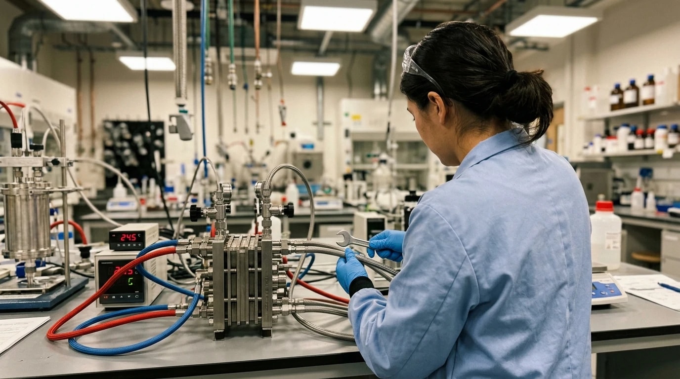
A primary challenge in flow thermal design is balancing the process-side convective coefficient (hr) against the hydraulic pressure drop (ΔP) across the reactor.
The Pressure Drop Penalty in Microscale Channels
To increase the convective film coefficient in a smooth tube, engineers must either increase fluid velocity or reduce channel diameter. However, reducing the hydraulic diameter (dh) causes the frictional pressure drop to rise exponentially. In laminar flow, the pressure drop in a tube increases inversely with the fourth power of the diameter.
An excessive pressure drop restricts the maximum reactor length, risks mechanical seal failure, and demands expensive high-pressure dosing pumps. Simply extending micro-channel lengths is therefore rarely a viable scale-up strategy.
Boundary Layer Disruption via Passive Mixing
Rather than relying on high velocities in narrow capillaries, advanced thermal design incorporates passive mixing structures within the fluidic modules. These configurations alter the flow path to generate chaotic advection and secondary flows, even in low-velocity laminar regimes.
These passive geometries split, rotate, and recombine process streams continuously. This mechanical action forces bulk fluid from the centre of the channel to the wall. Disrupting the thermal boundary layer in this way maintains a high process-side heat transfer coefficient (hr) without the massive pressure drop penalty of straight capillaries.
Industrial Scale-Up: Technologies for Preserving Heat Transfer
Transitioning an optimised flow process from laboratory scale to industrial manufacture requires reactor designs that preserve mass and heat transfer coefficients at higher flow rates. Engineers avoid simply expanding channel diameters, as this rapidly decreases the surface-area-to-volume ratio and reverts the system to heat-transfer-limited behaviour.
Structured Plate Reactors
Many industrial lines utilise plate-based reactors, such as the Corning Advanced-Flow Reactors (AFR) G4 system, to achieve high throughput. Instead of standard cylindrical tubes, these reactors employ thin, micro-structured fluidic modules sandwiched between dedicated utility heat-exchange layers.
Typically fabricated from ceramic silicon carbide (SiC), these modules combine excellent thermal conductivity with robust chemical resistance. The internal channels utilise patented heart-shaped or split-recombine structures to induce continuous high-shear mixing. This plate architecture maintains volumetric heat transfer coefficients between 1.0 and 1.6 MW/m³K. It enables seamless scale-up from laboratory to production scale by maintaining identical channel geometries and increasing the number of parallel channels or plates.
Active Mixing via Oscillatory Flow Baffled Reactors
For reactions requiring long residence times (ranging from minutes to hours) or involving heterogeneous slurries, passive micro-channels are prone to fouling, sedimentation, and excessive pressure drops. Here, process development teams often select continuous oscillatory flow baffled reactors (OFBRs).
An OFBR consists of a tubular column containing periodically spaced orifice-plate baffles. An external diaphragm or piston overlays a reciprocating fluid oscillation onto the net forward flow of the process stream. This oscillatory motion interacts with the sharp edges of the baffles to generate uniform, high-shear vortices that continuously sweep the reactor walls.
This mechanism decouples mixing from the net flow rate. Process engineers can achieve long residence times and low net velocities while maintaining high convective coefficients (hr) and preventing solid settling, all without incurring the high pressure drops typical of micro-channel networks.

Map every energy and material flow in your process with detailed heat and mass balance calculations — the foundation for any optimisation or design project.
Regulatory Compliance, PAT Integration, and GMP Validation
In the pharmaceutical and speciality chemical sectors, flow thermal design must comply with strict Good Manufacturing Practice (GMP) regulations and international guidelines, such as the ICH Q13 guideline (2022) for the continuous manufacturing of drug substances and drug products.
Thermal Control as a Critical Process Parameter
Under the Quality by Design (QbD) framework, reaction temperature is frequently classified as a Critical Process Parameter (CPP). It directly impacts impurity formation and the Critical Quality Attributes (CQAs) of the Active Pharmaceutical Ingredient (API). The superior heat transfer of flow reactors enables tight isothermal control. Rapid heat dissipation prevents local hot spots, which in batch reactors often cause thermal degradation, decreased selectivity, and safety hazards.
Integration of Process Analytical Technology
Continuous-flow systems facilitate direct integration of Process Analytical Technology (PAT) tools into the fluidic modules. In-line sensors, such as multi-point thermocouple arrays, infrared spectrometers, and pressure transducers, continuously monitor the reaction state.
Because the thermal response time of a micro-structured reactor is measured in milliseconds, real-time temperature data can couple directly with dynamic control loops. If a process deviation occurs, local automated systems like the temperature control unit (TCU) can instantly adjust the utility fluid temperature or flow rate. This maintains the reaction path within its validated state while the monitoring platform informs operators of real-time quality metrics.
Quantitative Comparison of Reactor Thermal Configurations
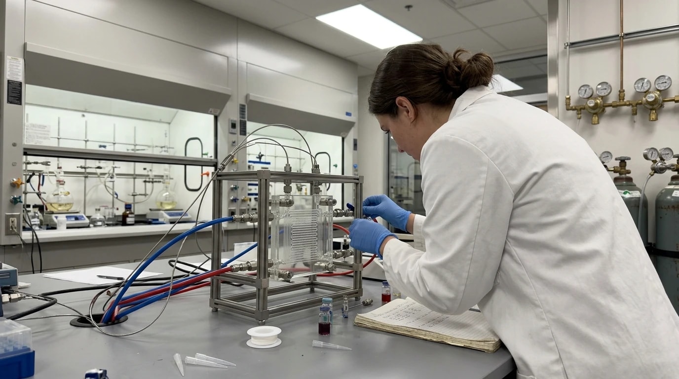
The following table summarises the physical, hydrodynamic, and thermal performance characteristics of key reactor designs, illustrating the capabilities of high-surface-area continuous architectures.
| Reactor Configuration | Typical Surface-to-Volume Ratio (m²/m³) | Convective Heat Transfer Coefficient (W/m2K) | Volumetric Heat Transfer Coefficient (MW/m3K) | Primary Operational Constraints & Characteristics |
|---|---|---|---|---|
| Industrial Jacketed Batch Vessel (1,000+ L) | 2 – 5 | 50 – 300 | 0.001 – 0.005 | Severe heat-removal limits; long feed times required to manage exothermic reactions. |
| Standard Smooth Capillary Flow Reactor | 1,000 – 4,000 | 500 – 2,000 | 0.1 – 0.5 | High pressure drop at high flow velocities; rapid thermal boundary layer growth limits heat transfer downstream. |
| Structured Plate Reactor (e.g., Corning AFR G4) | 2,000 – 2,500 | 3,000 – 7,000 | 1.0 – 1.6 | High initial capital expenditure; limited tolerance for highly heterogeneous mixtures or large solids. |
| Oscillatory Flow Baffled Reactor (OFBR) | 100 – 500 | 500 – 1,500 | 0.05 – 0.2 | Mechanical complexity of the fluid oscillation drive; larger physical footprint than micro-plate reactors. |
| Heterogeneous Foam or Packed-Bed Microreactor | 5,000 – 10,000 | 4,000 – 8,000 | 2.0 – 5.0 | Extreme pressure drop; high risk of channel blockage; challenging catalyst packing validation for GMP use. |
Designing for Future Manufacturing Demands
Implementing an effective flow chemistry heat transfer design is a key requirement for process development teams transitioning pharmaceutical synthesis from batch to continuous manufacturing. By managing the three partial thermal resistances, utilising boundary layer disruption, and specifying materials with high thermal conductivity, engineers can establish near-isothermal reaction conditions. This precise control reduces footprint requirements, mitigates chemical hazards, and ensures a reproducible, GMP-compliant process that meets the strict regulatory expectations of modern chemical manufacturing.
This article reflects the independent analysis and editorial opinion of EnerTherm Engineering. Product names, trademarks, and brands mentioned belong to their respective owners. EnerTherm Engineering is not affiliated with, endorsed by, or a licensee of any third-party software or product mentioned unless explicitly stated.

Managing Director — EnerTherm Engineering
Dr. François Pierrel is Managing Director of EnerTherm Engineering with over two decades of expertise in thermal design, heat transfer, and industrial energy optimisation. He holds a PhD in Heat Transfer from Cranfield University and a Post-Doctorate from Heriot-Watt University.
