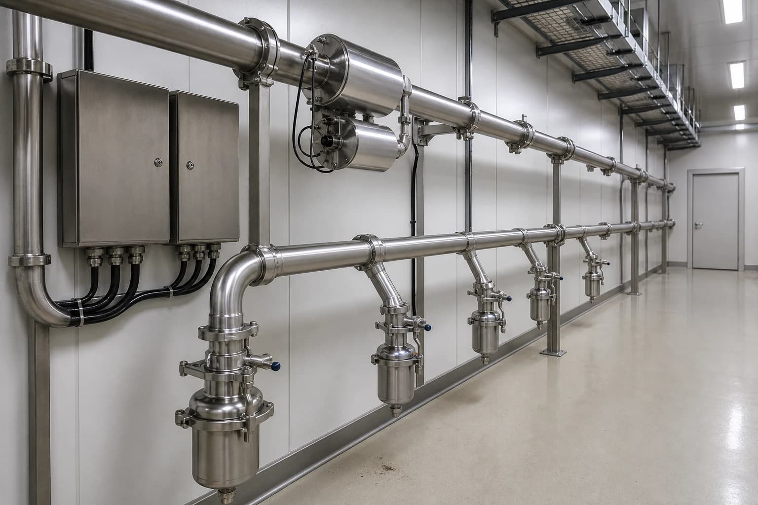
Pharmaceutical Utility System Design After Annex 1
Annex 1 sections 6.7-6.17 set design controls for WFI, purified water and clean steam.
Since 25 August 2024, every provision of the revised EU GMP EudraLex Volume 4 Annex 1 has applied, placing pharmaceutical utility system design within the contamination-control case for sterile manufacture.
Water for Injections, purified water, clean steam and HVAC support production equipment, but their impact extends to microbial, endotoxin, particulate and pyrogen control. Annex 1 expects manufacturers to show how each utility was designed, qualified, monitored and maintained throughout its operating life. A datasheet showing capacity and pressure does not provide that assurance.
For new facilities and upgrades, the design package must connect process demand to contamination risk. That connection starts with the Contamination Control Strategy, then runs through heat and mass balances, user requirements, piping and instrumentation diagrams, commissioning records and the monitoring plan.
Annex 1 makes the Contamination Control Strategy the design brief
Annex 1 requires a facility-wide Contamination Control Strategy, or CCS, that defines critical control points and assesses the combined effectiveness of design, procedural, technical and organisational controls. Utilities are explicitly among the elements to consider.
The CCS should inform the utility user requirement specification before equipment selection. Retrofitting a rationale after a WFI loop, clean-steam generator or air-handling unit has been purchased can expose expensive constraints in layout, drainage, access and instrumentation.
Map utility contamination pathways to physical controls
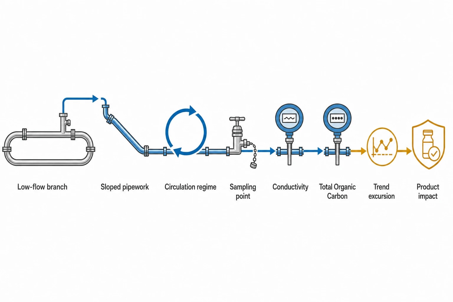
The utility design team should identify how contamination could reach product, product-contact surfaces or the critical zone. Relevant pathways include microbial growth in low-flow water branches, endotoxin in WFI or clean-steam condensate, particles from poor air control, chemical carryover from steam generation, and pressure reversals between cleanroom grades.
Each pathway needs a defined design response. Examples include:
- Sloped, drainable water pipework and short sanitary branches.
- A qualified circulation regime, sanitisation strategy and representative sampling points.
- Continuous WFI conductivity and total organic carbon monitoring at risk-based locations.
- Purified feedwater and condensate sampling for clean steam.
- Pressure-differential monitoring and airflow visualisation for cleanrooms.
The CCS should identify the evidence that proves each control works. A pressure alarm, WFI trend excursion or failed post-maintenance test can then be assessed against a documented product-impact pathway.
Define intended use at each point of use
A label such as “clean utility” is insufficient for pharmaceutical utility system design. The user requirement must state whether the utility contacts product, contacts a sterilised product-contact surface, supports cleaning, provides a sterilising medium, or controls the manufacturing environment.
That classification determines the design and qualification burden. WFI for formulation or a final rinse has different quality and availability requirements from purified water used for an intermediate wash. Plant steam serving a non-product heating jacket requires a different control strategy from clean steam used to sterilise porous hard goods.
A point-of-use register should identify utility, quality attribute, operating range, demand profile, connection type, cleaning or sterilisation requirement, and sampling requirement. It should be reconciled against the process flow diagram before detailed pipe routing begins.

Map every energy and material flow in your process with detailed heat and mass balance calculations — the foundation for any optimisation or design project.
Build heat and mass balances around real operating conditions
A pharmaceutical utility system design needs a time-based heat and mass balance, not a daily consumption estimate. Batch production creates concurrent peaks that can exceed average demand by a wide margin.
A single shift may combine vessel cleaning, sterilise-in-place cycles, autoclave use, formulation, filling support and final rinsing. Each duty can draw WFI, purified water, clean steam, chilled water, heating water or conditioned air simultaneously.
Size for simultaneous demand, recovery and loss of a train
The design basis should separate several operating cases:
- Maximum simultaneous demand during the production schedule.
- Normal batch demand.
- Minimum recirculation demand for water distribution loops.
- Start-up and recovery after sanitisation, shutdown or maintenance.
- Demand during an unavailable generation or distribution train.
- Credible future expansion with a defined project basis.
A WFI system can meet its daily volume target yet fail the production schedule if a short demand peak depletes storage and reduces circulation at remote users. A clean-steam generator can satisfy nominal evaporation duty while an autoclave sequence creates an unplanned pressure or quality constraint. The utility profile must model time, not only total consumption.
Include reject, return and standing-load duties
The water balance should follow incoming water through pretreatment, reverse-osmosis reject where used, electrodeionisation reject where applicable, storage, sanitisation discharge, distribution, sampling and final disposal. These flows affect water-treatment capacity, drainage and operating cost.
The heat balance should include generation duty, tank and distribution heat loss, hot-loop circulation, clean-steam generation, steriliser demand, condensate handling and HVAC coil loads. A temperature-maintained WFI loop has a continuous thermal duty even during low production demand. The operating model should include that duty rather than treating it as an incidental loss.
A controlled process flow diagram with stream tables provides a practical common record. For each utility stream, record normal and peak flow, pressure, temperature, quality, return or drain route, and point-of-use function.
| Utility | Heat and mass balance focus | Design evidence required |
|---|---|---|
| Purified water | Generation yield, storage turnover, sanitisation discharge and distribution demand | Chemical and microbial control across operating states |
| WFI | Generation rate, recirculation duty, storage, user demand and sanitisation losses | Hydraulic, thermal and sampling evidence at worst-case locations |
| Clean steam | Purified feedwater, evaporation, blowdown, condensate and steriliser load | Condensate quality at representative use conditions |
| HVAC | Outdoor-air load, room heat release, pressurisation and recovery | Airflow and pressure relationships that protect the critical zone |
WFI and purified-water distribution require a qualified hydraulic basis
Annex 1 sections 6.7 to 6.15 require water treatment and distribution systems to prevent microbiological contamination and provide water of appropriate quality. The requirement covers design, construction, installation, commissioning, qualification, monitoring and maintenance.
Generation quality alone cannot secure the distribution system. The loop, branches, valves, instruments, sample points and return must preserve control to the point of use.
Turn “turbulent flow” into a design criterion
Annex 1 section 6.9 requires turbulent water flow through distribution pipework to reduce microbial adhesion and biofilm formation. It also requires the flow rate to be established during qualification and routinely monitored. The Annex does not prescribe a universal velocity because pipe diameter, water temperature, system geometry and operating mode differ between systems.
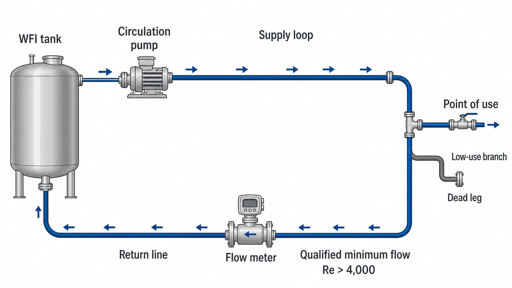
The user requirement should specify a qualified minimum recirculation condition. A common engineering criterion is a Reynolds number above 4,000 in continuously circulating pipework, calculated using the actual internal diameter, water properties at the lowest operating temperature, and the minimum credible recirculation flow. That calculation should cover the return leg and every continuously swept section, rather than relying on a pump nameplate or nominal line velocity.
Velocity remains useful, but cannot stand alone. A velocity that produces turbulent flow in a small branch may give a different Reynolds number in a larger main. The design review should confirm:
- The pump can sustain the qualified minimum flow at the expected system resistance.
- Control valves and normal operating positions do not reduce circulation below the qualified condition.
- The return line provides a reliable measurement point for ongoing verification.
- Pipework remains fully flooded in its intended operating mode.
- Low-use branches do not become stagnant zones between the loop and the user connection.
A branch beyond the circulating path needs separate control through geometry, drainability, defined use, flushing or sanitisation. A Reynolds-number calculation for the main loop does not establish turbulent flow inside an isolated dead leg.
Design drainage, branches and samples as one system
Annex 1 identifies complete drainage and avoidance of dead legs as risk-reduction measures. The review should examine valve clusters, instrument tees, sample valves, filter housings, hoses and little-used outlets as closely as the main ring main.
The distribution layout should include a slope strategy, drain points, sanitary valve arrangements and access for inspection and maintenance. The commissioning package should prove that intended drain paths work in the installed system, including elevation changes that are easy to miss on a two-dimensional drawing.
Sampling must be representative rather than merely convenient. Annex 1 requires programmes to include outlets and points of use at specified intervals, based on qualification data and potential worst-case locations. At least one representative sample of water used for manufacturing must be included daily. Typical worst cases include the tank outlet, return line, coolest point, most distant outlet and least-used branch.
Select WFI generation technology on sustained control
Annex 1 permits WFI production by distillation or a purification process equivalent to distillation. It gives reverse osmosis coupled with appropriate techniques, including electrodeionisation, ultrafiltration or nanofiltration, as examples.
The technology decision should follow a documented assessment of feedwater variability, required availability, pretreatment, sanitisation, maintenance access, reject handling, storage conditions and point-of-use demand. The selected route must consistently produce water quality that the manufacturer can sustain and qualify.
For WFI storage and distribution, Annex 1 cites constant circulation above 70 °C as an example of a measure that minimises microbial growth. Where a tank has a hydrophobic bacteria-retentive vent filter, the design must prevent condensate forming on the filter and provide for integrity testing before installation and after use.
European Pharmacopoeia changes require controlled specification updates
The European Pharmacopoeia Commission adopted revised texts for Water for Injections monograph 0169, Purified Water monograph 0008 and Total Organic Carbon in Water for Pharmaceutical Use chapter 2.2.44 in June 2025. They entered into force in European Pharmacopoeia Issue 12.3 on 1 July 2026.
For WFI in bulk, the revised monograph specifies a TOC limit of 0.50 mg/L. The revision also replaced the oxidisable-substances test with TOC for Sterilised Water for Injections. Specification documents, laboratory methods, data systems and qualification protocols should reflect the applicable pharmacopoeial text.
Manage the recombinant factor C transition accurately
European Pharmacopoeia Issue 13.1 is available, but its new and revised texts become applicable on 1 January 2027. That timing matters for endotoxin-method control.
Until that date, the water monographs allow bacterial endotoxin testing under European Pharmacopoeia chapter 2.6.14 or the standalone recombinant-factor-C chapter 2.6.32. WFI carries a bacterial endotoxin limit of less than 0.25 IU/mL.
From 1 January 2027, Issue 13.1 incorporates recombinant factor C as method G in chapter 2.6.14 and suppresses chapter 2.6.32 as obsolete. Water-monograph references must therefore be updated through formal change control. Sites should assess the analytical method, procedural references, training, electronic templates and validation records before the implementation date.
Continuous WFI TOC and conductivity monitoring remains an Annex 1 expectation, with sensor locations selected through risk assessment. These measurements provide timely evidence of overall system performance. They do not replace the chemical, microbial and endotoxin sampling defined by the qualified monitoring programme.

Map every energy and material flow in your process with detailed heat and mass balance calculations — the foundation for any optimisation or design project.
Clean-steam design must prove condensate quality at use
Annex 1 sections 6.16 and 6.17 treat direct sterilising steam as a high-risk utility. The relevant question is the quality of representative condensate at the steriliser or product-contact use condition.
Separate plant steam from clean steam
Plant steam may serve non-product heating duties where site controls permit. Direct sterilisation requires a separately controlled clean-steam supply because conventional boiler additives or contaminants may introduce unacceptable risk to product-contact surfaces or sterilised materials.
Annex 1 requires appropriately purified feedwater for a clean-steam generator. The generator must be designed, qualified and operated to achieve defined chemical and endotoxin levels. Feedwater source, storage, pretreatment, generator operating range and steam distribution form one qualification boundary.
Qualify against realistic loads and routes
For direct sterilisation of materials or product-contact surfaces, Annex 1 requires clean-steam condensate to meet the current WFI monograph of the relevant pharmacopoeia. Routine microbial testing of condensate is not mandatory, but the sampling schedule must produce representative steam for regular analysis.
Qualification should include the actual steriliser load, line warm-up, condensate removal, pressure reduction where fitted, and the longest or most difficult distribution route. A sample at the generator outlet cannot demonstrate quality at every steriliser.
Annex 1 also requires periodic assessment of non-condensable gases, dryness fraction and superheat against validated parameters, unless justified otherwise. These attributes affect steam behaviour during sterilisation and belong in the clean-steam qualification plan.
HVAC completes the utility contamination-control case
HVAC design must support cleanroom classification, process conditions and the CCS. Equipment heat release, steam use, autoclave doors, transfer routes and operator interventions can affect airflow patterns where sterile product is exposed.
Apply ISO 14644 alongside Annex 1
ISO 14644-1:2015 defines classification of air cleanliness by airborne particle concentration. ISO 14644-2:2015 addresses monitoring evidence for particle-cleanliness performance. ISO 14644-3:2019 provides cleanroom test methods.
These standards support the HVAC qualification programme, but Annex 1 requires a pharmaceutical assessment of viable, particulate and process-contamination risks. Particle classification alone does not establish control of microbial contamination or endotoxin risk.
Prove pressure and airflow at rest and in operation
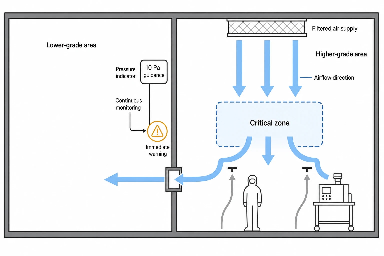
Annex 1 gives 10 Pa as the guidance value for pressure difference between adjacent rooms of different grades. Containment requirements for potent, pathogenic or live biological materials may require a different arrangement. The CCS must document the rationale and show how the design protects the critical zone.
Critical pressure differentials require continuous monitoring, recording and an immediate warning system. Alarm delays need documented CCS justification. Engineering, production and quality teams should agree excursion responses before operational qualification.
Annex 1 also requires airflow visualisation studies at rest and in operation. The studies must demonstrate that lower-grade air does not enter higher-grade areas and that air does not pass from floors, operators or equipment towards the critical zone. HVAC and utility layouts should be reviewed together before construction fixes access panels, pipe routes and heat sources in place.
Qualification evidence should follow the design logic
A compliant pharmaceutical utility system design creates a traceable evidence chain from product need to routine control. The principal records should connect the CCS, user requirements, risk assessments, heat and mass balance, process flow diagrams, piping and instrumentation diagrams, material specifications, operating ranges, sampling plans and maintenance procedures.
Each design change needs an impact assessment against that chain. A new WFI point of use can alter loop turnover and peak demand. A clean-steam user can change generator loading and condensate conditions. A new autoclave or process skid can alter HVAC heat load and airflow behaviour. The change-control record should show whether the qualified state remains valid or whether requalification is required.
Maintainability belongs in the original design. Accessible instruments, controlled isolation points, drainable pipework, sanitisation connections, post-maintenance flushing and return-to-use testing reduce the chance that corrective work becomes a contamination event.
This article reflects the independent analysis and editorial opinion of EnerTherm Engineering. Product names, trademarks, and brands mentioned belong to their respective owners. EnerTherm Engineering is not affiliated with, endorsed by, or a licensee of any third-party software or product mentioned unless explicitly stated.

Managing Director — EnerTherm Engineering
Dr. François Pierrel is Managing Director of EnerTherm Engineering with over two decades of expertise in thermal design, heat transfer, and industrial energy optimisation. He holds a PhD in Heat Transfer from Cranfield University and a Post-Doctorate from Heriot-Watt University.
