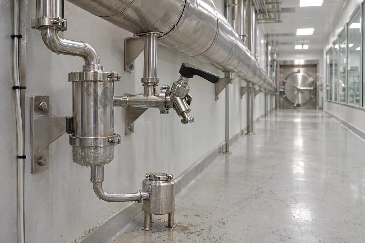
Clean Steam System Optimisation Under EU GMP Annex 1
How EN 285 tests dryness, superheat and non-condensable gases
Clean steam system optimisation reduces clean-steam energy use and capacity losses while preserving validated steam quality, sterilisation performance and contamination controls in pharmaceutical manufacture.
A pure steam generator can consume substantial thermal energy while supplying intermittent autoclaves, steam-in-place circuits and component sterilisers. The cost extends beyond generation. Heat loss through distribution pipework creates condensate, poor drainage can reduce delivered steam quality, and coincident demand can make a generator appear capacity-constrained.
EU GMP Annex 1 sets a hard boundary around any optimisation programme. The revised Annex became applicable on 25 August 2023; only paragraph 8.123 had deferred applicability until 25 August 2024. A lower utility load does not prove that a modification is acceptable. The site must show that the altered system continues to supply suitable steam at the point of use under routine and worst-case operating conditions.
What EU GMP Annex 1 requires from clean steam systems
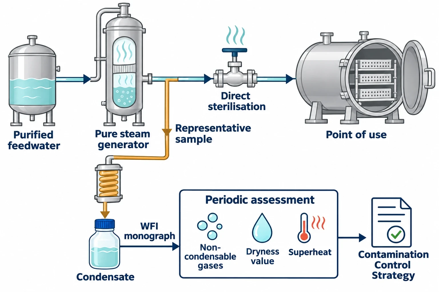
Annex 1 treats steam used for sterilisation as a higher-risk utility where it directly contacts product, product-contact surfaces or materials that will become part of the product. Controls must be proportionate to the product-quality risk and recorded in the Contamination Control Strategy.
The exact requirements for pure steam
Annex 1 paragraph 6.16 addresses the generator and its feedwater. It requires feedwater to a pure-steam or clean-steam generator to be appropriately purified. The generator must be designed, qualified and operated so that the steam produced meets defined chemical and endotoxin levels.
Paragraph 6.17 addresses steam used as a direct sterilising agent. It requires suitable steam quality and prohibits additives at concentrations that could contaminate product or equipment. Where a pure steam generator supplies direct sterilisation of materials or product-contact surfaces, such as porous hard-good autoclave loads, the condensate must meet the current Water for Injections monograph of the relevant Pharmacopoeia.
Microbial testing is not mandatory for pure-steam condensate under paragraph 6.17. This does not remove the need to define and control steam quality for its intended duty.
Sampling, monitoring and the clean-steam record
Paragraph 6.17 requires a suitable sampling schedule that obtains representative pure-steam samples for regular analysis. It also requires periodic assessment of other validated steam-quality parameters, including non-condensable gases, dryness value and superheat, unless the manufacturer justifies an alternative approach.
The broader utilities provisions reinforce that requirement:
- Paragraph 6.1 requires a documented risk assessment within the Contamination Control Strategy.
- Paragraph 6.3 requires utilities to be designed, installed, qualified, operated, maintained and monitored so they function as expected.
- Paragraph 6.4 requires regular trend analysis of critical parameters and critical quality attributes for high-risk utilities.
- Paragraph 6.5 requires lifecycle records, including current drawings, material lists, pipeline flow direction, slopes, diameters, lengths, drains, sampling points and user points.
These requirements make clean steam optimisation a controlled engineering change rather than a facilities-only energy project.

Map every energy and material flow in your process with detailed heat and mass balance calculations — the foundation for any optimisation or design project.
Steam quality defines the optimisation limit
Clean steam must condense effectively on the load or product-contact surface to transfer latent heat. Measures that increase instability, wetness, superheat or non-condensable gases can impair that mechanism even if the generator consumes less fuel or electricity.
EN 285 steam-quality benchmarks
EN 285:2015+A1:2021 provides a widely used benchmark for large steam sterilisers. The standard specifies the service conditions under which a steriliser should operate, and its steam-quality tests are commonly used during qualification, requalification and investigation.
| Steam attribute | EN 285 benchmark | Why it matters |
|---|---|---|
| Non-condensable gases | Up to 3.5 mL per 100 mL condensate | Air and other gases can form insulating pockets that impede steam penetration and heat transfer. |
| Dryness value | At least 0.95 | Excess entrained water can contribute to wet loads and reduce the useful energy delivered with the steam. |
| Superheat after expansion to atmospheric pressure | No more than 25 K | Excessive superheat can delay condensation on the load surface. |
These values should not become operating targets. Sites should retain engineering margin where load configurations, user locations and demand patterns vary. A result close to an acceptance limit can conceal poorer performance during cold starts, low-load conditions or simultaneous high-demand cycles.
Generator outlet quality is not point-of-use quality
A generator can produce satisfactory steam while a distant steriliser receives poorer steam. Distribution lines lose heat, create condensate and experience changing pressure gradients as users open and close. A sagging branch, undersized trap or inappropriate pipe fall can change steam condition before it reaches a critical user.
The assessment boundary should extend through purified feedwater, the generator, header, branches, separators, traps and critical points of use. Sampling locations should support representative testing of steam supplied to direct sterilisation duties.
For steam-in-place systems, Annex 1 paragraph 8.63 adds a further constraint. The system must be appropriately designed and validated so that all parts receive the required treatment. Routine monitoring of temperature, pressure and time must occur at appropriate locations, demonstrated to represent and correlate with the slowest-to-heat locations.
Build a clean steam heat and mass balance first
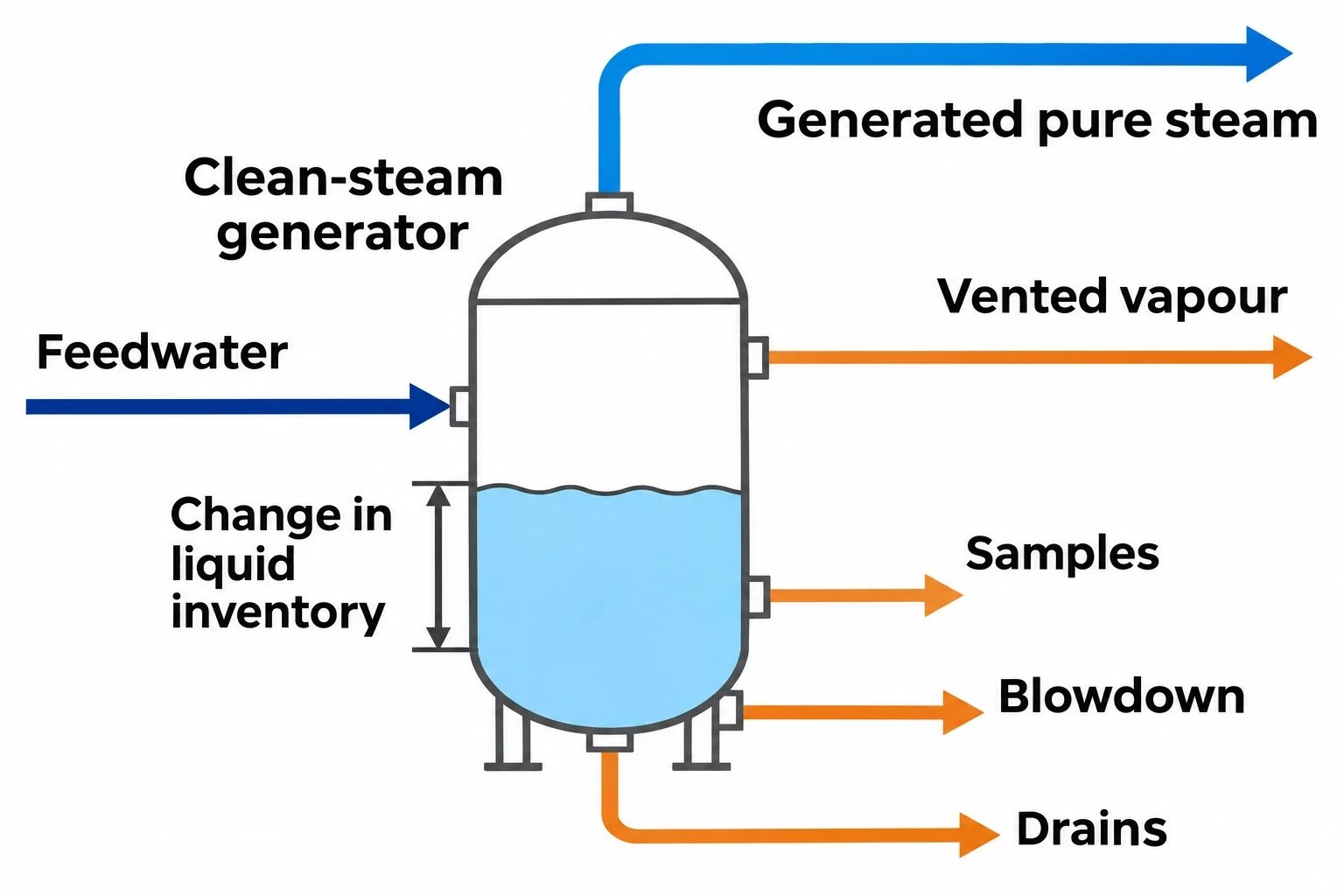
A heat and mass balance establishes where clean steam is generated, consumed, condensed, vented or lost. It prevents teams from mistaking a distribution fault or control issue for a generator-capacity deficit.
Define operating states, not one annual average
Pharmaceutical demand is often discontinuous. Sterilisers, vessel steam-in-place cycles and equipment heat-up periods can create short peaks that a monthly average cannot show.
A useful balance separates at least four conditions:
- Cold start and distribution warm-up.
- Warm standby.
- Normal production demand.
- Coincident peak demand from overlapping validated cycles.
Each condition should use time-aligned measurements of feedwater flow, generator output, utility-side heat input, header pressure, critical-point pressure and steriliser cycle status. The resulting model can reveal whether a pressure fall arises from evaporation duty, feedwater limitation, plant-steam variability, control-valve response or several users beginning heat-up together.
Account for each mass route
Over a defined operating period, feedwater entering the generator should be reconciled against pure-steam production, blowdown, vented vapour, drains, samples and changes in liquid inventory. The difference between calculated and metered values provides investigation targets.
High blowdown may indicate conservative operating practice, poor feedwater control or an issue requiring further investigation. Repeated venting can indicate unstable pressure control or unsuitable start-up sequencing. Frequent condensate discharge at a remote low point may indicate heat loss, poor pipe fall or trap performance.
The balance does not replace field inspection or steam-quality testing. It identifies where they should focus.
Map the energy as well as the water
The energy map should separate:
- Heat transferred from plant steam or electrical input.
- Sensible heat added to purified feedwater.
- Latent heat carried in generated pure steam.
- Heat rejected in blowdown and venting.
- Heat loss from the generator and distribution network.
- Energy associated with warm-up and standby.
This approach ranks measures by measured thermal effect and establishes a controlled baseline for comparison after implementation. The stream table should identify data sources, sampling period, assumed physical properties, meter uncertainty and the operating state represented.

Map every energy and material flow in your process with detailed heat and mass balance calculations — the foundation for any optimisation or design project.
Where clean steam energy and capacity are lost
The most reliable projects remove measured losses before attempting to reduce setpoints or generator capacity.
Distribution heat loss and start-up condensate
Heat loss from saturated-steam pipework produces condensate. Damaged or wet insulation, exposed valves and uninsulated fittings can affect both fuel use and steam dryness.
Cold starts deserve separate analysis. A cold header requires heat to raise pipework temperature, produce start-up condensate and establish stable pressure. Frequent short production windows can make warm-up demand a material part of total consumption.
A documented comparison can assess warm standby against repeated cold starts, including energy use, production timing and measured steam-quality performance at critical points of use. The chosen arrangement must remain consistent with validated availability and sterilisation requirements.
Traps, low points and pipe fall
Steam traps must remove condensate without continuously passing live steam. A failed-open trap wastes steam. A failed-closed, undersized or incorrectly selected trap can allow condensate to accumulate, increasing the risk of water hammer, wet steam and load-drying problems.
Annex 1 paragraph 6.5 makes current information on slopes, drains and user points part of the lifecycle record. Engineers should verify the as-built installation rather than rely solely on historic drawings. Later branch additions, support movement and building work can introduce low points absent from the original design.
Coincident demand and apparent generator constraints
A pure steam generator may appear undersized when several users enter heating stages at once. The demand profile, rather than nominal generator duty, can create the constraint.
Time-based modelling can test alternative start times for validated cycles. Staggering heat-up periods may lower peak header load and release capacity without altering sterilisation exposure parameters. The change still requires assessment against approved load patterns, cycle timing, equipment availability and the conditions supporting sterilisation efficacy.
How to optimise under Annex 1 change control
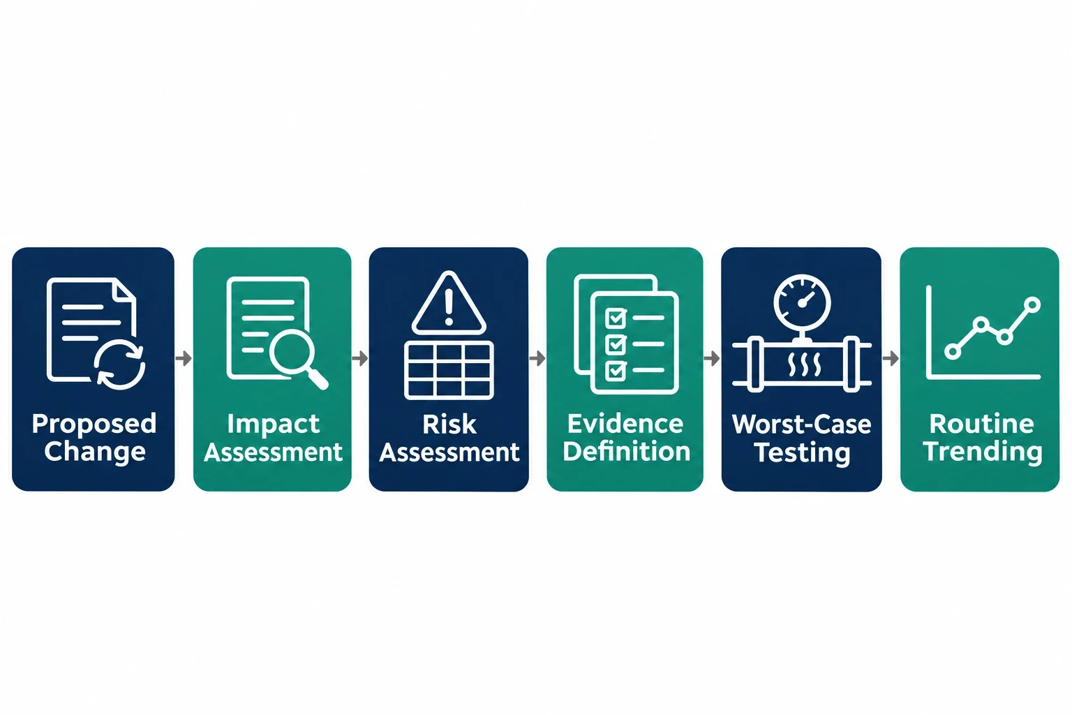
The evidence package depends on the scale and GMP impact of the proposed change. A new insulation section and a major generator-pressure change do not present the same risk, but both require documented evaluation where they can affect utility performance.
Define the GMP impact before implementation
The change assessment should identify whether the proposal affects:
- Defined pure-steam quality, including condensate expectations for direct sterilisation duties.
- Dryness value, superheat or non-condensable gases.
- Pressure and temperature at the steriliser or steam-in-place system.
- Air removal, equilibration time, exposure time and load drying.
- Sampling locations, sampling frequency or sample representativeness.
- Alert levels, action limits and adverse-trend review.
The Contamination Control Strategy should explain how the modification maintains control of microbial, endotoxin, particulate and chemical contamination risks. Maintenance work that changes a branch, trap, separator or sampling point can require wider assessment where it affects a critical utility attribute.
Match qualification evidence to the change
A risk assessment should define the evidence required before the modified system returns to routine operation. Depending on the change, this may include revised drawings, installation checks, commissioning data, point-of-use steam-quality testing, review of affected sterilisation cycles and post-change trending.
A material change should test conditions most likely to reveal reduced performance, including a remote point of use, the first cycle after shutdown, low normal demand and coincident demand. For steam-in-place applications, the review should confirm that routine monitoring remains representative of the validated slowest-to-heat locations.
The record must demonstrate more than a satisfactory commissioning result. It must show continued control across the normal operating range on which production depends.
Trend clean steam performance after release
Annex 1 paragraph 6.4 requires regular trend analysis for high-risk utility parameters and critical quality attributes. The post-change period should therefore form part of the optimisation deliverable.
Use utility and sterilisation indicators together
Generator pressure alone cannot establish control. A useful review combines utility data with process performance:
| Indicator | What it can reveal |
|---|---|
| Pure-steam flow per sterilisation cycle | Changes in demand, losses or operating practice |
| Feedwater use and blowdown rate | Generator efficiency, feedwater control and potential wastage |
| Utility-side heat input | Thermal impact of the project |
| Point-of-use pressure and temperature | Distribution behaviour during demand changes |
| Condensate quality results | Continued conformance for direct sterilisation duties |
| Dryness, superheat and non-condensable gas results | Physical steam-quality performance |
| Steriliser alarms, failed cycles and load-drying observations | Effects on validated process operation |
Alert-level excursions and adverse trends should be documented, reviewed and investigated. A shift in steam use may be beneficial; a simultaneous shift in pressure stability, condensate quality or failed-cycle frequency demands a different conclusion.
This article reflects the independent analysis and editorial opinion of EnerTherm Engineering. Product names, trademarks, and brands mentioned belong to their respective owners. EnerTherm Engineering is not affiliated with, endorsed by, or a licensee of any third-party software or product mentioned unless explicitly stated.

Managing Director — EnerTherm Engineering
Dr. François Pierrel is Managing Director of EnerTherm Engineering with over two decades of expertise in thermal design, heat transfer, and industrial energy optimisation. He holds a PhD in Heat Transfer from Cranfield University and a Post-Doctorate from Heriot-Watt University.
