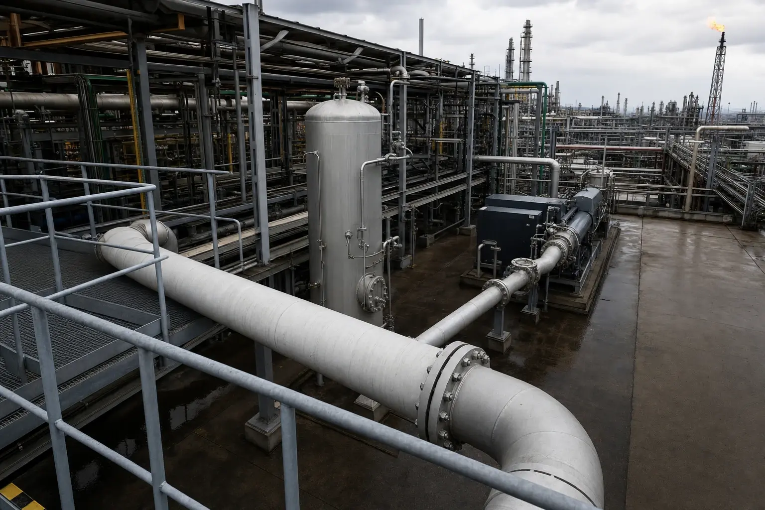
Refinery Flare Gas Recovery Analysis: What HMB Reveals
Measured flare flow, composition and LHV quantify fuel-gas potential and emissions savings.
A refinery flare-gas recovery analysis is a heat and mass balance that quantifies gas sent to flare, resolves its composition and lower heating value, and determines the fraction that can safely return to the refinery fuel-gas system.
Comodi, Renzi and Rossi’s 2016 feasibility study of an Italian refinery selected recovery capacity of 400 kg/h for gas with a lower heating value of 39,951 kJ/kg. At those values and 8,000 operating hours, the gross energy flow equates to 127.8 TJ before compression and treatment loads. The authors estimated annual energy recovery of 2,900 toe and reported 6,600 tonnes CO₂e for their site case.
These figures show the value that may be hidden in a flare header, but they are not a design basis for another refinery. Flare gas changes with crude slate, unit operation, relief activity, purge practice, hydrogen balance and fuel-gas demand. A sound refinery flare-gas recovery analysis establishes what is consistently available, what is usable and what must remain in the flare system.
A flare is a safety device. Recovery equipment should capture recurring, controllable flaring while maintaining a direct, reliable route for emergency and relief loads.
Why refinery flare gas recovery analysis begins with HMB
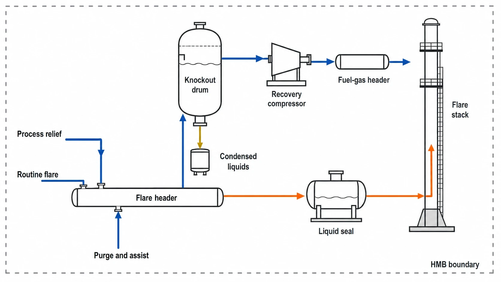
A compressor vendor can estimate capacity once flow, pressure, composition and variability are known. Those inputs are the output of the HMB, not its starting point.
The HMB sets a defined process boundary around the flare system and connects it to the refinery fuel-gas network. It reconciles gas sources, liquids removed upstream of the flare, purge and assist media, fuel-gas demand and the proposed recovery route. This converts a flare rate into an engineering case.
Establish the flare-system boundary
The boundary should run from source units through relief headers, subheaders, knockout drums, liquid seals, purge connections and flare stacks. For recovery screening, it should continue through the proposed knockout and compression equipment to a defined fuel-gas header or alternative consumer.
Several streams need explicit treatment in the mass balance:
- Process relief, depressurisation and blowdown gas.
- Routine low-rate flare flow from operating units.
- Pilot and purge gas.
- Steam, air or fuel gas used for flare assistance.
- Condensed hydrocarbons collected in knockout drums.
- Vapour from tanks, loading systems and maintenance activities.
- Nitrogen, carbon dioxide, hydrogen sulphide and other non-hydrocarbon components.
A meter at the flare header records flow. It does not establish how much combustible gas remains after dilution, liquid removal and treatment.
Separate recurring flow from event-driven flow
The HMB should classify flare activity by cause and duration. Continuous low-rate flaring may indicate a recoverable base load. Planned start-up and shutdown flaring may require operating changes, storage or flexible equipment. Short relief events define the safety case, but do not normally determine recovery capacity.
This avoids sizing equipment from a simple annual average. A compressor selected on that basis may be oversized for normal operation or unable to operate efficiently through the low-flow periods that dominate the year.
A source-by-source register should record the unit, source mechanism, typical duration, estimated mass flow, composition, event frequency and whether operations can eliminate the source. It often identifies low-cost operational work before a capital recovery project proceeds.

Map every energy and material flow in your process with detailed heat and mass balance calculations — the foundation for any optimisation or design project.
Measuring flare gas for a credible HMB
A refinery flare-gas recovery analysis depends on data with a common basis. Historic distributed-control-system trends can support initial screening. Front-end engineering needs time-aligned flow, pressure, temperature, composition and source-unit operating data.
Use continuous flow data with a clear reference basis
Flare measurement should cover normal running, maintenance periods, transitions, feed changes and known upset conditions. The balance must state whether each measurement is actual volume, normalised volume, mass flow or energy flow.
Pressure, temperature, molecular weight and flowmeter configuration matter. A value in Nm³/h cannot be compared directly with a fuel-gas flow unless both normalisation bases are known. Check flow data against event logs, relief activity, header pressures and unit operating records.
Duration curves are particularly useful. A mass-flow duration curve shows operating hours above a proposed recovery rate. An energy-flow duration curve adds heating value and can expose periods when a high volumetric flare rate carries little recoverable fuel.
Build composition into the measurement plan
Gas chromatograph results provide molecular weight, density, lower heating value and the chemical constraints on reuse. Representative samples should cover flare conditions that materially affect equipment and fuel-gas quality, rather than a single convenient operating period.
The analysis should normally resolve:
| Component group | HMB purpose |
|---|---|
| Hydrogen and methane | Heating value, density and fuel-gas quality |
| Ethane, propane, butanes and C₅+ | Fuel value, condensation risk and liquid load |
| Nitrogen and carbon dioxide | Inert dilution and compressor volumetric load |
| Hydrogen sulphide and mercaptans | Sulphur loading, treatment and materials selection |
| Water vapour and oxygen, where relevant | Corrosion, combustion and process-safety assessment |
A high hydrogen content may affect density and heating value despite its modest mass contribution. Nitrogen and carbon dioxide increase compressor throughput without adding fuel value. Hydrocarbon-rich gas can provide valuable refinery fuel, but heavy components increase the need for dependable liquid separation.
Reconcile measurements against plant constraints
An HMB should not accept every field measurement without challenge. Engineers reconcile flare flow, source-unit estimates and downstream fuel-gas consumption against physical constraints such as header pressure, known purge rates, flare-knockout liquid production and recorded operating events.
Material discrepancies often reveal an incorrect normalisation basis, unmeasured purge, an omitted flare source, an unreliable flowmeter or liquid carry-over. Resolving them improves the recovery study and the refinery’s flare-management data.
What the mass balance reveals about recoverability
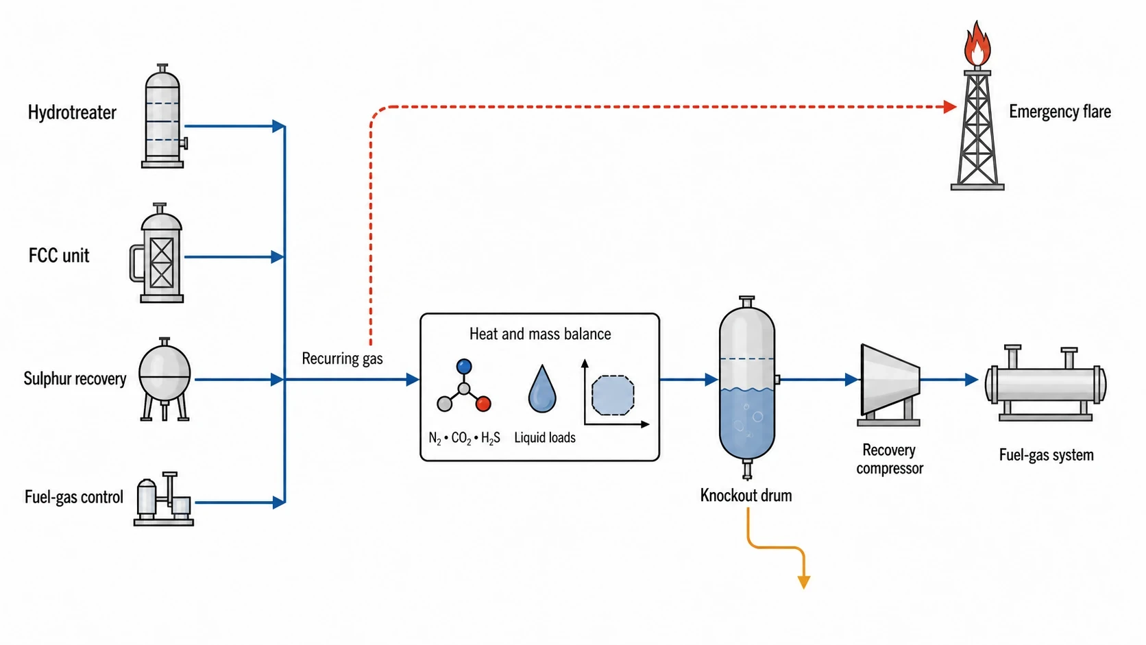
Recoverable flare gas is a defined operating fraction, not the annual total at the flare tip. The HMB identifies its stability, contaminants and the limits imposed by the receiving system.
Determine the stable recovery envelope
The recovery envelope should include minimum, typical and maximum recurring flow conditions, as well as rate of change, pressure variation and composition changes. A viable system requires controllable operation at the lower end of the recurring range and sufficient capacity at higher routine loads.
The result normally defines recovery capacity below the peak flare rate. The recovery package handles normal gas available for reuse, while the flare retains its required disposal function during rapid excursions.
Link the recurring fraction to individual source units. A hydrotreater, fluid catalytic cracking unit, sulphur recovery system or fuel-gas pressure-control arrangement may each create a distinct flare signature. Their root causes and remedies differ.
Quantify inerts and sour-gas loading
Inerts reduce the energy recovered per unit of compressor throughput. The HMB should calculate nitrogen and carbon dioxide as mass, molar and volumetric fractions, then show their effect on lower heating value and fuel-gas blending.
Hydrogen sulphide needs the same treatment. Concentration alone does not define the treatment case. Annual hydrogen sulphide mass loading determines the potential duty on an existing acid-gas removal or sulphur-handling system, with implications for metallurgy, condensate disposal and fuel-gas specifications.
A sour or inert-rich source can weaken an otherwise attractive recovery case. Engineers may assess segregation, treatment, blending restrictions or source reduction according to the receiving fuel-gas system and the refinery’s sulphur balance.
Include condensed hydrocarbons in the balance
Flare headers can carry liquid droplets, condensed hydrocarbons and water. A representative gas sample does not replace a liquid balance.
The HMB should identify expected liquid loads to knockout drums and estimate vapour-liquid behaviour across the recovery system’s pressure and temperature range. This sets knockout volume, drainage arrangements, demisting requirements, compressor protection and condensate-handling capacity.

Map every energy and material flow in your process with detailed heat and mass balance calculations — the foundation for any optimisation or design project.
Converting recovered gas into refinery fuel-gas potential
An annual flare-energy number is only the first result. The refinery needs to know when recovered gas is available and whether fuel-gas consumers can accept it.
Match energy supply to fuel-gas demand
The HMB should compare recovered-gas energy with refinery fuel-gas supply and demand by operating case. The assessment should consider fuel-gas-header pressure, heating value, hydrogen content, inert content, hydrogen sulphide limits and fired-heater requirements.
The key question is displacement. Recovered flare gas provides a net fuel benefit when it displaces imported natural gas or another marginal fuel source. A header already carrying excess refinery fuel gas may require a different destination, lower process off-gas generation or further operating changes.
This view also identifies effects on fired-heater combustion control, sulphur-emissions performance and refinery fuel-gas balancing.
Calculate net, rather than gross, energy recovery
The recovered-gas lower heating value is gross fuel potential. Net recovery deducts the energy and utilities needed to make the gas usable.
The HMB should include:
- Compressor electrical demand.
- Intercooler and aftercooler duties.
- Cooling-water or air-cooler loads.
- Seal-liquid circulation where applicable.
- Gas-treatment utilities and solvent circulation.
- Knockout, condensate pumping and associated auxiliary loads.
Comodi, Renzi and Rossi selected a liquid-ring compressor for a variable refinery flare-gas case with inert gases and hydrogen sulphide treatment. That choice reflects conditions at their Italian refinery. Compression technology should follow the site-specific HMB, including pressure ratio, gas composition, turndown, liquid carry-over, corrosivity, reliability targets and maintenance requirements.
Emissions and permitting in UK and EU refinery flare recovery
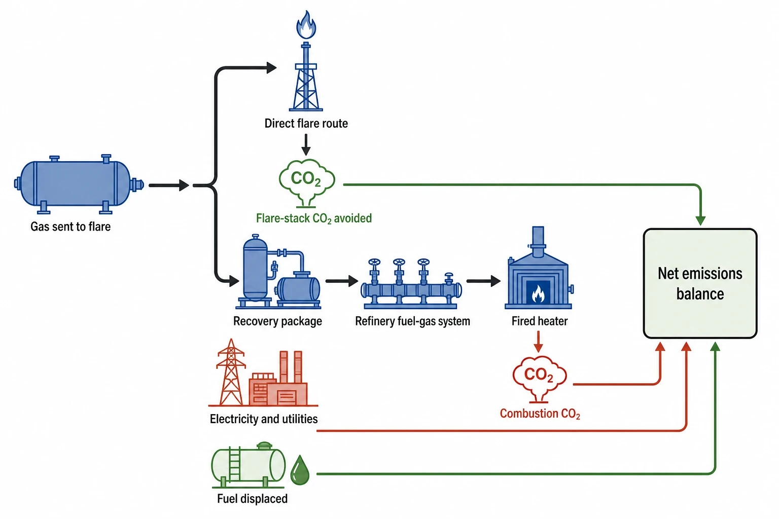
A flare-recovery project can reduce gas sent to flare, but carbon reporting must identify the fuel displaced and the energy consumed by the recovery package. Combusting recovered gas in a fired heater still produces carbon dioxide.
Set a clear emissions boundary
The emissions balance should distinguish between flare reduction and net emissions reduction. It should report gas diverted from the flare, flare-stack carbon dioxide avoided, carbon dioxide generated when recovered gas is combusted, electricity and utility emissions, and fuel displaced at the refinery boundary.
The 2,900 toe annual energy recovery and 6,600 tonnes CO₂e reported by Comodi, Renzi and Rossi apply to their 2016 case study, not as a generic factor. Refinery fuel substitution, electricity-emissions factors, flare-combustion performance and monitoring methods vary by location and configuration.
Apply the correct refinery BAT conclusions
Commission Implementing Decision (EU) 2016/902 concerns common waste-water and waste-gas treatment and management systems in the chemical sector. It is not the refinery BAT decision.
For mineral-oil and gas refining, Commission Implementing Decision 2014/738/EU is the relevant EU decision. BAT 55 limits flaring to safety reasons and non-routine conditions, including start-ups and shutdowns. BAT 56 addresses unavoidable flaring through plant design, plant management, flare-device design, monitoring and reporting. It identifies flare-gas recovery retrofit, fuel-gas balancing and advanced process control among the relevant measures.
BAT 56 also describes continuous monitoring of gas sent to flare, measurement of flow and estimation of composition and heat content. These requirements align with the measurement basis of a refinery flare-gas recovery analysis.
Directive (EU) 2024/1785 amended the Industrial Emissions Directive. For existing EU installations, the Directive 2010/75/EU framework continues to apply until relevant transition dates, including permit updates and new BAT conclusions. EU refinery teams should review the national permit, current refinery BAT conclusions and the Member State’s transposition arrangements.
Use the relevant UK permit basis
In Great Britain, EU BAT conclusions published before 1 January 2021 were retained in domestic law and are treated within the assimilated-law framework. The position is not that EU BAT conclusions continue solely through the European Union (Withdrawal) Act 2018. Environmental permits provide the enforceable, installation-specific route through which the Environment Agency, Natural Resources Wales or SEPA applies BAT requirements.
The UK is developing UK BAT conclusions. Existing EU refinery BAT material remains relevant to permit assessment until replacement UK conclusions and permit changes apply. Northern Ireland has a distinct position under the Windsor Framework arrangements, so refinery teams there should confirm applicable EU and domestic requirements with the regulator.
The Greenhouse Gas Emissions Trading Scheme Order 2020 establishes the UK ETS. Its monitoring, reporting and verification requirements make the flare HMB valuable beyond project economics: consistent flow, composition, calorific-value and event records support the installation’s approved monitoring approach.
Taking refinery flare gas recovery analysis to FEED
A screening study should end with a defined recovery envelope and a clear list of decisions, not a headline energy figure. The HMB provides the evidence for front-end engineering design and a refinery investment decision.
Produce the engineering deliverables
A FEED-ready refinery flare-gas recovery analysis should provide:
- A reconciled process flow diagram with stream tables.
- Source-by-source flare-loss register.
- Normal, minimum and maximum recovery cases.
- Mass, molar and energy balances for flare and fuel-gas systems.
- Duration curves for flow and energy.
- Hydrogen sulphide, inert and condensate balances.
- Compressor, treatment and utility design loads.
- Fuel-gas-header acceptance analysis.
- Flare-management monitoring and data-assurance requirements.
An EnerTherm Engineering HMB can apply its 11-step methodology from scope definition and site-data collection through steady-state modelling, reconciliation, operating-case testing and FEED-ready documentation. The resulting process flow diagram should make the decision auditable across operations, process engineering, energy management and environmental compliance.
Turn the balance into an operating roadmap
The preferred sequence is often operational before capital. Engineers should first eliminate avoidable recurring sources, correct fuel-gas-balancing issues and improve control of source units. The remaining stable stream can then be assessed for compression, treatment and return to fuel gas.
This article reflects the independent analysis and editorial opinion of EnerTherm Engineering. Product names, trademarks, and brands mentioned belong to their respective owners. EnerTherm Engineering is not affiliated with, endorsed by, or a licensee of any third-party software or product mentioned unless explicitly stated.

Managing Director — EnerTherm Engineering
Dr. François Pierrel is Managing Director of EnerTherm Engineering with over two decades of expertise in thermal design, heat transfer, and industrial energy optimisation. He holds a PhD in Heat Transfer from Cranfield University and a Post-Doctorate from Heriot-Watt University.
