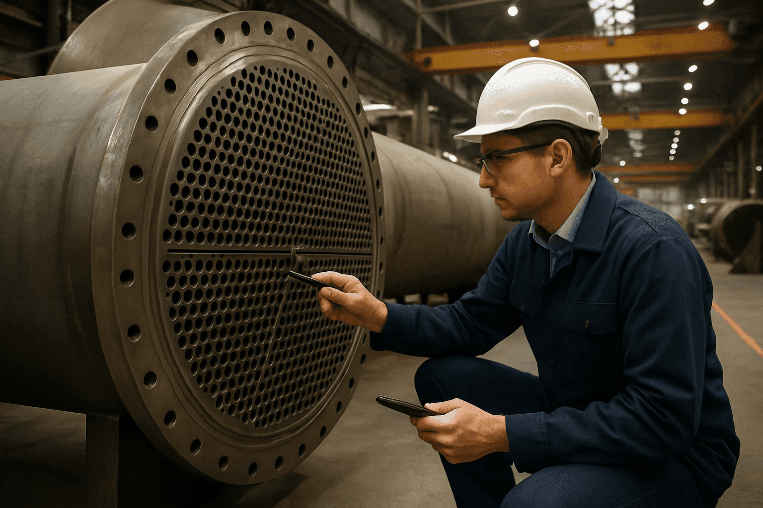
Mastering Shell and Tube Heat Exchanger Design for Extreme Temperature Gradients
Shell and tube heat exchangers (STHEs) are workhorse components across a multitude of industries, including industrial manufacturing, chemical processing, power generation, and oil refining. Their robust design and adaptability make them suitable for various applications. However, designing STHEs for extreme temperature gradients introduces a unique set of engineering challenges. This article delves into the critical considerations and best practices for designing STHEs capable of withstanding and effectively managing substantial temperature differences between the fluids they handle.
Understanding the Challenges of Extreme Temperature Gradients
Extreme temperature gradients, typically seen when the temperature difference between the hot and cold fluids is significant, pose several challenges to the design and operation of STHEs:
-
Thermal Stress: Large temperature differences induce significant thermal stresses within the heat exchanger components, especially in the tubes, tubesheets, and shell. Uneven expansion and contraction can lead to material fatigue, creep, and ultimately, failure.
-
Material Selection: The materials used in STHE construction must withstand high temperatures and temperature fluctuations while maintaining their mechanical strength and corrosion resistance. Finding materials that meet these criteria and are cost-effective can be challenging.
-
Differential Thermal Expansion: Different components of the heat exchanger (tubes, shell) expand and contract at varying rates due to temperature differences. This differential expansion can cause stress on joints and connections, leading to leaks and structural damage.
-
Heat Transfer Efficiency: Maintaining optimal heat transfer efficiency under extreme temperature gradients requires careful consideration of fluid flow patterns, tube arrangement, and baffle design.
-
Fouling: High temperatures can accelerate fouling, where unwanted deposits accumulate on heat transfer surfaces, reducing efficiency and increasing pressure drop.
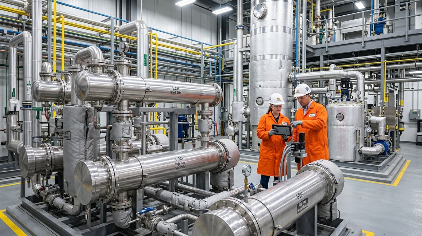
Recover waste heat and cut fuel costs with shell & tube or air-to-air exchangers engineered for continuous industrial duty.
Key Design Considerations
Designing STHEs for extreme temperature gradients requires careful attention to several key factors:
1. Material Selection
Selecting appropriate materials is paramount. The materials must possess high thermal conductivity, sufficient mechanical strength at elevated temperatures, and resistance to corrosion from the working fluids. Common materials include:
-
Carbon Steel: Suitable for moderate temperatures and non-corrosive fluids due to its strength and affordability. However, it requires protection against corrosion.
-
Stainless Steel: Offers excellent corrosion resistance and strength, particularly at high temperatures. Grades like 304, 316, and 316L are commonly used.
-
Duplex Stainless Steel: Combines high strength and corrosion resistance, making it suitable for highly corrosive environments.
-
Nickel Alloys (e.g., Inconel, Hastelloy): Provide exceptional durability in extreme corrosion and high-temperature conditions. These are often used when handling chemically aggressive fluids.
-
Copper Alloys: Offer good heat transfer and moderate corrosion resistance, often used in marine and HVAC systems.
-
Titanium: Outstanding corrosion resistance and lightweight, ideal for seawater and aggressive chemicals. However, it is expensive and difficult to fabricate.
The choice depends on balancing performance, cost, and ease of fabrication. For instance, when dealing with high-temperature gases, specialised materials like Inconel 617, Inconel 625, 800H, Haynes 230, and Haynes 120 may be necessary.
2. Thermal Stress Management
Mitigating thermal stress is crucial for ensuring the longevity of the STHE. Strategies include:
-
Expansion Joints: Incorporating expansion joints in the shell to absorb thermal expansion and reduce stress on the tubesheet and shell.
-
U-Tube Design: Utilising U-tube designs, where the tubes are bent into a U-shape, allows for thermal expansion and contraction without putting excessive stress on the tubesheet. However, cleaning U-tubes can be challenging.
-
Floating Head Design: Employing floating head designs, where one tubesheet is allowed to move freely, accommodates differential expansion between the shell and tubes. Common types of tube sheets used in lower temperature STHEs aren't always suitable in high-temperature applications.
-
Thermal Stress Analysis: Conducting thorough thermal stress analysis using Finite Element Analysis (FEA) to identify high-stress areas and optimise the design to minimise stress concentrations. This analysis should consider both normal operating conditions and upset scenarios with extreme temperature differentials.
3. Heat Transfer Enhancement
Maximising heat transfer efficiency is critical, especially when dealing with extreme temperature gradients. Techniques include:
-
Baffle Design: Optimising baffle spacing, cut, and type to enhance turbulence and improve heat transfer coefficients on the shell side. Helical baffles can increase heat transfer efficiency and reduce pressure losses compared to traditional segmental baffles.
-
Tube Arrangement: Selecting an appropriate tube layout (triangular, square, rotated square) to balance heat transfer and pressure drop requirements.
-
Finned Tubes: Using finned tubes to increase the surface area for heat transfer, particularly when the heat transfer coefficient on one side is significantly lower than the other. However, in high-temperature environments with fouling potential, the effectiveness of fins may be limited.
-
Counterflow Arrangement: Implementing a counterflow arrangement, where the hot and cold fluids flow in opposite directions, maximises the temperature gradient and enhances heat transfer efficiency.
4. Fouling Mitigation
Minimising fouling is essential to maintain heat exchanger performance. Strategies include:
-
High Tube-Side Velocities: Designing for high tube-side velocities to increase shear stress and reduce the deposition of fouling materials. However, this must be balanced with pressure drop considerations.
-
Proper Fluid Selection: Selecting fluids that are less prone to fouling.
-
Regular Cleaning: Implementing a regular cleaning schedule to remove fouling deposits. Designs that allow for easy mechanical or chemical cleaning are advantageous.
-
Anti-Fouling Coatings: Applying anti-fouling coatings to the tubes to reduce the adhesion of fouling materials.
5. Welding and Fabrication Techniques
Proper welding and fabrication techniques are crucial for ensuring the structural integrity of the STHE, especially under extreme conditions. Considerations include:
-
Welder Certification: Employing certified welders with expertise in welding exotic materials and dissimilar metals.
-
Welding Procedures: Utilising appropriate welding procedures to minimise residual stresses and ensure weld quality.
-
Post-Weld Heat Treatment: Performing post-weld heat treatment to relieve stresses and improve the mechanical properties of the weld.
-
Non-Destructive Examination (NDE): Conducting thorough NDE, such as radiographic testing and ultrasonic testing, to detect any weld defects.
6. Design Codes and Standards
Adhering to relevant design codes and standards is essential for ensuring the safety and reliability of the STHE. Key standards include:
-
TEMA Standards: Provides guidelines for the design, manufacturing, and inspection of shell and tube heat exchangers.
-
ASME Boiler and Pressure Vessel Code (BPVC), Section VIII: Covers the design, manufacturing, testing, and inspection of pressure vessels, including heat exchangers.
-
API Standard 660: Specifically addresses shell and tube heat exchangers in the petroleum and petrochemical industries.
-
EN 13445: European standard for unfired pressure vessels.
-
PD 5500: British standard for unfired pressure vessels.
7. Addressing Operational Considerations
-
Start-up and Shut-down Procedures: Gradual heating and cooling during start-up and shut-down minimises thermal shock.
-
Vibration Analysis: Assessing the potential for flow-induced vibration and implementing measures to mitigate it, such as support baffles.
-
Monitoring and Maintenance: Regular inspections and monitoring of key parameters (temperatures, pressures, flow rates) help detect potential problems early.
Designing a Well-Insulated Shell-and-Tube Heat Exchanger
In processes involving extreme temperature gradients, utilising a well-insulated shell-and-tube heat exchanger is critical. High temperature differentials between the process fluids and the surrounding environment lead to massive radial heat fluxes. Proper thermal insulation is not merely a method of conserving energy; it is a vital mechanical design intervention that controls thermal expansion gradients across the shell, protects plant operators from burns, and prevents local atmospheric condensation that accelerates corrosion.
Thermal Resistance and Heat Loss Calculations
To evaluate the heat loss and temperature drop across the outer boundaries of a well-insulated shell-and-tube heat exchanger, engineers model the system as a series of radial thermal resistances. The rate of heat loss (Qloss) from the shell to the ambient atmosphere through a multi-layer cylindrical insulation system is calculated using the following formula:
Qloss=hinnerr11+ksteelln(r2/r1)+kinsln(r3/r2)+houterr312πL(Tshell−Tambient)where:
- Qloss is the total thermal loss from the shell (W)
- L is the length of the insulated exchanger shell (m)
- Tshell is the bulk temperature of the shell-side fluid (°C)
- Tambient is the ambient environmental temperature (°C)
- r1 is the inner radius of the steel shell (m)
- r2 is the outer radius of the steel shell / inner radius of the insulation (m)
- r3 is the outer radius of the insulation cladding (m)
- ksteel is the thermal conductivity of the shell material (W/m·K)
- kins is the thermal conductivity of the chosen insulation material (W/m·K)
- hinner is the convective heat transfer coefficient of the shell-side fluid (W/m²·K)
- houter is the combined radiative and convective external heat transfer coefficient to the atmosphere (W/m²·K)
By increasing the thickness of the insulation (increasing r3), the term kinsln(r3/r2) becomes the dominant resistance in the denominator. This minimises heat dissipation, ensuring the system functions efficiently as a well-insulated shell-and-tube heat exchanger.
The sequence below illustrates the thermal barrier pathway from the high-temperature shell-side process fluid to the atmosphere:
Insulation Material Selection
When selecting thermal insulation materials for extreme temperature systems, several factors must be weighed, including maximum service temperature, thermal conductivity, mechanical compressive strength, and water absorption characteristics:
- Mineral Wool: Outstanding thermal performance up to 650 °C. It is non-combustible and offers excellent acoustic dampening, making it a standard choice for refinery and chemical plant STHEs.
- Calcium Silicate: Highly durable with high compressive strength, capable of withstanding temperatures up to 1000 °C. It is highly resistant to physical damage but is prone to moisture absorption if the protective cladding is compromised.
- Pyrogenic Silica Aerogels: Offer extremely low thermal conductivity (kins≈0.015 to 0.020 W/m·K), allowing for a significantly thinner insulation profile. This is ideal for space-constrained installations or highly complex piping manifolds.
- Cellular Glass: Impervious to water and chemical fumes, eliminating the risk of water absorption. It is limited to moderate-to-high temperatures (up to 480 °C) but provides excellent protection against corrosion under insulation (CUI).
Mitigating Corrosion Under Insulation (CUI)
A primary failure mode for any well-insulated shell-and-tube heat exchanger is Corrosion Under Insulation (CUI). CUI occurs when water penetrates the insulation cladding and becomes trapped against the hot carbon steel or stainless steel shell surface. To prevent this:
- Apply high-performance organic or thermal-sprayed aluminium (TSA) coatings to the exterior of the shell prior to installing insulation.
- Ensure the outer protective cladding (typically aluminium or 316 stainless steel) is fully sealed with high-temperature silicone sealants.
- Incorporate drain plugs or "weep holes" at the lowest points of the insulation cladding to allow any ingress moisture to escape harmless only.
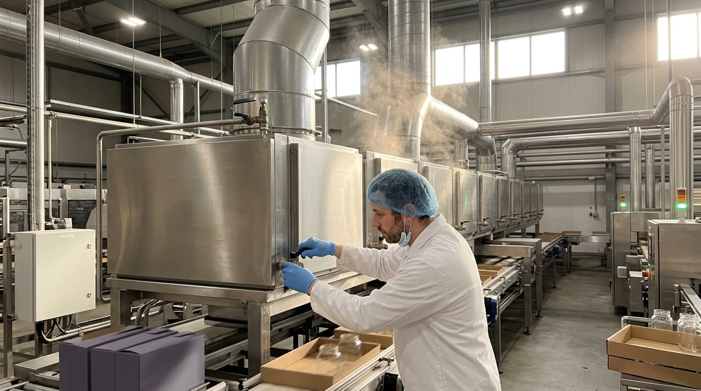
Our ThermStack and EcoStream heat exchanger ranges deliver measurable energy savings across chemical, food, pharma, and power generation processes.
Innovative Designs and Technologies
Emerging technologies and design innovations are continuously improving the performance and reliability of STHEs in extreme temperature gradient applications:
-
Compact Heat Exchangers: Designs that maximise heat transfer within a minimised footprint, often utilising enhanced tube geometries.
-
Multi-Tube Heat Exchangers: Suitable for high-pressure applications, these designs allow for full dismantling for inspection and cleaning.
-
Graphite Composite Materials: Offering resistance to fluoride salts, acids, and bases, graphite composites are applicable for molten salt reactors and the chemical industry.
-
Twisted Tube Exchangers: Featuring twisted tubes that support each other, these designs provide higher heat transfer coefficients and reduced pressure drop.
Case Studies and Examples
-
High-Pressure Heater for Well Testing: Bronswerk Heat Transfer delivered a Multi-Tube Heat Exchanger suitable for well testing for Expro Group that could be fully dismantled for inspection.
-
Titanium Finned Tube Heat Exchanger: High Performance Tube demonstrated the use of titanium integral finned tube in a compact shell and tube heat exchanger design. The increased shellside heat transfer surface area, reduction in tube thickness for external pressure, fouling resistance, and applicability to severe services were key advantages.
-
Feedwater Heaters in Power Plants: Thermo-structural fatigue and lifetime analysis of a shell-and-tube counter-flow heat exchanger as a feedwater heater in a power plant shows how thermal stresses at the joints of the tubes and tubesheet can be evaluated according to the ASME VIII Boiler and Pressure Vessel Code.
Conclusion
Designing shell and tube heat exchangers for extreme temperature gradients demands a comprehensive understanding of the associated challenges and a meticulous approach to design. By carefully considering material selection, thermal stress management, heat transfer enhancement, fouling mitigation, welding techniques, and adherence to industry standards, engineers can create robust, efficient, and reliable heat exchangers capable of operating safely and effectively under the most demanding conditions. Incorporating a well-insulated shell-and-tube heat exchanger further ensures that thermal energy is tightly controlled, protecting equipment, maximising thermodynamic efficiency, and guaranteeing long-term operational integrity.
