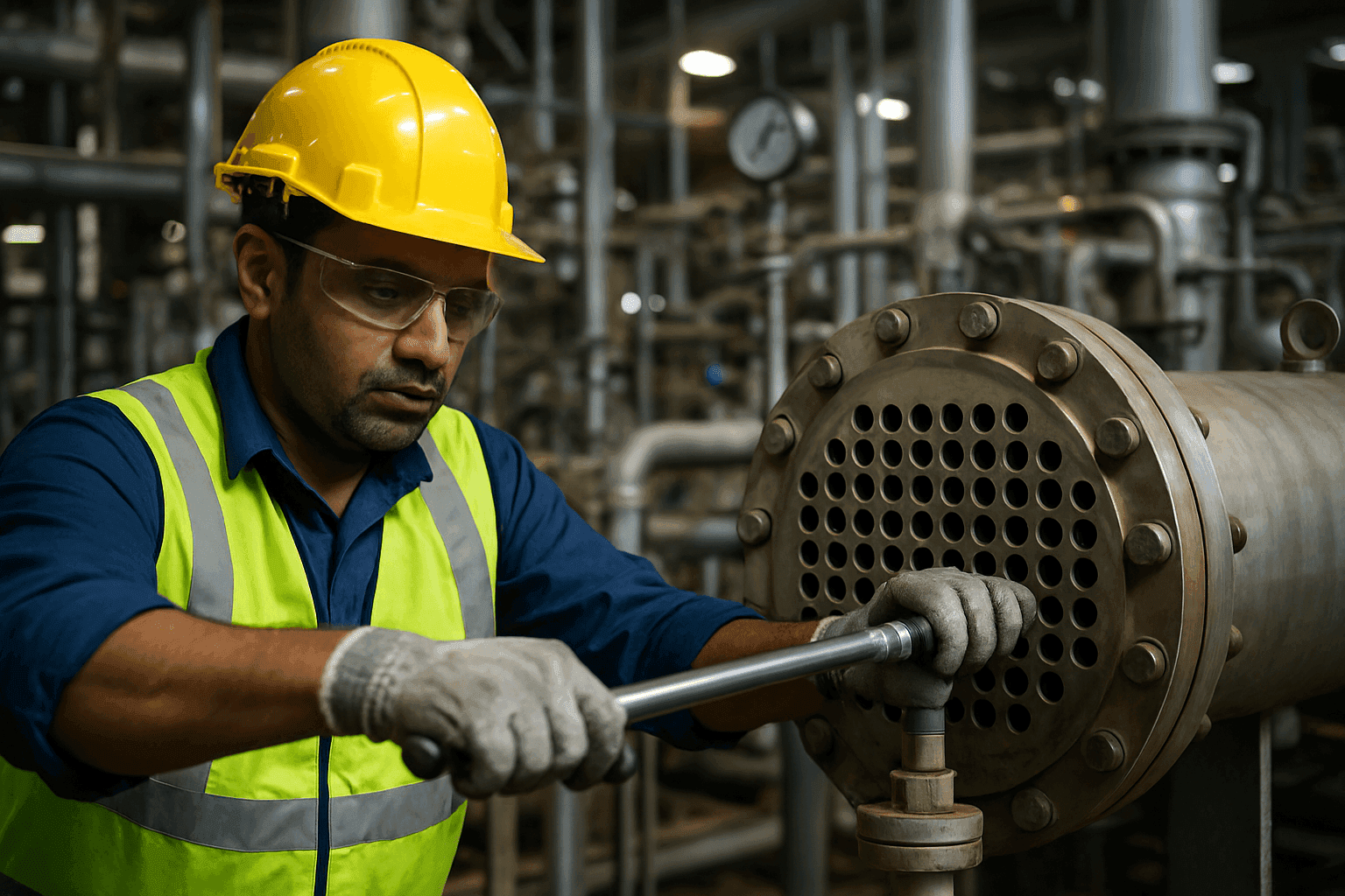
Mastering Shell and Tube Heat Exchanger Maintenance: Best Practices for Longevity and Efficiency
Shell and tube heat exchangers are the workhorses of industrial heat transfer, vital in sectors ranging from chemical processing and oil & gas to power generation and manufacturing. Their reliable operation is paramount, yet they are susceptible to various forms of degradation that can significantly reduce efficiency, increase energy consumption, and lead to costly downtime if not properly maintained. Implementing a robust maintenance strategy is not merely a reactive measure but a proactive investment in the longevity, safety, and optimal performance of these critical assets.
This comprehensive guide delves into the best practices for maintaining shell and tube heat exchangers, covering everything from routine inspections and effective cleaning methods—including automated tubeside cleaning—to understanding common failure mechanisms and leveraging advanced predictive technologies.
Why Shell and Tube Heat Exchanger Maintenance is Crucial
The efficiency of a shell and tube heat exchanger directly impacts the overall productivity and profitability of an industrial plant. Thermal performance is governed by the fundamental heat transfer equation:
Q=U⋅A⋅ΔTlmWhere:
- Q is the heat transfer rate (W)
- U is the overall heat transfer coefficient (W/m²K)
- A is the heat transfer surface area (m²)
- ΔTlm is the logarithmic mean temperature difference (K)
Over time, factors like fouling, corrosion, and erosion introduce a thermal resistance layer (Rf), which drastically reduces the overall heat transfer coefficient (U). Neglecting routine shell and tube heat exchanger maintenance can lead to:
- Decreased Heat Transfer Efficiency: Fouling acts as an insulator, reducing the rate at which heat is exchanged and forcing the system to work harder to achieve design temperatures.
- Increased Energy Consumption: Reduced thermal efficiency demands higher utility consumption (e.g. steam, cooling water, or electricity) to compensate for the degradation.
- Higher Pressure Drops: Blockages and rough surfaces due to scale deposits increase fluid resistance. This results in an elevated pressure drop (ΔP), requiring significantly higher pumping power.
- Component Damage and Premature Failure: Unchecked corrosion, erosion, or vibration can lead to leaks, tube ruptures, and permanent damage, necessitating expensive repairs or replacements.
- Unscheduled Downtime: Catastrophic failures result in unexpected shutdowns, halting production and incurring massive financial losses.
- Safety Hazards: Leaks and structural integrity issues can pose serious safety risks, especially when dealing with volatile, flammable, or hazardous process fluids.
Regular and well-planned maintenance is essential to mitigate these risks, ensuring continuous, safe, and efficient operation.
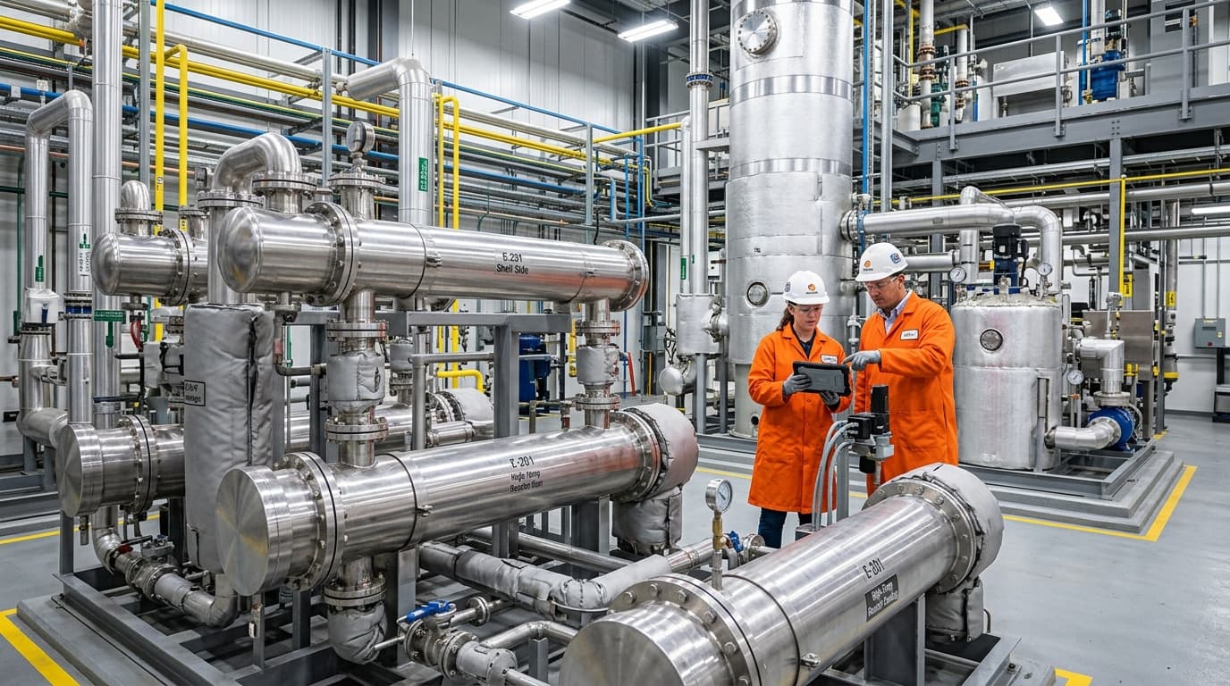
Recover waste heat and cut fuel costs with shell & tube or air-to-air exchangers engineered for continuous industrial duty.
When to Perform Heat Exchanger Maintenance
Identifying the optimal time for maintenance is key to a cost-effective operational strategy. Maintenance schedules should be determined by monitoring performance indicators rather than relying solely on arbitrary calendar intervals. Key triggers include:
- Visible Signs of Fouling: Accumulation of deposits like scale, sediment, or biological growth on the tube sheets or accessible surfaces.
- Reduced Thermal Efficiency: A calculable drop in the overall heat transfer coefficient (U) or a mismatch in design temperature profiles.
- Elevated Pressure Drops: An increase in pressure drop across the shell or tube side beyond the designated threshold (typically 10 to 15 per cent above clean baseline parameters).
- Presence of Slime or Algae: Indicates biological fouling on the cooling water side that requires immediate biocide treatment or physical cleaning.
- Chemical Incompatibility or Stubborn Deposits: Rapid degradation of process performance indicating chemical scaling, polymerisation, or carbonisation.
- Structural Anomalies: Visual indicators of compromise, such as weepage at tube-to-tubesheet joints, external rust, cracks, or deformation.
Essential Maintenance Practices and Procedures
An effective maintenance programme for shell and tube heat exchangers relies on a structured workflow that spans inspection, cleaning, and targeted mechanical repairs.
Routine Inspections and Monitoring
Regular inspections are the cornerstone of proactive heat exchanger maintenance, allowing engineers to identify and rectify minor defects before they escalate into structural failures.
- Visual Inspection: Conduct detailed external and internal visual checks for leaks, cracks, corrosion, and physical damage on the shell, tube bundle, channel covers, tube sheets, and welds. Inspect structural components including baffles, tie-rods, impingement plates, nozzles, and external supports. Monitor the condition of sacrificial anodes where fitted.
- Pressure and Temperature Monitoring: Verify the accuracy of pressure transmitters and thermocouples. Real-time logging of tube-side and shell-side thermal rise, temperature differentials (ΔT), and pressure drops (ΔP) helps identify fouling trends and optimal cleaning schedules.
- Fluid Analysis: Regularly analyse circulating fluids to monitor pH, suspended solids, biological activity, and contamination. Sudden changes can signal internal tube leaks or accelerated corrosion rates.
- Non-Destructive Examination (NDE) Techniques:
- Eddy Current Testing (ECT): The primary NDE method for non-ferromagnetic tubes (e.g. copper, brass, stainless steel, titanium). It detects wall thinning, pitting, cracking, and wear at baffle supports.
- Internal Rotary Inspection System (IRIS): An ultrasonic technique ideal for both ferrous and non-ferrous tubes. It provides precise, 360∘ wall-thickness measurements to map local corrosion and erosion.
- Magnetic Flux Leakage (MFL): Used rapidly to screen ferromagnetic carbon steel tubes for severe pitting, wall loss, and corrosion.
- Hydrostatic Testing: Involves isolating the shell or tube side, filling it with water, and pressurising the chamber (typically to 1.3 to 1.5 times the design pressure) to locate leaks in the tubes or tube-to-tubesheet joints.
- Borescope or Fibrescope Inspections: Allows internal visual assessment of the tubes to confirm cleaning efficacy or identify localised pitting.
- Adherence to Standards: All inspection and repair activities must comply with international industrial codes, specifically API 510 (Pressure Vessel Inspection Code, 11th Edition), API RP 572 (Inspection Practices for Pressure Vessels, 5th Edition), API RP 571 (Damage Mechanisms Affecting Fixed Equipment in the Refining Industry, 3rd Edition), and ASME Section VIII & IX (2025 Edition).
Cleaning Methods and Best Practices
Fouling is the most common operational challenge in shell and tube heat exchangers. Selecting the appropriate cleaning method depends on the chemical composition and physical nature of the deposits.
Mechanical Cleaning
- High-Pressure Water Jetting (Hydro-blasting): Uses specialised lances to direct water jets at pressures ranging from 700 to 2500 bar (10,000 to 36,000 psi) down the tube interiors. This method is highly effective for removing hard mineral scale, coke, and tenacious deposits from tubesheets and tube inner diameters.
- Brushes and Mechanical Scrapers: Rotational shafts equipped with nylon, brass, or steel wire brushes are driven through the tubes. Accompanied by a low-pressure water flush, this process physically scrapes away mud, silt, and soft biological slime.
- Rotary Drill Shafts: Used for completely plugged tubes where water jetting cannot penetrate, mechanically drilling out solid deposits without damaging the parent tube metal.
Chemical Cleaning
- Clean-In-Place (CIP): Involves circulating formulated chemical solutions (such as inhibited organic or inorganic acids, chelating agents, surfactants, or alkaline detergents) through the exchanger.
- Critical Considerations: Chemical compatibility is paramount. For instance, hydrochloric acid must never be used on stainless steel due to the risk of chloride stress corrosion cracking (SCC). Always verify that the chemical formulation will dissolve the scale without attacking the metallurgy of the tubes, gaskets, or shell. Thoroughly neutralise and flush the system post-cleaning to prevent residual chemical corrosion.
Automated Tubeside Cleaning Systems
For plants aiming to eliminate manual cleaning cycles and maintain peak efficiency continuously, automated tubeside cleaning systems represent an industry best practice. Rather than waiting for fouling to build up and force a shutdown, these systems clean the tubes online while the heat exchanger remains fully operational.
There are two primary configurations for automated tubeside cleaning:
- Sponge Ball Systems (Continuous):
- Mechanism: Specially designed elastomeric sponge balls, matching or slightly exceeding the inner diameter of the tubes, are injected into the cooling water inlet stream.
- Operation: The system's hydraulic pressure drives the balls through the tubes. As they travel, they gently wipe the inner surfaces, preventing the accumulation of silt, biological films, and early-stage mineral deposits.
- Recovery: At the outlet, a ball collector screen traps the balls, and a recirculation pump redirects them back to the inlet to repeat the cycle.
- Automatic Brush and Basket Systems (Reverse Flow):
- Mechanism: A cylindrical brush is permanently housed in a small plastic catch-basket installed at both ends of every tube.
- Operation: Periodically (e.g. every few hours), a specialised four-way valve reverses the flow direction of the process fluid through the tube bundle.
- Scrubbing Action: The reversed flow propels the brushes from one end of the tube to the other, scrubbing the walls clean. When the cycle completes, the valve reverses flow back to normal, returning the brushes to their home baskets.
Implementing automated tubeside cleaning dramatically reduces the thermal resistance (Rf) coefficient, prevents under-deposit corrosion, extends tube life, and delivers immediate energy savings by maintaining a stable, high overall heat transfer coefficient (U).
Repair and Component Replacement
When inspections reveal structural integrity issues, prompt and compliant repairs must be executed to prevent catastrophic failures.
- Gasket Replacement: Gaskets on channel covers and floating heads must be replaced whenever the exchanger is opened. Ensure correct material selection (e.g. spiral-wound graphite, PTFE, or non-asbestos sheet) and apply the specified torque sequence to flange bolts to prevent leakage.
- Tube Plugging: If a tube exhibits a wall loss exceeding critical limits (typically more than 60 per cent) or is leaking, it can be isolated by installing metal plugs (tapered, friction-fit, or explosive) at both ends of the tube sheet. Note that plugging reduces the active heat transfer area (A). If more than 10 to 15 per cent of the tubes are plugged, the performance of the exchanger will drop below acceptable design limits, necessitating a partial or full tube bundle replacement.
- Tube Re-rolling and Sleeving: Minor leaks at the tube-to-tubesheet joint can often be resolved by re-expanding (re-rolling) the tube end. For localised inlet-end erosion, protective sleeves (ferrules) can be inserted to extend the service life of the parent tube.
- Mitigating Metallurgy-Related Failures: If localised corrosion or erosion is a persistent issue, consider upgrading component metallurgy during replacement. Transitioning from carbon steel or brass to highly corrosion-resistant alloys, such as duplex stainless steel, titanium, or nickel alloys, offers long-term durability.
Our ThermStack and EcoStream heat exchanger ranges deliver measurable energy savings across chemical, food, pharma, and power generation processes.
Common Failures and Their Prevention
| Failure Mode | Direct Causes | Proactive Preventive Measures |
|---|---|---|
| Fouling (Scaling, Bio-fouling, Siltation) | Deposition of minerals (calcium carbonate), mud, polymers, or microbiological growth on heat-transfer surfaces. | Optimise fluid velocities, execute chemical water treatment, monitor temperature limits, and implement automated tubeside cleaning systems. |
| Corrosion (Pitting, Galvanic, SCC) | Chemical attack from corrosive process fluids, dissimilar metals in contact, or chloride concentration in stainless steels. | Monitor fluid pH and chemical additives, employ sacrificial anodes, use corrosion inhibitors, and select compatible metallurgies (e.g. Titanium, Duplex SS). |
| Erosion-Corrosion | High fluid velocities, turbulent flow at tube inlets, or abrasive suspended solids wearing away protective oxide layers. | Install inlet ferrules, limit maximum tube-side velocities within design standards (typically <2.5 m/s for copper, <3.5 m/s for stainless steel), and use fluid filtration. |
| Tube Vibration (Flow-Induced) | High shell-side velocities causing structural resonance, leading to tube-to-baffle wear or mid-span collisions. | Ensure correct baffle spacing, install support rods (no-tubes-in-window design), and keep flow rates below critical vibration thresholds. |
| Thermal Fatigue & Expansion | Rapid thermal cycling or differential expansion between the shell and the tube bundle, cracking tube-to-tubesheet joints. | Implement gradual startup/shutdown ramp rates, use expansion joints on fixed tubesheet designs, or opt for floating head or U-tube configurations. |
| Freeze-Up | Failure of winterisation procedures, stagnant water in tubes during sub-zero ambient conditions. | Ensure complete drainage of water-side chambers during shutdowns, trace-heat critical lines, and maintain minimum glycol/antifreeze concentrations. |
| Water Hammer | Sudden valve closure or rapid steam condensation causing transient hydraulic shockwaves. | Implement slow-acting control valves, ensure proper condensate trapping on steam lines, and start cold-fluid flows prior to introducing hot utility fluids. |
Embracing Predictive Maintenance (PdM) for Heat Exchangers
Advancements in Industrial IoT (IIoT) and machine learning have allowed operators to transition from reactive or time-based maintenance to Predictive Maintenance (PdM).
- Continuous Sensor Integration: Modern shell and tube heat exchangers are instrumented with flow meters, differential pressure transmitters, and high-precision temperature sensors.
- Fouling Rate Analytics: Algorithms calculate the real-time thermal resistance (Rf) by comparing current performance against the thermodynamic baseline of the clean exchanger.
- Machine Learning & Remaining Useful Life (RUL): By analysing historical degradation patterns, predictive models can forecast exactly when fouling will reach critical levels or when pressure drop limits will exceed allowable tolerances. This reduces maintenance costs by up to 30 per cent by identifying optimal cleaning interventions.
- Digital Twins: Creating a thermodynamic digital twin of the heat exchanger allows process engineers to simulate various operational scenarios, identify when cleanings are needed, and assess the impact of feed changes on the asset's structural health, which operators can then act on during validated maintenance windows.
Conclusion
Shell and tube heat exchangers are indispensable assets in industrial processing. Protecting their efficiency and operational life requires a disciplined, multi-faceted maintenance strategy. By combining structured visual and non-destructive inspections, deploying advanced maintenance technologies like automated tubeside cleaning, addressing root causes of failure, and adopting predictive analytics, plants can ensure consistent thermal performance. This proactive approach minimises unexpected downtime, lowers energy costs, and delivers long-term operational excellence and safety.
