
Mastering Shell and Tube Heat Exchanger Thermal Design Calculations
Shell and tube heat exchangers are ubiquitous in industrial manufacturing and chemical processing, serving as critical components for efficient heat transfer between two fluids. From cooling reactor products to heating feed streams, their precise operation is vital for process efficiency, energy conservation, and safety. However, achieving optimal performance hinges on meticulous thermal design calculations, a complex process that balances heat transfer effectiveness with practical constraints like pressure drop and cost.
What is a Shell and Tube Heat Exchanger?
A shell and tube heat exchanger consists of a bundle of tubes housed within a cylindrical shell. One fluid flows inside the tubes (tube-side fluid), while the other flows outside the tubes, within the shell (shell-side fluid). Heat is exchanged between these two fluids through the tube walls. Common components include the shell, tube bundle (comprising tubes, tube sheets, baffles, and tie rods), and front and rear headers. These exchangers are characterised by factors such as tube diameter, length, pitch, shell diameter, and tube arrangement. Tubes are often 19.05 mm (3/4 inch) or 25.4 mm (1 inch) outer diameter (OD) and arranged in triangular, square, or rotated-square pitch designs to optimise fluid dynamics and heat transfer surface area.
The Crucial Role of Thermal Design Calculations
The importance of accurate thermal design cannot be overstated. It ensures that the heat exchanger meets process requirements while operating efficiently, economically, and stably. Incorrect design can lead to suboptimal heat transfer, excessive energy consumption due to high pressure drops, increased fouling, or even operational issues and equipment damage. Thermal design dictates critical parameters such as the required heat transfer area, the number and length of tubes, tube layout, baffle configuration, and the pressure drop across both the shell and tube sides.
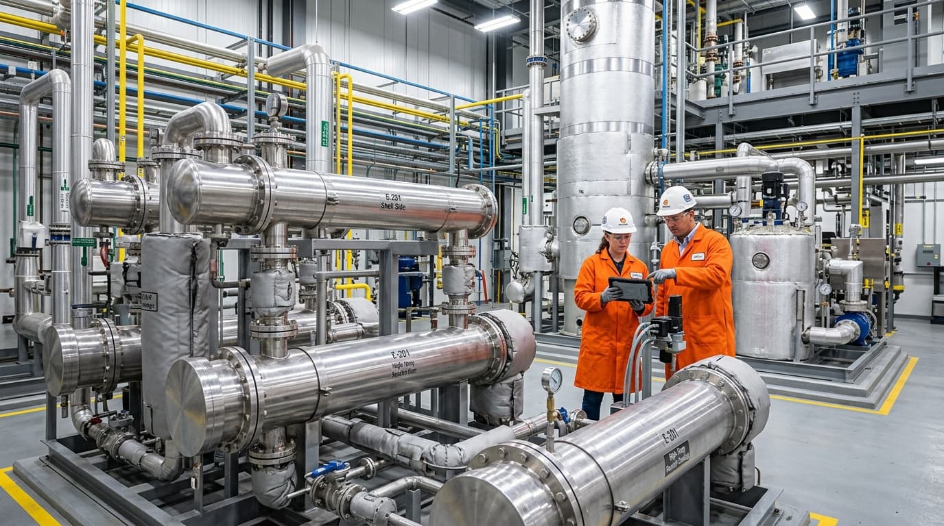
Recover waste heat and cut fuel costs with shell & tube or air-to-air exchangers engineered for continuous industrial duty.
Core Principles and Governing Equations
Thermal design calculations are fundamentally based on the principle of energy conservation and heat transfer mechanisms. Key equations underpin the entire design process:
Heat Transfer Rate (Q)
The fundamental equation for heat transfer in an exchanger is:
Q=UAΔTlmWhere:
- Q is the rate of heat exchange (W).
- U is the overall heat transfer coefficient (W/m²·K).
- A is the heat transfer area (m²).
- ΔTlm is the log mean temperature difference (K), representing the effective temperature driving force.
Overall Heat Transfer Coefficient (U)
The overall heat transfer coefficient (U) accounts for all resistances to heat transfer from one fluid to the other. These resistances include convection on the hot fluid side, conduction through the tube wall, and convection on the cold fluid side. Critically, it also incorporates fouling resistances (dirt coefficients) on both the shell and tube sides, which represent the thermal resistance of deposits that build up over time.
The calculation of U involves individual film coefficients (surface coefficients) for the tube-side and shell-side fluids, and the thermal conductivity of the tube material. Factors like fluid velocity, density, thermal conductivity, heat capacity, and viscosity significantly influence these film coefficients.
Log Mean Temperature Difference (LMTD)
The temperature difference between the hot and cold streams varies along the length of the heat exchanger. The Log Mean Temperature Difference (LMTD, or ΔTlm) provides an effective average temperature difference to represent the driving force for heat exchange in a pure counter-current setup:
ΔTlm=ln(ΔT1/ΔT2)ΔT1−ΔT2Where:
- ΔT1 is the temperature difference between the two fluid streams at one end of the exchanger (K or °C).
- ΔT2 is the temperature difference between the two fluid streams at the other end of the exchanger (K or °C).
For flow configurations that are not purely counter-current (such as multi-pass shell and tube exchangers), the calculated LMTD must be adjusted using a correction factor (F):
ΔTcorrected=FΔTlmThis F-factor, typically obtained from charts or analytical correlations, accounts for the departure from ideal counter-current flow and ensures that the effective temperature difference is accurately used in the heat transfer equation. It is widely advised to avoid arrangements where the F-factor is less than 0.75, with 0.85 being a more desirable minimum to prevent thermal pinch points.
Pressure Drop Considerations
Pressure drop is a critical design parameter, as excessive pressure drop leads to higher pumping costs and reduced thermal efficiency. The thermal design must ensure that pressure drops on both the tube side and shell side remain within acceptable limits.
- Tube-side pressure drop includes losses in the inlet/outlet nozzles, return covers, and friction within the tubes themselves. Factors like tube diameter, length, number of passes, and fluid velocity influence this.
- Shell-side pressure drop is affected by the shell diameter, baffle type, spacing, and arrangement, as well as fluid properties and velocity. Baffles are installed to enhance heat transfer by directing fluid flow and increasing velocity, but they also contribute to pressure drop.
The Thermodynamic Foundation: A Well-Insulated Shell-and-Tube Heat Exchanger
In analytical thermal calculations and academic problems, thermal engineers frequently assume a well-insulated shell-and-tube heat exchanger. This simplifying assumption means that any heat loss to the ambient surrounding environment is negligible (ambient heat loss, Qloss≈0).
Under this assumption, the steady-state energy balance dictates that the heat transfer rate released by the hot fluid must exactly equal the heat transfer rate absorbed by the cold fluid:
Q=m˙hCp,h(Th,in−Th,out)=m˙cCp,c(Tc,out−Tc,in)Where:
- m˙h and m˙c are the mass flow rates of the hot and cold fluids, respectively (kg/s).
- Cp,h and Cp,c are the specific heat capacities of the hot and cold fluids, respectively (J/kg·K).
- Th,in and Th,out are the inlet and outlet temperatures of the hot fluid (K or °C).
- Tc,in and Tc,out are the inlet and outlet temperatures of the cold fluid (K or °C).
For a well-insulated shell-and-tube heat exchanger, this fundamental energy balance is the first step in sizing or evaluation. It allows the designer to determine missing inlet or outlet temperatures before moving on to calculate the LMTD and the required surface area.
The ε-NTU Method and the 1-2 Shell and Tube Heat Exchanger Effectiveness Formula
When the fluid outlet temperatures are unknown, using the LMTD method requires tedious trial-and-error iterations. In these scenarios, the Effectiveness-NTU (ε-NTU) method is highly preferred. The effectiveness (ε) is defined as the ratio of the actual heat transfer rate to the maximum possible heat transfer rate that could be achieved in an infinite-area counter-current heat exchanger:
ε=QmaxQ=Cmin(Th,in−Tc,in)QWhere:
- Cmin is the smaller of the two heat capacity rates, calculated as C=m˙Cp (W/K).
The Number of Transfer Units (NTU) is a dimensionless parameter that measures the physical size of the heat exchanger:
NTU=CminUAThe heat capacity ratio is defined as:
Cr=CmaxCminFor a 1-2 shell and tube heat exchanger effectiveness formula (one shell pass and two or more even-numbered tube passes), the analytical relationship between effectiveness (ε), NTU, and Cr is governed by the following equation:
ε=21+Cr+1+Cr21−exp(−NTU1+Cr2)1+exp(−NTU1+Cr2)−1This formula allows designers to directly calculate heat exchanger effectiveness without knowing the outlet temperatures beforehand, making it an invaluable tool for rating and performance simulation.
How to Design a Shell and Tube Heat Exchanger
Designing a shell and tube heat exchanger is an iterative (trial-and-error) process that bridges thermal performance, fluid dynamics, and mechanical integrity. The diagram below illustrates the comprehensive workflow:
Detailed Steps in the Design and Sizing Process:
- Define Process Conditions and Purpose: Establish the heat exchanger's goal, including fluid flow rates, inlet/outlet temperatures, and desired heat duty (Q) for both hot and cold streams. Gather physical properties of the fluids, such as density, viscosity, thermal conductivity, and specific heat at relevant temperatures.
- Material Selection: Choose appropriate materials for the shell, tubes, and other components based on corrosion resistance, temperature, pressure requirements, and fluid characteristics. Common materials include carbon steel, stainless steel, copper alloys, and high-nickel alloys.
- Preliminary Sizing and Configuration: Make initial estimates for the overall heat transfer coefficient (U) based on standard industry reference tables for the specific fluid pair. Based on the calculated heat duty (Q) and LMTD, determine a preliminary heat transfer area: $$ A = \frac{Q}{U \Delta T_{lm}} $$ Select a preliminary configuration, including TEMA type (e.g., AES, BEM, AKT), number of shell and tube passes, tube diameter (e.g., 19.05 mm or 25.4 mm), tube length, and tube layout (triangular for high heat transfer density, square for mechanical cleaning access).
- Tube-side and Shell-side Flow Allocation: Decide which fluid flows through the tubes and which flows through the shell. General guidelines suggest placing corrosive, fouling, high-pressure, or high-temperature fluids on the tube side for easier physical cleaning and safer mechanical containment.
- Baffle Design: Choose baffle type (typically single segmental), spacing (typically 20% to 100% of the shell inner diameter), and cut (e.g., 20% to 25% for good heat transfer without excessive pressure drop). Baffles enhance heat transfer by inducing cross-flow turbulence and supporting the tube bundle to prevent vibration.
- Detailed Heat Transfer Coefficient Calculation: Calculate the individual heat transfer coefficients (h) for both sides:
- Tube-Side Coefficient (ht): Commonly computed using the Dittus-Boelter correlation for turbulent flow: $$ Nu_t = \frac{h_t d_i}{k} = 0.023 Re^{0.8} Pr^n $$ where n=0.4 for heating, n=0.3 for cooling, di is the tube inner diameter, and k is the fluid thermal conductivity.
- Shell-Side Coefficient (hs): Computed using Kern's method or the more rigorous Bell-Delaware method, which accounts for baffle bypass and leakage streams: $$ Nu_s = 0.36 Re_s^{0.55} Pr_s^{1/3} \left(\frac{\mu_b}{\mu_w}\right)^{0.14} $$ where Res is the shell-side Reynolds number, Prs is the shell-side Prandtl number, and μb/μw is the viscosity correction ratio from bulk fluid to tube wall temperature.
- LMTD and Correction Factor Calculation: Determine the LMTD based on the inlet and outlet temperatures. For multi-pass configurations, calculate the LMTD correction factor (F) using analytical equations or charts.
- Heat Transfer Area Verification: Recalculate the required heat transfer area (A) using the newly determined U and corrected LMTD. Compare this required area with the actual surface area provided by the selected tube bundle geometry. A safe design usually includes a 10% to 15% surface area margin.
- Pressure Drop Calculation: Calculate the pressure drop for both the shell side and tube side. If the computed pressure drop exceeds the maximum allowable process limit (typically 35 to 70 kPa for liquids), the flow path must be adjusted.
- Iteration and Optimisation: If the calculated heat transfer area does not match the required area, or if the pressure drops exceed allowable limits, revise the design. Adjust parameters such as tube length, shell diameter, baffle spacing, or the number of tube passes. This iterative loop is continued until a satisfactory, cost-optimised mechanical and thermal design is achieved.
Our ThermStack and EcoStream heat exchanger ranges deliver measurable energy savings across chemical, food, pharma, and power generation processes.
Sizing vs. Rating in Shell and Tube Heat Exchangers
In thermal design engineering, calculations are categorised into two distinct modes:
- Sizing (Design Mode): The process conditions (flow rates, temperatures, fluid properties) are completely specified, and the designer must calculate the physical dimensions of a brand-new heat exchanger (shell diameter, tube count, tube length, baffle spacing) to satisfy the heat duty.
- Rating (Simulation Mode): The physical geometry of an existing heat exchanger is fully known. The designer calculates whether this specific unit can perform a new thermal duty, or predicts the outlet temperatures and pressure drops under modified process conditions.
Tube-in-Tube Heat Exchanger Design: A Comparison
When selecting a heat exchanger configuration, engineers must contrast shell and tube heat exchangers with tube-in-tube (double-pipe) heat exchanger design. A tube-in-tube exchanger consists of one pipe concentrically positioned inside a larger pipe, with one fluid flowing through the inner pipe and the other through the annular space.
Understanding the operational and mathematical differences between these two designs is key to proper equipment selection:
- Flow Pattern: Tube-in-tube heat exchangers easily operate in true, 100% counter-current flow. As a result, the LMTD correction factor (F) is equal to 1.0, eliminating the risk of temperature crosses. Multi-pass shell and tube designs suffer from co-current portions, requiring correction factors.
- Fluid Velocity and Fouling: Tube-in-tube designs can maintain high fluid velocities even at very low flow rates, which minimises fouling. Shell and tube exchangers require a minimum velocity to prevent stagnant zones around the baffles where solids drop out of suspension.
- Calculations and Hydraulics: Tube-in-tube hydraulic design is much simpler, using the hydraulic diameter (De) of the annulus for Reynolds calculations: $$ D_e = D_{annulus, inner} - d_{tube, outer} $$ This allows for straightforward application of classic pipe flow equations without the complex bypass and leakage factors associated with shell-side baffle clearances.
- Economics and Scale: Tube-in-tube designs are highly cost-effective for small heat transfer duties (typically under 20 m² of surface area). However, for larger industrial duties, shell and tube heat exchangers are much more compact and economical per unit of surface area due to the nesting of hundreds of tubes in a single shell.
Factors Influencing Thermal Design
Several factors significantly influence the thermal design and performance of shell and tube heat exchangers:
- Fluid Properties: Viscosity, density, specific heat, and thermal conductivity of both fluids directly impact heat transfer coefficients and pressure drops. High-viscosity fluids are typically routed to the shell side to facilitate better turbulence around the baffles.
- Fouling: The accumulation of deposits on heat transfer surfaces reduces the overall heat transfer coefficient and increases pressure drop. Design must account for fouling factors and consider maintenance ease.
- Flow Arrangements: The number of shell and tube passes (e.g., 1-2, 2-4) affects the LMTD correction factor and the overall efficiency. Counter-current flow is generally more efficient.
- Baffle Design: Baffle type, spacing, and cut profoundly influence shell-side velocity, turbulence, and pressure drop, thereby impacting the shell-side heat transfer coefficient.
- Tube Layout and Geometry: Tube diameter, length, and pitch (triangular or square) affect heat transfer area, fluid velocities, and pressure drop.
- Thermal Expansion: Differences in thermal expansion between the shell and tubes must be accommodated, especially in fixed tube-sheet designs. Floating head and U-tube designs offer solutions to this challenge.
Software and Tools for Thermal Design
Given the iterative and complex nature of shell and tube heat exchanger thermal design, specialised software tools are widely used by engineers. These programmes automate calculations, enable rapid iteration, and facilitate optimisation. Examples include commercial software solutions like HTRI (Heat Transfer Research, Inc.), Aspen Exchanger Design and Rating (EDR), AHED, and UNILAB UNISUITE SHELL. These platforms offer robust features for design, rating, selection, and detailed hydraulic analysis, including rigorous multi-dimensional pressure drop and vibration analysis. These tools generate optimal mechanical and thermal designs quickly, minimising design margins while strictly obeying allowable pressure drop limits.
Conclusion
Thermal design calculations for shell and tube heat exchangers are a fundamental aspect of chemical and mechanical engineering, essential for the efficient and safe operation of countless industrial processes. By understanding the core principles, governing equations, and iterative design steps, engineers can effectively balance heat transfer requirements with practical constraints. The continued development of advanced simulation software further empowers designers to create optimised, high-performance heat exchangers that meet the dynamic demands of modern industrial applications.
