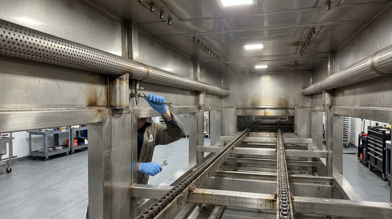
Improving Oven Performance Through Precise Turbulence Airflow Modelling
An industrial processing equipment manufacturer recently sought a technical evaluation of their multi-module oven design, which was failing to maintain consistent thermal output across its seven internal processing zones. The facility, which relies on precise convective heat transfer to ensure product quality, was experiencing non-uniform airflow across the product belt, leading to potential inconsistencies in final product texture and moisture content.
The managing director and the technical manager identified that previous attempts to balance the airflow via standard mechanical adjustments had not yielded the desired consistency. Consequently, EnerTherm Engineering was engaged to conduct a comprehensive CFD analysis to model the oven modules and determine the root cause of the airflow disparities.
Diagnostic Approach: Modelling Boundary Conditions
The first phase of the engagement required a rigorous evaluation of the existing system configuration. The team focused on the interaction between a specific fan model used for turbulence generation and the associated ductwork. This involved simulating the fan curve into the turbulence ducting inlet and extraction ports to verify actual flowrates compared against the design specifications.
Our engineers mapped the turbulence ducting to identify pressure drop and volumetric flow variation across the seven distinct oven modules. The initial data revealed a significant discrepancy: the central ducts were receiving a disproportionate amount of airflow, while ducts 4 and 5 - those closest to the fan inlet - suffered from reduced air volume. This created a highly irregular airflow distribution, which directly impacted the oven module's ability to maintain a stable thermal profile.
We established the following baseline parameters for the study:
- Extraction Flow: 0.86 m³/s
- Inlet Flow: 0.83 m³/s
- System Static Pressure: 101325 Pa
Identifying Systemic Constraints
The CFD analysis highlighted that the pressure drop from the turbulence air in/out nozzles was excessively high. Further investigation confirmed that the specific fan model installed was incapable of achieving the required design turbulence air flow. At the design flowrate, the air across the product band was not uniformly distributed, and the distribution of turbulence air inlet and outlet velocities varied significantly across the seven oven modules.
The CFD model demonstrated that the fan was operating outside its ideal performance envelope, resulting in negligible air velocity across large sections of the oven module and extremely high, inconsistent velocities at the inlet nozzles.
In a secondary simulation, we evaluated the pressure drop at the fan's maximum duty point. With the sides of the oven open to environmental pressure, the volumetric flowrate dropped to just 0.0015 m³/s, proving that the existing fan configuration could not compensate for the high system resistance. It became clear that modifying the existing fan parameters alone would not resolve the issue without addressing the duct geometry and nozzle configuration.
Optimising Duct Geometry
To address the uneven airflow, EnerTherm Engineering proposed a redesign of the internal distribution system. We utilised process modelling to run two distinct scenarios, aiming to reduce system resistance while improving distribution.
Simulation 1: Minimising System Resistance
The first simulation focused on lowering the overall pressure drop by increasing the oven module distribution duct widths to match the width of the main turbulence duct. While this successfully reduced the pressure drop, the CFD results indicated that it did not achieve uniform airflow distribution. The flow rates remained skewed towards the central sections of the oven.
Simulation 2: Achieving Uniformity
The second simulation involved varying the oven module distribution duct widths across the entire length of the system. By modifying the duct openings, we were able to redistribute the air mass flow rate to compensate for the duct geometry limitations. This approach targeted an even distribution of air mass across all seven oven modules.
| Module | Sim 1 (Uniform Width) Mass Flow (kg/s) | Sim 2 (Optimised) Mass Flow (kg/s) |
|---|---|---|
| Duct 1 | 0.1334 | 0.0956 |
| Duct 2 | 0.0918 | 0.0930 |
| Duct 3 | 0.0719 | 0.1014 |
| Duct 4 | 0.0600 | 0.0842 |
| Duct 5 | 0.0638 | 0.1099 |
| Duct 6 | 0.1178 | 0.1033 |
| Duct 7 | 0.2750 | 0.1094 |
| Average DP (Pa) | 10.35 | 87.55 |
Measurable Results and Engineering Recommendations
The implementation of the variable duct width design, as validated by our CFD model, delivered an 87% increase in flow uniformity across the seven oven modules. The mass flow rate was brought within a 5% variance across all modules, a significant improvement over the initial state.
Based on these findings, EnerTherm Engineering provided the client with a strategic roadmap for implementation and further performance enhancement:
- CFD Validation: The model results should be validated by measuring physical air velocity and static pressure at key points within a running oven module to confirm the simulated accuracy.
- Nozzle Redesign: Following the duct optimisation, we recommended a redesign of the inlet nozzles to further refine the airflow profile across the product band.
- Fan System Review: Given that the current specific fan model struggled to meet design flow requirements, we advised evaluating alternative fan units or reconfiguring the use of extraction and turbulence fans to improve overall system efficiency.
- Efficiency Analysis: The client is now able to assess the efficiency of the oven module with varied turbulence airflow velocities, using our model as a guide to determine the ideal operating point for different product lines.
This engagement demonstrated that small, calculated changes to duct geometry, informed by detailed process modelling, can yield substantial improvements in thermal efficiency and process consistency.

Managing Director — EnerTherm Engineering
Dr. François Pierrel is Managing Director of EnerTherm Engineering with over two decades of expertise in thermal design, heat transfer, and industrial energy optimisation. He holds a PhD in Heat Transfer from Cranfield University and a Post-Doctorate from Heriot-Watt University.
