Optimising Coating Manifold Flow Distribution via Iterative CFD Simulation
Project Overview
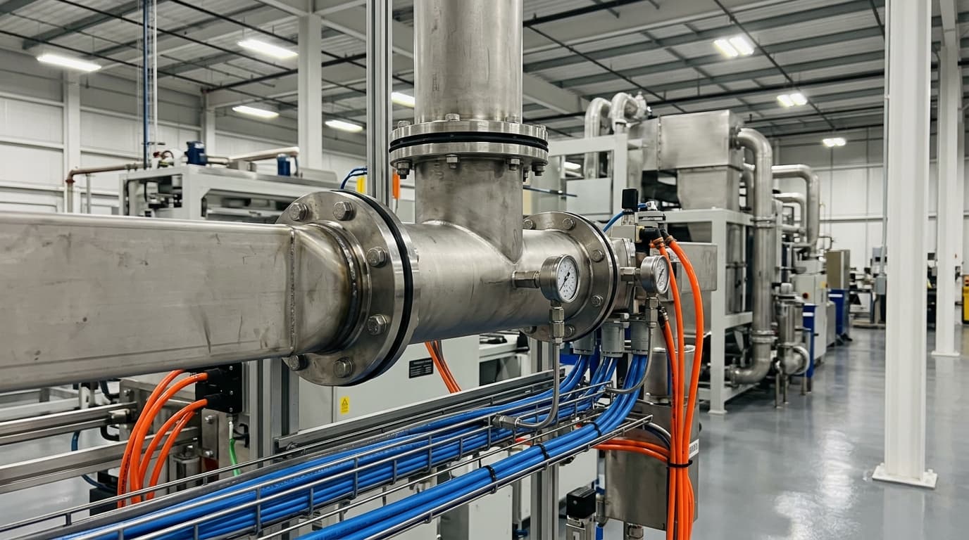
A manufacturing client company operating a high-volume coating line required an evaluation of a T-shape duct manifold design intended to replace an existing three-valve distribution system. The facility had been experiencing inconsistent coating mass flow across a 3 mm slot, which compromised product quality. To determine the feasibility and optimal configuration of the proposed design before physical implementation, a specialised engineering consultancy was engaged to conduct a series of CFD simulations.
The objective was to achieve uniform material distribution across the length of the coating slot. Previous attempts using a three-valve system had proven difficult to balance effectively, leading to variable coating thickness. The transition to a fixed-geometry T-shape duct aimed to simplify the process and improve consistency. The engineering team was tasked with parametrically modelling the geometry to identify the slot configuration that would minimise mass flow deviation.
Methodology and Computational Approach
The engineering team utilised advanced simulation software to build a parametric model of the manifold. This allowed for variations in the slot aperture from the centre to the end of the duct. To solve the fluid flow, pressure, and temperature interactions, the inner volume of the pipework was discretised into a mesh. Each tetrahedral and cubic element within this mesh served as a nodal point for solving the Navier-Stokes equations.
| Parameter | Value/Assumption |
|---|---|
| Material | A proprietary material reference |
| Inlet Mass Flow | 0.006 kg/s |
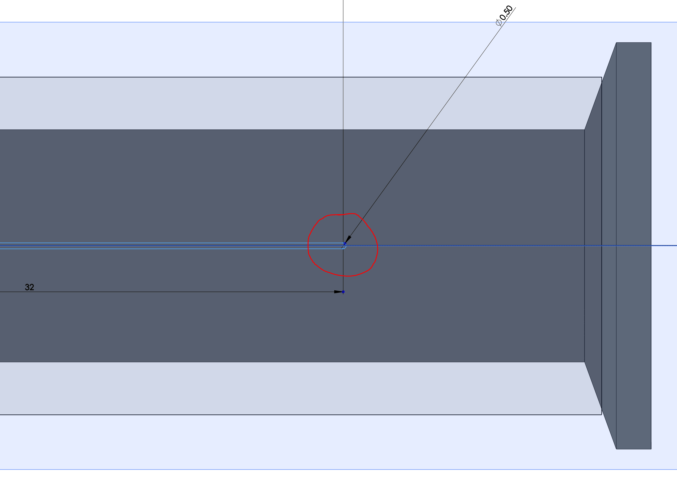
| Slot Width | 3 mm |
| Outlet Configuration | 31 individual outlets modelled |
The simulation mesh was refined across six levels to balance computational time with accuracy. Boundary conditions were established by setting the inlet mass flow and defining the outlets as atmospheric. A gravitational vector was applied to ensure the model accurately represented the vertical orientation of the coating curtain. For every design iteration involving changes to the slot aperture, the mesh was recalculated to maintain high-fidelity results.
Analysis of Initial Findings
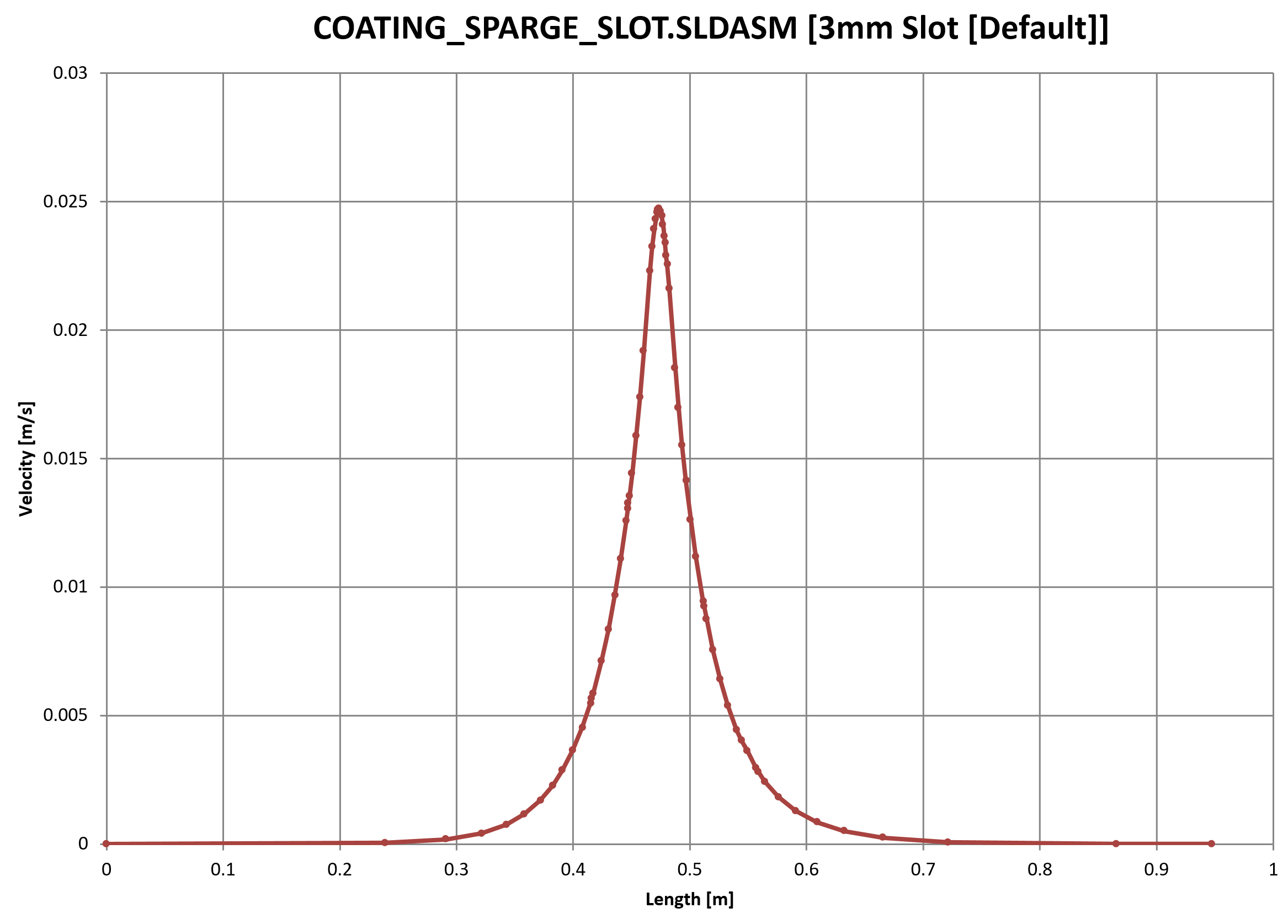
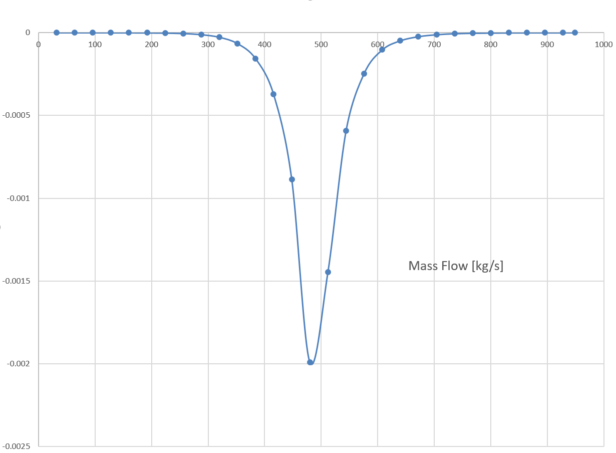
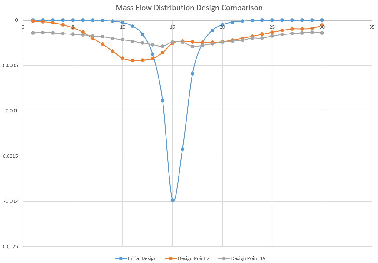
The baseline simulation, using a uniform 3 mm slot, revealed significant challenges in flow distribution. Initial analysis showed peak velocity at the centre of the manifold, with flow velocity approaching zero at the extremities. The mass flow profile mirrored the velocity distribution, confirming that the initial design would result in uneven coating.
The initial simulation of the uniform 3 mm slot resulted in a standard deviation of mass flow of 0.000418 kg/s. While this may appear low in absolute terms, the profile indicated a stagnant layer effect that rendered the design unsuitable for consistent coating applications.
Furthermore, the pressure drop across the manifold was calculated at 350 mbar. This was noted as being 10 times higher than the previous three-valve manifold design, representing a significant trade-off in system efficiency that required careful consideration during the optimisation phase.
Iterative Optimisation Process
To improve flow uniformity, the project lead implemented a parametric optimisation strategy. The team focused on two key variables: the centre slot aperture and the outer slot radius. This involved running multiple design iterations, with each simulation taking approximately 40 minutes to solve.
Centre Slot Adjustments
The first phase of optimisation involved varying the centre slot half-width from 0.2 mm to 1.5 mm in 10 distinct increments. The design iteration designated as Design 2, which featured a centre slot half-width of 0.344 mm, demonstrated the flattest mass flow distribution of the initial series.
Outer Radius Optimisation
While Design 2 reduced mass flow variability by 72% compared to the original design, the team determined that further improvements were necessary, particularly regarding the near-zero velocity at the outer edges of the tube. Consequently, a secondary optimisation model was developed to vary the outer slot radius between 0.5 mm and 1.5 mm.
The team created 36 distinct design combinations, including configurations with asymmetrical radii on either side of the manifold. By systematically testing these combinations, the team identified Design 19 as the optimal configuration.
Final Results and Conclusions
The computational modelling programme successfully identified a geometric configuration that provided a significantly more uniform coating curtain. The comparative performance of the designs is summarised below:
- Initial Design: Established baseline variability.
- Design 2: Improved mass flow variability by 72% through centre slot adjustment.
- Design 19: Improved mass flow variability by 89% through a combination of centre slot adjustment and variable outer radius tuning.
While the optimisation process significantly improved uniformity, it highlighted a necessary engineering trade-off. By reducing the slot apertures to achieve this level of balance, the pressure drop across the manifold system increased from 350 mbar to 540 mbar. This represents a substantial increase in system resistance compared to the original three-valve manifold.
The engineering consultancy concluded that while the current T-shape design, specifically the geometry represented by Design 19, offers a marked improvement over the baseline, it is not the ideal configuration for long-term distribution efficiency. The team recommended that for future system upgrades, a transition to a triangular-shaped duct profile would offer a more robust solution for achieving perfectly uniform flow distribution without the significant pressure drop penalties associated with the current manifold geometry.

Managing Director — EnerTherm Engineering
Dr. François Pierrel is Managing Director of EnerTherm Engineering with over two decades of expertise in thermal design, heat transfer, and industrial energy optimisation. He holds a PhD in Heat Transfer from Cranfield University and a Post-Doctorate from Heriot-Watt University.
