Optimising Anaerobic Digester Insulation to Meet Stringent Thermal Asset Standards
Project Context
A biogas production facility operating eight primary anaerobic digesters was failing to meet its internal asset standards for thermal efficiency. Operational assessments indicated that the systems were experiencing heat losses of 1°C per 24 hours, exceeding the target threshold of 0.5°C per 24 hours at an external ambient temperature of -10°C. The loss was primarily attributed to the historical removal of roof insulation, while the walls faced ongoing challenges regarding long-term thermal retention.
The facility was operating at internal temperatures between 38°C and 42°C. A utility service provider engaged a thermal engineering consultancy to determine if wall insulation could be maximised to compensate for the missing roof protection, or if a hybrid approach was required to bring the digesters back into compliance. The project required balancing structural loading limits, safe access for instrumentation, and the technical requirements of complex flanged connections.
Technical Challenge
The primary constraint involved the practical difficulty of reinstating roof insulation. The roof area featured numerous instruments and flanged connections, complicating the installation of standard materials. Furthermore, any proposed solution needed to satisfy strict structural loading constraints while ensuring the system could maintain the desired temperature profile. The project lead and the project engineer were tasked with creating a robust thermal model to determine if the 0.5°C/24hr heat loss limit could be achieved through wall insulation alone, or if partial roof coverage was unavoidable.
The project stakeholder provided the digester design documentation and the insulation material specification document to establish baseline parameters. The consultancy proceeded to develop a thermal model using CFD and FEA to simulate heat transfer under realistic environmental conditions.
Methodology and Modelling
To ensure accuracy, the team established a range of boundary conditions based on historical data. The simulation focused on the external heat transfer coefficient, influenced by an average wind speed of 4.27 m/s (equivalent to 8.3 knots) and an ambient air temperature of -10°C. The concrete thermal conductivity was modelled across a range of 0.5 to 2.5 W/(m·K) to account for potential variations in construction materials.
Theoretical Fluid Dynamics
The engineering team first calculated the Reynolds number to understand the flow characteristics around the 15-metre diameter digester. With a calculated Nusselt number of 17,317, the team derived an external heat transfer coefficient of 30.29 W/m²·K. This value served as a baseline for the subsequent CFD simulations.
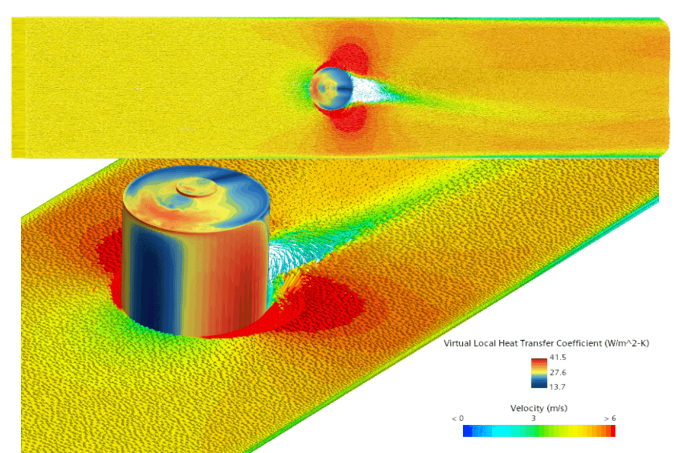
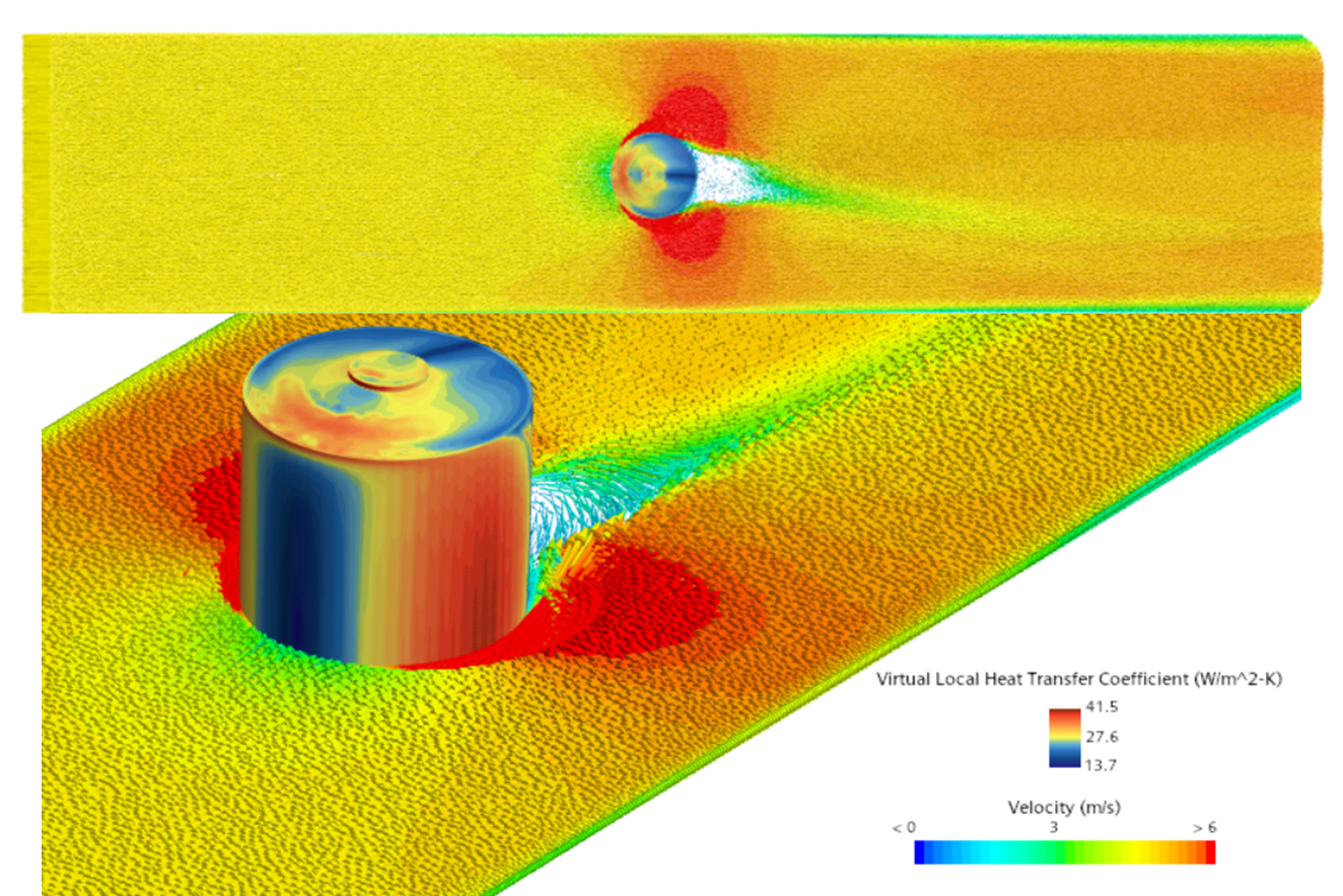
The CFD modelling provided a detailed assessment of the airflow across both cylindrical wall surfaces and the roof. The analysis indicated that the front surfaces of both the wall and the roof experienced higher average heat transfer coefficients compared to the back surfaces, necessitating a more robust approach to insulation thickness to ensure uniform thermal performance across the entire structure.
Results and Findings
The thermal modelling confirmed that while wall insulation was a critical factor, the impact of the roof gas temperature—modelled at 30°C—significantly influenced total heat loss. The team utilised an in-house thermal calculator to determine the insulation requirements based on variable concrete thermal conductivities.
Wall Insulation Requirements
The analysis demonstrated that to achieve the required 0.5°C/24hr limit, insulation thickness must scale in proportion to the thermal conductivity of the concrete structure. The findings are summarised in the table below:
| Ambient Heat Transfer Coefficient (W/m²·K) | Concrete Thermal Conductivity (W/m·K) | Required Insulation Thickness (mm) |
|---|---|---|
| 30 | 1.0 | 120 |
| 30 | 1.7 | 150 |
| 30 | 2.5 | 150 |
Roof Insulation Assessment
The simulations regarding roof heat loss yielded clear metrics for remedial action. With the internal gas temperature assumed to be 30°C and an external heat transfer coefficient of 28 W/m²·K, the required roof insulation thickness was calculated at 110 mm. The analysis further indicated that if operational conditions allowed for a lower internal gas temperature of 20°C, the necessary insulation thickness could be reduced to 85 mm.
Conclusion
The thermal recovery project provided the data necessary to move forward with site remediation. The study concluded that relying solely on wall insulation would not satisfy the asset standards for the digesters. The team recommended a tiered approach to insulation: applying 120 mm to 150 mm of insulation to the walls, depending on the specific thermal conductivity of the concrete, and incorporating 85 mm to 110 mm of insulation on the roof to address the convective losses identified in the gas headspace.
By utilising the combination of CFD and empirical thermal calculations, the consultancy delivered a verified pathway to compliance. This approach allows the facility to optimise energy retention while maintaining structural integrity and operational access to the digester instrumentation.

Managing Director — EnerTherm Engineering
Dr. François Pierrel is Managing Director of EnerTherm Engineering with over two decades of expertise in thermal design, heat transfer, and industrial energy optimisation. He holds a PhD in Heat Transfer from Cranfield University and a Post-Doctorate from Heriot-Watt University.
