Keeping a Firefighting Stair Clear: Industrial Smoke Shaft Simulation
A multi-storey industrial plant building in the northern UK had a firefighting stair, a ventilated lobby at each level and a smoke shaft serving those lobbies. The shaft had been built smaller than required by BS 9999, the British Standard for fire safety in buildings. The owner of the industrial plant asked EnerTherm Engineering to establish whether a fan at the head of the existing shaft could provide suitable smoke control and what evidence the approving authority would require.
The issue concerned more than the shaft dimensions alone. The system needed to keep the firefighting stair clear while removing smoke from the affected lobby, without creating door-operability problems or transferring smoke to other parts of the building. As the shaft served an operational plant, the assessment focused on conditions relevant to firefighting access and smoke movement.
Starting with the building as it existed
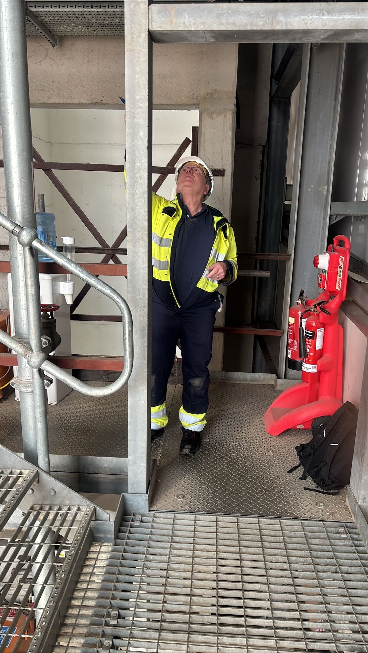
EnerTherm Engineering began with a detailed site survey rather than relying on the available drawings. The team measured the shaft, its discharge, every opening connecting it to the lobbies and the relevant doors. This work identified differences between the design information and the constructed building, including a change in shaft size part-way up the building.
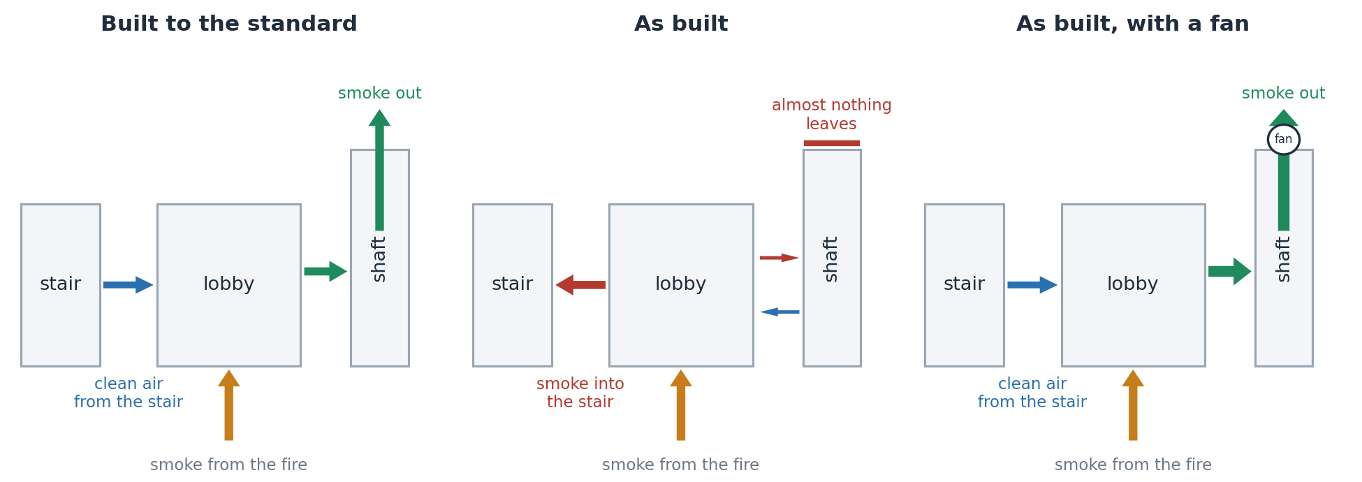
The survey also identified an important feature of the openings into the shaft. Although they were larger than the standard required, they were configured as full-height slots. This geometry allowed smoke to leave through the upper part of an opening while drawing replacement air back through the lower part. The opening area alone therefore did not describe how the shaft would perform.
The shaft moved smoke in and out through the same openings. The issue was the shape of those openings, rather than their overall area.
Defining the right questions before modelling
No design fire had previously been defined for the building. EnerTherm Engineering carried out screening calculations for potential fire locations and compared them on a consistent basis to identify the cases requiring detailed assessment. This gave the model a clear and proportionate technical basis.
The team agreed the proposed scenarios, assessment method and acceptance criteria with the approving authority before completing the modelling. Establishing this route early ensured that the final report addressed the questions that would inform the approval decision, rather than producing results that required further analysis later.
EnerTherm Engineering then used the open-source Fire Dynamics Simulator (FDS) to create three-dimensional smoke movement and ventilation models. Python supported model development, result extraction and the preparation of clear visual outputs. Each case applied the same conditions, with the smoke shaft arrangement as the controlled difference.
| Arrangement assessed | Purpose of the comparison |
|---|---|
| Shaft built to the standard | Established a reference arrangement for smoke movement and stair protection. |
| Shaft as built | Tested the performance of the installed shaft and its full-height openings. |
| As-built shaft with smoke extract fan | Tested whether mechanical extraction could improve smoke removal while protecting the stair. |
Simulation exposed the weakness in the as-built shaft
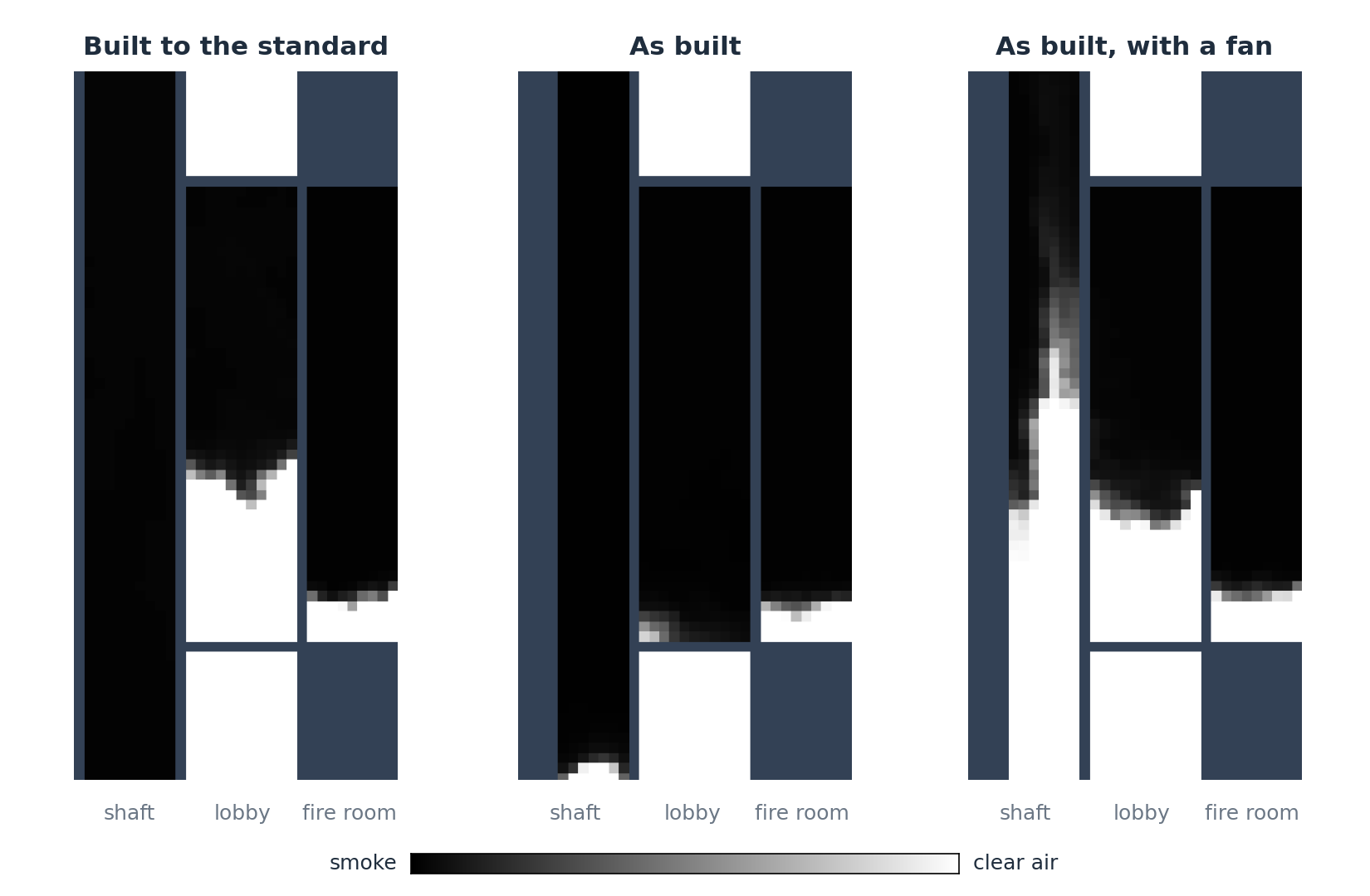
The as-built shaft did not clear smoke effectively. Smoke travelled in and out through the same lobby openings, which limited the shaft's ability to establish a reliable upward smoke path. Most of the smoke entered the firefighting stair, reducing the protection that the lobby and shaft arrangement was intended to provide.
The smoke-contour comparison illustrates the difference between the three arrangements. In the standard shaft case, smoke follows the intended extract route. In the as-built case, smoke remains within the lobby and shaft region rather than clearing effectively. With a fan added to the as-built shaft, smoke is drawn upwards through the shaft and the lobby is substantially clearer.
A companion schematic of the smoke and air routes makes the underlying mechanism easier to see. The as-built full-height slot allows opposing flows through one opening: smoke leaves at high level while air enters below. The fan-assisted arrangement establishes extraction through the shaft and directs air from the stair towards the lobby, helping to hold smoke back from the stair enclosure.
Testing the proposed fix revealed a second design issue
The fan-assisted shaft performed better than the shaft built to the standard. It removed more smoke, kept the firefighting stair clear and produced a far clearer lobby than the as-built arrangement. The simulation therefore confirmed that mechanical smoke extraction could address the primary ventilation problem.
It also identified a consequence that would have been easy to miss during a dimensional review. With a fan operating and no dedicated air inlet, the pressure difference across the lobby door would hold it shut with a force above the recommended opening limit. A system that cleared smoke but prevented practical firefighter access would not meet the operational requirement.
EnerTherm Engineering assessed a dedicated air inlet to the lobby as part of the same design development. This replacement-air path reduced the door opening force to around the recommended limit while maintaining the smoke-control benefits of the fan. The team found and resolved this interaction in the model, before installation work began.
A practical smoke-control package for approval
The resulting design is provisional pending final sign-off. It comprises a smoke extract fan at the head of the shaft, a dedicated lobby air inlet, dampers arranged so that only the affected level opens, and a firefighter's switch. The selected fan will confirm the final fan duty.
EnerTherm Engineering provided the technical record behind the assessment alongside a concise overview for decision makers. The report set out the site-survey findings, the agreed modelling approach, the comparison of arrangements and the evidence supporting the proposed controls. This gave the owner a defined basis for discussion with the approving authority.
What industrial plant owners can take from this study
Ventilation and smoke-control systems can depart from their intended behaviour when construction details differ from drawings, when openings are reshaped, or when new mechanical plant changes the pressure balance. A check against a standard can identify a dimensional departure, but it may not show how smoke and replacement air will move through a real building.
Thermal Design Simulation allows plant owners, operators, designers and contractors to test a proposed change before committing to site work. It can compare an existing arrangement with alternative designs, show where smoke is likely to travel, assess the effect of replacement air and identify operational constraints such as door opening force.
In this case, the outcome was clear: the as-built shaft allowed most smoke into the firefighting stair, while the fan, air inlet and level-control dampers created a route that cleared more smoke than the standard reference arrangement, kept the stair clear and returned door opening force to around the recommended limit. Industrial owners facing a ventilation or smoke-control concern can contact EnerTherm Engineering for a short review of their situation and whether simulation can provide the evidence for a practical fix.

Managing Director — EnerTherm Engineering
Dr. François Pierrel is Managing Director of EnerTherm Engineering with over two decades of expertise in thermal design, heat transfer, and industrial energy optimisation. He holds a PhD in Heat Transfer from Cranfield University and a Post-Doctorate from Heriot-Watt University.
