Optimising Burner Safety and Reliability: Commissioning a Complex Gas Train
The Challenge: Critical Snagging in Burner Infrastructure
A large-scale industrial processing facility initiated a project to install and commission a new dryer system, incorporating a sophisticated burner assembly. During the initial commissioning phase, a specialized engineering consultancy conducted a comprehensive site assessment of the burner gas train and auxiliary fuel infrastructure. The assessment identified several critical non-conformances that threatened both the operational integrity and the safety of the plant.
The primary issues stemmed from a lack of integration between the component layout and the site specific spatial constraints. The initial installation lacked essential safety features, including proper local gas isolation, downstream pressure relief venting, and structural vibration mitigation. Furthermore, the existing valve configuration was unsuitable for the available footprint, creating an immediate bottleneck for the mechanical installation team.
The facility required a rapid, engineered solution to rectify these deficiencies and ensure that the burner system could be commissioned safely without impacting production schedules. The project lead was tasked with overseeing the technical redesign, collaborating with the burner equipment manufacturer and the lead mechanical contractor to implement a compliant solution.
Engineering a Compliant Gas Train Design
The initial review of the gas train revealed a significant oversight: the absence of a pressure relief system downstream of the pressure regulator. Given that site policy prohibited venting directly to the roof, the team had to design a bespoke relief path that safely discharged gases to the exterior of the building while ensuring that no moisture ingress occurred within the relief pipework.
A second, equally pressing concern involved the protection of the gas train components from mechanical vibration. High-frequency vibration, common in industrial dryer applications, posed a risk of loosening fittings and compromising seal integrity over time. To address this, the project team coordinated with a burner equipment manufacturer to specify and integrate a flexible connection—a flexi-pipe—directly into the gas train assembly. This measure was critical to maintaining the longevity of the manifold and preventing fatigue-related leaks.
The design process required a reconfiguration of the gas train to fit the available space on the right-hand side of the dryer. This necessitated modifications to the access door frame, managed by the installation coordinator. By creating a custom layout, the team ensured that the isolation valve remained accessible for emergency shutdown procedures, a vital requirement for operator safety.
Resolving Mechanical Fabrication Constraints
The project faced an additional hurdle regarding valve selection. The initial gate valve supplied by the lead mechanical contractor was physically too large for the allocated installation space. The team conducted a rapid re-evaluation of the flow requirements and clearance constraints, concluding that a butterfly valve would provide the necessary isolation capability while fitting within the reduced envelope. The lead mechanical contractor was then authorised to fabricate custom pipework reducers to facilitate the transition between the existing line size and the new valve assembly.
The procurement of the necessary components was streamlined by referencing specific technical requirements provided by the burner equipment manufacturer. The order included:
| Component Description | Generic Part Number | Quantity |
|---|---|---|
| Parts for mounting manometer | a generic part number | 1 |
| Test burner (short version) | a generic part number | 1 |
| Pressure gauge (0 to 60 mbar) | a generic part number | 1 |
By centralising the procurement of these parts, the installation coordinator ensured that all specified components arrived on-site within a 2-week window, allowing the mechanical fabrication company to complete the assembly without further delays.
Diesel Fuel Line Integration and Safety Interlocks
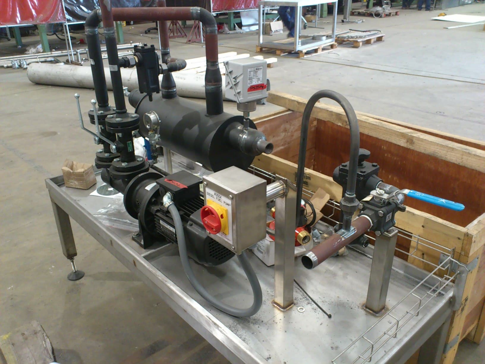
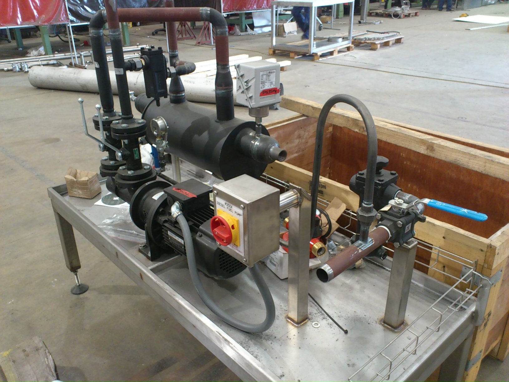
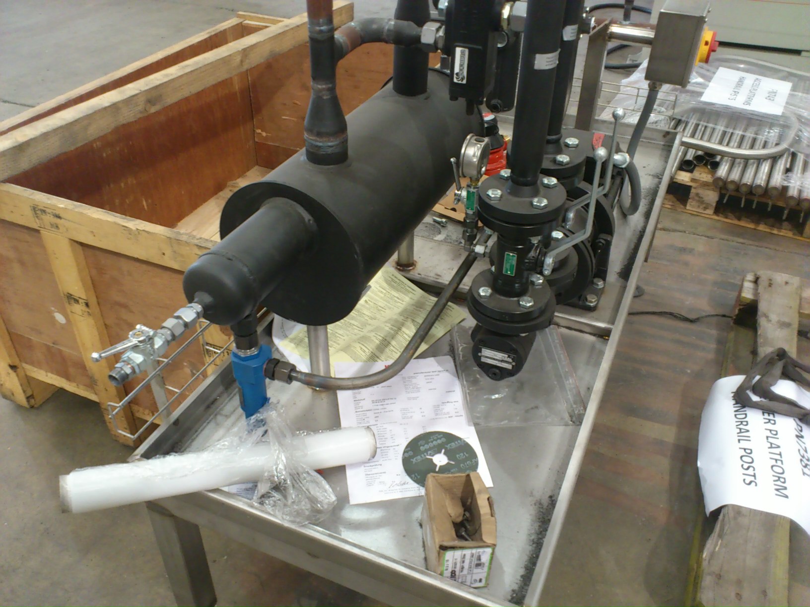
In addition to the gas train, the burner system utilised a diesel fuel supply that required an equally robust approach to safety. The system design necessitated a clear interlock between the oil ball valves and the burner control system. The team installed micro-switches on the linked oil supply and return valves to ensure that if the valves were closed, the burner would be electronically disabled to prevent misfires or fuel spillage.
The installation of the package air separator and fuel valves was completed as close to the burner as physically possible. This configuration minimised the length of the final flexible hose connections, reducing the risk of hose damage from trailing on the floor or contact with sharp machinery. During the final inspection, the team decided against installing isolation valves directly onto the pump housing, as the pump flanges were not standard-round. Instead, the team positioned isolation valves as close as possible to the pump inlet and outlet, ensuring maintenance could be performed safely without compromising the pump structural connection.
Following the adjustment of the diesel pump skid legs—a modification that optimised the fuel supply pressure to the pump inlet—the fuel system was fully commissioned. The total integration of gas and diesel safety systems ensured that the burner operated within the stringent safety parameters required by the facility.
Outcomes and Operational Status
Through a disciplined approach to site snagging, redesign, and collaborative procurement, the specialized engineering consultancy successfully remediated the burner installation. The final system achieved full compliance with site safety policies, including:
- The successful installation of a vibration-dampened gas train, ensuring component longevity.
- The implementation of a safe, non-roof-vented pressure relief system.
- The integration of safety interlocks on the diesel fuel line, preventing unauthorized or unsafe burner firing.
- Optimised layout design that maintained emergency access while respecting spatial limitations.
By addressing these mechanical and regulatory non-conformances, the project team prevented potential downtime and ensured the facility could proceed with the commissioning of the dryer unit with confidence in the reliability and safety of the burner assembly.

Managing Director — EnerTherm Engineering
Dr. François Pierrel is Managing Director of EnerTherm Engineering with over two decades of expertise in thermal design, heat transfer, and industrial energy optimisation. He holds a PhD in Heat Transfer from Cranfield University and a Post-Doctorate from Heriot-Watt University.
