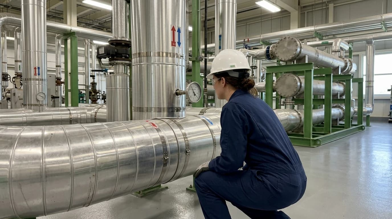
Pinch Analysis Cuts Chemical Plant Heat Waste by 15-25%
How pinch analysis heat integration cuts plant fuel use by 15-25% for ESOS compliance.
Pinch Analysis is a systematic thermodynamic engineering methodology used in sustainable industrial thermal management to design optimal heat exchanger networks by calculating thermodynamically feasible energy targets and minimising utility consumption. By identifying the absolute thermodynamic limits of energy recovery within a chemical manufacturing facility, this structured engineering approach regularly reduces hot and cold utility demands by 15 to 25 per cent.
Chemical plants rely heavily on high-temperature thermal processes, which often discharge substantial waste heat to the atmosphere or local water bodies. Rather than evaluating individual unit operations in isolation, process engineers use Pinch Analysis to analyse the entire facility as an integrated system, matching waste heat sources with heating demands to maximise efficiency and decrease fossil fuel reliance.
Understanding the Thermodynamics of Process Heat Integration

Defining the Thermodynamic Pinch Point
Historically, engineering teams optimised chemical plants by focusing on individual components, such as adjusting a boiler's air-to-fuel ratio or upgrading a specific distillation column condenser. This unit-by-unit approach fails to capture the systemic energy interactions within a facility. Chemical manufacturing processes contain numerous hot streams requiring cooling and cold streams requiring heating. Traditional heat integration methods often match these streams arbitrarily, resulting in concurrent, unnecessary fuel combustion and cooling-tower load.
Pinch Analysis addresses this inefficiency by identifying the thermodynamic limit of heat recovery within a system. The pinch point is a specific temperature threshold that divides the process into two distinct thermodynamic regions. Above the pinch, the process has a net heat deficit and requires external hot utility. Below the pinch, the process has a net heat surplus and requires external cold utility.
The Fundamental Rules of Pinch Technology
To eliminate thermal waste, engineers must strictly adhere to three fundamental rules derived from the second law of thermodynamics:
- Do not transfer heat across the pinch point.
- Do not use external cold utility above the pinch point.
- Do not use external hot utility below the pinch point.
If a plant design transfers heat across the pinch point, it simultaneously increases the hot utility requirement above the pinch and the cold utility requirement below the pinch by that exact amount. Chemical plants that ignore these rules typically operate with significant energy surpluses. Applying Pinch Analysis allows engineers to identify these violations and redesign the network to recover this wasted heat, directly lowering operational costs and carbon emissions.

Pinch analysis identifies the thermodynamic minimum energy requirement of your process — then designs the heat exchanger network to achieve it.
Mathematical Principles of Heat Exchanger Network Design Optimisation
The Minimum Temperature Approach
At the centre of any pinch study is the minimum temperature approach, denoted as ΔTmin. This parameter represents the smallest temperature difference permitted between a hot stream and a cold stream at any point within a heat exchanger. Choosing the value of ΔTmin dictates both the thermodynamic efficiency and the capital cost of the heat exchanger network.
A smaller ΔTmin increases the overlapping region between the hot and cold composite curves, reducing the requirement for external hot and cold utilities. However, as the temperature difference between the streams decreases, the driving force for heat transfer also decreases, which necessitates a larger physical heat transfer area.
Heat Transfer Area and Capital Cost Trade-Offs
Engineers quantify the physical size of the heat exchange equipment using the fundamental heat transfer relationship:
Q=U⋅A⋅ΔTlmWhere:
- Q is the heat transfer rate in kilowatts (kW)
- U is the overall heat transfer coefficient in kilowatts per square metre-degree Celsius (kW/m²·°C)
- A is the required heat transfer area in square metres (m²)
- ΔTlm is the logarithmic mean temperature difference in degrees Celsius (°C)
When designers decrease ΔTmin, the logarithmic mean temperature difference (ΔTlm) across the network decreases, forcing the required heat transfer area (A) to expand to transfer the same rate of heat (Q). The relationship between energy savings and capital expenditure requires careful optimisation, as shown below:
| Parameter change | Impact on utility consumption (OPEX) | Impact on heat exchanger size (CAPEX) |
|---|---|---|
| Decreasing ΔTmin | Decreases hot and cold utility demand | Increases total required heat transfer area |
| Increasing ΔTmin | Increases hot and cold utility demand | Decreases total required heat transfer area |
Process engineers perform economic optimisation studies to find the threshold where the incremental cost of additional heat exchanger area balances the ongoing financial savings from reduced utility consumption. For typical petrochemical and organic chemical processes, the optimal ΔTmin ranges between 10°C and 20°C, whereas low-temperature cryogenic systems may require a ΔTmin as small as 2°C to 5°C.
How to Conduct a Pinch Analysis in Chemical Manufacturing

1. Data Extraction and Stream Identification
A successful pinch study begins with detailed process data extraction. Engineers compile data from process flow diagrams, piping and instrumentation diagrams, and mass balance sheets. For every process stream that requires heating or cooling, the engineer must extract four critical parameters:
- The supply temperature (Ts), which is the initial temperature of the stream.
- The target temperature (Tt), which is the desired final temperature.
- The mass flow rate (m).
- The specific heat capacity (Cp).
From these, engineers calculate the heat capacity flow rate (CP=m⋅Cp) and the overall enthalpy change (ΔH=CP⋅(Tt−Ts)).
2. Constructing Composite Curves and the Grand Composite Curve
Once the stream data is compiled, engineers combine all hot streams into a single Hot Composite Curve and all cold streams into a single Cold Composite Curve on a Temperature-Enthalpy diagram. Shifting the cold curve horizontally relative to the hot curve by the chosen ΔTmin defines the pinch point. The region where the curves overlap represents the scope for internal heat recovery.
Engineers then construct the Grand Composite Curve, which displays the net heat utility requirements across the process temperature range. This tool is highly valuable for utility selection because it reveals the exact temperatures at which external utilities must be supplied. Instead of using expensive high-pressure steam, the Grand Composite Curve might show that medium-pressure or low-pressure steam can satisfy the heating demand, reducing both cost and carbon intensity.
3. Designing the Heat Exchanger Network
With the utility targets established, engineers design the physical network of heat exchangers. This process requires matching hot and cold streams using specific thermodynamic feasibility criteria. Near the pinch point, heat transfer is highly constrained. Therefore, engineers must apply the pinch design method rules, which dictate that above the pinch, the heat capacity flow rate of the hot stream must be less than or equal to that of the cold stream (CPhot≤CPcold). Below the pinch, the reverse must hold true (CPhot≥CPcold). Following these rules systematically ensures that the designed network achieves the calculated energy targets.

Pinch analysis identifies the thermodynamic minimum energy requirement of your process — then designs the heat exchanger network to achieve it.
UK Regulatory Compliance and Net-Zero Decarbonisation
ESOS Phase 4 Compliance Energy Auditing
Regulatory pressures in the UK continue to escalate, making sustainable industrial thermal management an operational necessity rather than a voluntary goal. Large UK undertakings must comply with the Energy Savings Opportunity Scheme (ESOS), which operates on four-year compliance cycles. For ESOS Phase 4, the official qualification date is 31 December 2026, and the compliance deadline is 5 December 2027.
Organisations fall within the scope of ESOS Phase 4 if they employ 250 or more people, or have an annual turnover exceeding £44 million and an annual balance sheet total exceeding £38 million. Phase 4 has introduced stricter requirements, demanding higher data quality, mandatory action plans, and a clear annual progress report signed off by a board-level director.
Because industrial process heating accounts for a massive proportion of a chemical plant's energy consumption, generic energy audits often fail to provide actionable solutions. Pinch Analysis provides the rigorous, quantified auditing evidence required by ESOS. It identifies specific, highly cost-effective thermal savings, allowing compliance managers to transition from mandatory reporting to actual carbon and cost reductions.
ISO 50001:2018 Energy Management Systems
Many large chemical manufacturers utilise ISO 50001:2018 to establish a systematic framework for improving energy performance. Under ESOS rules, organisations with a fully certified ISO 50001:2018 energy management system covering their operations can use this certification to demonstrate compliance, bypassing the standard ESOS audit route.
Pinch Analysis is an ideal technical mechanism for meeting the continuous improvement requirements of ISO 50001:2018. It establishes an absolute thermodynamic baseline for a facility's energy performance. By comparing actual utility consumption against the calculated pinch targets, plant engineers can establish accurate Energy Performance Indicators (EnPIs) and track efficiency gains systematically over time.
The UK Industrial Decarbonisation Strategy
The UK government's Industrial Decarbonisation Strategy, published in 2021, outlines the pathway to reduce industrial emissions by two-thirds by 2035 and achieve net-zero by 2050. This strategy heavily emphasises the adoption of low-carbon technologies and deep energy efficiency measures. Since chemical processing is one of the most energy-intensive sectors in the UK, companies must rapidly deploy sustainable process engineering solutions.
Pinch Analysis serves as a foundation for this transition. By reducing the overall thermal load of a process, the technology slashes the size and capital cost of the low-carbon utilities needed to replace fossil-fuel boilers. For instance, downsizing a proposed hydrogen boiler or electric heat pump because the process requires less steam drastically improves the financial viability of a net-zero transition.
Industrial Applications and Heat Recovery Systems
Petrochemical and Refining Optimisation
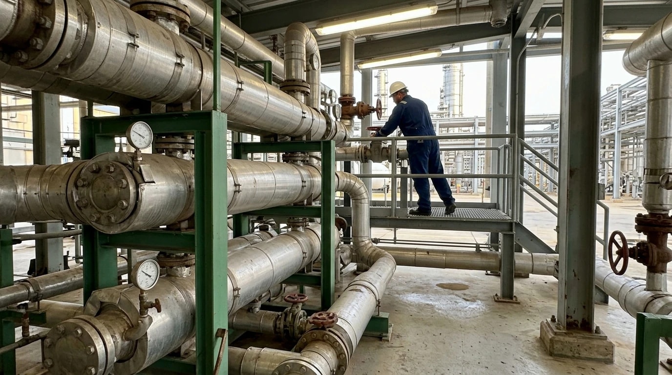
In downstream oil refining and bulk petrochemical manufacturing, process operations involve highly complex preheat trains and distillation systems. These operations process large volumetric flows, meaning even a 1 per cent reduction in thermal energy translates into substantial financial savings.
Applying Pinch Analysis to these facilities typically focuses on optimising crude distillation units (CDUs) and vacuum distillation units (VDUs). Hot products and slipstreams from the fractionating columns are systematically matched with incoming cold crude oil. This preheating process directly reduces the thermal load on the fuel-fired furnace. By redesigning the heat exchanger network using pinch principles, refineries routinely cut fuel gas consumption, resulting in a direct drop in Scope 1 carbon dioxide emissions.
Speciality Chemical and Pharmaceutical Synthesis
Speciality chemical and pharmaceutical facilities operate with different constraints, often relying on batch processing rather than continuous flow. Batch operations introduce temporal challenges, as hot and cold streams may not coexist simultaneously.
To resolve this, engineers apply batch Pinch Analysis, which incorporates thermal energy storage systems. By matching streams across different time intervals and utilising pressurised hot water or thermal oil loops as heat storage media, speciality chemical plants can store excess heat from exothermic reaction steps and release it to heat subsequent batch steps. This method significantly reduces the peak steam demand of the facility, stabilising boiler operations and improving energy efficiency in manufacturing.
Integrating Advanced Waste Heat Recovery Technologies
Beyond standard gas-to-gas or liquid-to-liquid heat exchangers, Pinch Analysis facilitates the integration of advanced waste heat recovery technologies. These technologies include:
- Industrial Heat Pumps: These systems absorb low-grade waste heat from below the pinch, apply mechanical work, and discharge high-grade heat above the pinch where it is needed. Pinch Analysis prevents the common error of installing a heat pump that transfers heat entirely below or entirely above the pinch, which provides zero net utility savings.
- Organic Rankine Cycle (ORC) Systems: When a process has an unavoidable surplus of low-grade heat below the pinch that cannot be integrated, an ORC system can convert this thermal energy into electricity, reducing the plant's grid reliance.
- Boiler Feedwater Preheaters: Utilising low-temperature waste streams to heat boiler makeup water directly reduces the fuel required to generate steam.
Practical Challenges in Heat Exchanger Network Retrofits
Spatial and Piping Constraints in Existing Plants
While implementing Pinch Analysis on greenfield plant designs is straightforward, retrofitting an operational chemical plant presents physical challenges. Existing heat exchangers are fixed in place, and the physical distance between a hot stream and a cold stream can be hundreds of metres.
Running long runs of piping to connect these streams introduces several complications:
- High capital costs for piping, structural supports, and insulation.
- Significant pressure drops, which may require upgrading existing process pumps.
- Thermal losses along the pipe run, which degrade the temperature of the heat source.
To address these spatial limitations, thermal design teams utilise area-wide or zonal Pinch Analysis. This technique divides a large chemical park into distinct physical zones and optimises heat recovery within each zone first, before evaluating high-value thermal connections between zones.
Plant Operability, Control, and Flexibility
Integrating process streams couples different parts of a chemical plant together. In a highly integrated facility, an upset in one reactor system can rapidly propagate through the heat exchanger network, affecting the temperature of a downstream distillation column.
To maintain operational stability, design teams must balance thermodynamic efficiency with process controllability. This is achieved by:
- Installing control valves and bypass lines around critical heat exchangers to allow manual temperature regulation.
- Providing auxiliary utility heat exchangers (such as trim heaters and trim coolers) to maintain precise process temperatures during startup, shutdown, or feedstock variations.
- Using advanced dynamic simulation software to model the control behaviour of the integrated network under transient conditions.
Economic Evaluation and Capital Allocation
Chemical manufacturers evaluate energy efficiency projects against strict financial hurdles. Capital projects typically require a rapid return on investment. A minor pinch retrofit that involves rearranging a few pipelines or adding a single heat exchanger may have a payback period of under 18 months. Conversely, a major network restructuring that requires installing multiple large heat exchangers and extensive piping may require three to five years to break even.
Process engineering consultancies, such as EnerTherm Engineering, provide detailed cost-benefit analyses, plotting the cumulative capital cost against the annual utility savings. This allows senior management to select the optimum design option that aligns with their corporate investment criteria and decarbonisation roadmaps. By translating thermodynamic potential into bankable, low-risk engineering designs, manufacturers can achieve the 15 to 25 per cent reduction in thermal energy necessary to meet both financial targets and compliance mandates.
This article reflects the independent analysis and editorial opinion of EnerTherm Engineering. Product names, trademarks, and brands mentioned belong to their respective owners. EnerTherm Engineering is not affiliated with, endorsed by, or a licensee of any third-party software or product mentioned unless explicitly stated.

Simulation Engineer — EnerTherm Engineering
Rajesh Sekar is a Simulation Engineer at EnerTherm Engineering, specialising in computational fluid dynamics (CFD), finite element analysis (FEA), and thermal process simulation. He holds a degree from Cranfield University and brings extensive experience in simulation-based product development from the automotive, aerospace, and energy sectors.
